 Products Home
顕微鏡用スライド型パワーセンサーヘッド
- Measure Power at the Sample
- Large-Area Sensor to Collect Light from High NA Objectives (up to 1.45)
- Compatible with Dry, Water Immersion, and Oil Immersion Objectives
- Options Available for Low-Power, High-Power, and Multiphoton Applications
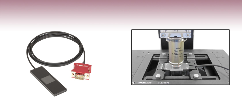
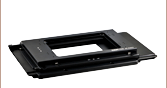
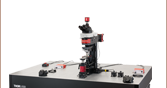
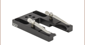
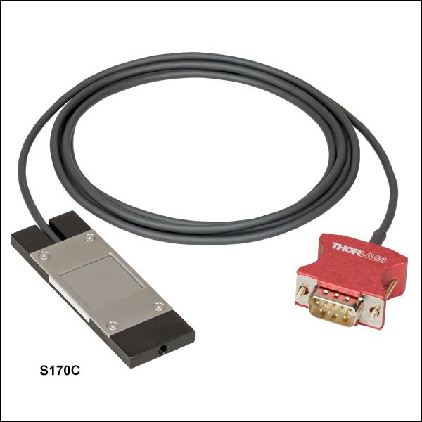
S170C Microscope Slide Power Meter Sensor used with a 1.30 NA Objective and Shown on an MLS203-1 Motorized Scanning Stage Equipped with an MLS203P2 Slide Holder
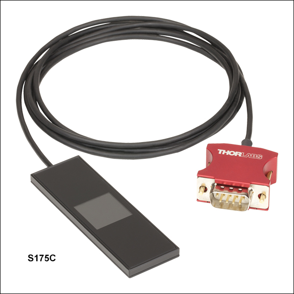
S175C
High-Power Microscope Slide Power Sensor for UV, Visible, and IR


Please Wait

Click to Enlarge
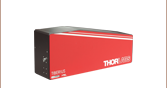
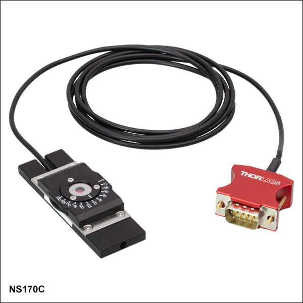
顕微鏡用スライドセンサの筐体の背面には、センサの仕様とビームをセンサ中心に合わせるのに便利なグリッドや十字線が刻印されています。写真はS170Cの背面です。S171Cにも同様の刻印があります。センサS175CとNS170Cの刻印については下の製品紹介の写真でご覧いただけます。

Click for Details
センサ筐体の背面に刻印されたアライメントターゲットを利用してステージの位置を決めれば、センサを反転させたときにビームをセンサの中心に入射させることができます。写真のセンサはS170Cです。
特長
- 標準の正立および倒立顕微鏡に使用可能
- 試料面での光パワーの計測用に設計
- 18 mm x 18 mmの大きな受光面
- 低光パワー測定用フォトダイオードセンサ
- 波長範囲:350 nm~1100 nm (型番170C)または400 nm~1100 nm (型番S171C)
- 光パワー測定範囲:10 nW~150 mW (型番170C)または1 nW~15 mW (型番S171C)
- 高光パワー測定用サーマルセンサ(型番 S175C)
- 波長範囲:300 nm~10.6 μm
- 光パワー測定範囲:100 µW~2 W
- センサの筐体の大きさは一般的な顕微鏡用スライドと同じ76.0 mm x 25.2 mm
- 高NAの対物レンズに対応する新光学設計(「光学設計」タブをご覧ください)
- コネクタに以下の情報を保存
- 当社パワーメーターコンソール使用時(別売り)に有効な自動校正用センサーデータ
- NISTまたはPTBにトレーサブルな校正データ
- 再校正サービスをご提供
用途
- 顕微鏡用照明光の試料面における強度測定
- 蛍光フィルターセットの透過率測定
- 各実験の照明条件に一貫性を確保
顕微鏡用スライドセンサーヘッドを用いると、顕微鏡システム内の試料面における光パワーを測定することができます。センサーヘッドの外形寸法(76.0 mm x 25.2 mm)は標準の顕微鏡用スライドと同じで、センサの受光面は18 mm x 18 mmと大きく、多くの標準的な正立および倒立顕微鏡にお使いいただけます。
低光パワー用の製品にはシリコンフォトダイオードセンサ、高光パワー用の製品にはサーマルセンサが用いられています。フォトダイオードセンサSC170Cは波長範囲350 nm~1100 nmに感度を有し、10 nW~150 mWの光パワーを分解能1 nWで測定できます。フォトダイオードセンサSC171Cは波長範囲400 nm~1100 nmに感度を有し、1 nW~15 mWの光パワーを0.5 pWの分解能で測定できます。これらのセンサは応答時間白色光源などによる広帯域の照明光の測定にも適しています。サーマルセンサS175Cは波長範囲300 nm~10.6 µmに感度を有し、100 µW~2 Wの光パワーを測定できます。このセンサは、仕様の波長範囲で平坦な吸収特性を有するため、LEDや白色光源などによる広帯域な照明光の測定に適しています。

Click to Enlarge
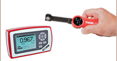
タッチパネル式パワーメーターコンソールPM400(別売り)に接続されたNS170C
使用法について
このセンサは最大NA 1.45までの対物レンズに対する光パワー測定をサポートしており、空気中で水や油の液浸媒体を用いた場合でも使用可能です(詳細は「 光学設計」タブをご覧ください)。右上の写真でご覧いただけるように、センサの背面には気体(< 0.95)、水浸(< 1.30)、油浸(< 1.45)と、各条件で推奨する対物レンズのNAが刻印されています。受光面はガラスカバーで保護されています。ガラスカバーは、圧縮空気、またはアセトンやメタノールで湿らせたレンズ用ティッシュで簡単にクリーニングできます。
上の写真でご覧いただけるように、センサの背面にはアライメント用のグリッドがレーザ刻印されています。これは受光面の位置を表しており、ビームのアライメントや集光の際に役立ちます。標準的な正立顕微鏡に使用する場合は、筐体をその刻印面が顕微鏡の対物レンズに対面する向きにして光路に挿入します。パワーセンサの中心が対物レンズの真下にくるように調整したのち、パワー測定ができるようにスライドを反転させてディテクタの受光面をビームに向けます。倒立顕微鏡に使用する場合は、受光面が対物レンズに向くようにディテクタをスライドホルダにセットし、透過照明用ランプの電源を入れます。ビームの位置を刻印されたターゲットの中心に一致させることで、受光面を光路の中心に一致させることができます。
センサの損傷させないために、ビームが集光されない位置にセンサを配置することをお勧めします。ビームのスポットサイズ内のどの位置においても、最大平均パワー密度(Max Average Power Density、「仕様」タブ参照)を超えないことが重要です。
対応するパワーメーターコンソールとインターフェイス
これらのパワーセンサーヘッドは、パワーメーターコンソールのPM100D、 PM100A、PM400、PM5020、およびセンサとPCなどの外部制御ユニットを接続するためのCシリーズパワー&エネルギーメーターインターフェイスに対応します。下記のコンソールPM100A、PM100D、PM400についての製品紹介で、表示画面や操作スイッチも含めてご覧いただけます。左の写真でご覧いただけるように、センサーヘッドの横に1.5 mのケーブルが付いており、その先には9ピンのオス型Dサブコネクタが付いています。自動校正を行うために、センサ仕様とNISTまたはPTBにトレーサブルな校正データがセンサーコネクタ内の不揮発性メモリに保存されており、当社の対応するパワーメーターコンソールで読み出すことができます。
再校正サービス
当社ではパワーセンサとパワーメーターコンソールの再校正サービスを提供しています。センサとコンソールはセットで再校正されることをお勧めしますが、それぞれを単体で再校正することも可能です。詳細は当社 までお問い合わせください。
| Specifications | |||||
|---|---|---|---|---|---|
| Item # | S170C | S171C | S175C | NS170C | |
| Detector Type | Silicon Photodiode | Thermal Absorber | Second-Order Nonlinear Crystal with Silicon Photodiode | ||
| Wavelength Range | 350 - 1100 nm | 400 - 1100 nm | 300 nm - 10.6 µm | Laser: 780 - 1300 nm SHG: 390 - 650 nm | |
| Optical Power Working Range | 10 nW - 150 mW | 1 nW - 15 mW | 100 µW - 2 W | Laser: 0.5 - 350 mWa SHG: 10 nW - 5 mW | |
| Max Average Power Density | 20 W/cm2 | 10 W/cm2 | 200 W/cm2 | - | |
| Max Pulse Energy Density | - | - | 0.1 J/cm² (1 µs Pulse) 1 J/cm² (1 ms Pulse) | - | |
| Max Peak Power Densityb | - | - | - | 10 TW/cm2 | |
| Linearity | ±0.5% | ±0.5%c | |||
| Resolution | 1 nWd | 0.5 pWe | 10 µWf | 1 nWc,d | |
| Measurement Uncertainty | ±3% (440 - 980 nm)g ±5% (350 - 439 nm)g ±7% (981 - 1100 nm)g | ±3% (440 - 980 nm)g,h ±5% (400 - 439 nm)g,h ±7% (981 - 1100 nm)g,h | ±3% (1064 nm) ±5% (300 nm - 10.6 µm) | ±3% (440 - 650 nm)c,i ±5% (390 - 439 nm)c,i | |
| Responsivity (Click for Plot) |  Raw Data |  Raw Data | - |  Raw Data | |
| Absorption (Click for Plot) | - | - |  Raw Data | - | |
| Typical Application | Light Measurement on the Microscope Objective Plane | GDD Optimization of a Femtosecond Laser at the Focus of a Two-Photon Microscopej | |||
| Neutral Density Filter | Reflective (OD 1.5) | Absorptive (OD 0.4) | N/A | N/A | |
| Cooling | Convection | ||||
| Compatible Consolesk | PM100D, PM100A, PM400, and PM5020 | ||||
| Compatible Interfacesk | PM101, PM101A, PM101R, PM101U, PM103, PM103A, PM103E, PM103U, and PM100USB | PM101, PM101A, PM101R, PM101U, PM102, PM102A, PM102U, and PM100USB | PM101, PM101A, PM101R, PM101U, PM103, PM103A, PM103E, PM103U, and PM100USB | ||
| Response Time | < 1 µs | < 2 s | < 1 µs | ||
| Dimensions | 76.0 mm x 25.2 mm x 5.0 mm (2.99" x 0.99" x 0.20") | 76.0 mm x 25.2 mm x 4.8 mm (2.99" x 0.99" x 0.19") | Base: 76.0 mm x 25.2 mm x 5.0 mm (2.99" x 0.99" x 0.20") Overall: 76.0 mm x 30.0 mm x 11.0 mm (2.99" x 1.18" x 0.43") | ||
| Active Detector Area | 18 mm x 18 mm | ||||
| Input Aperture | 20 mm x 20 mm | 18 mm x 18 mm | Ø4.5 mm | ||
| Working Distance | - | - | - | 0.22 mm | |
| Cable Length | 1.5 m | ||||
| Connector | Sub-D 9 Pin Male | ||||
| Weight | 0.07 kg (0.15 lbs) | 0.05 kg (0.11 lbs) | 0.08 kg (0.18 lbs) | ||
| Post Mounting | Combi Thread 8-32 and M4 x 0.7 | N/A | Combi Thread 8-32 and M4 x 0.7 | ||
Sensor Connector
D-type Male
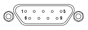
| Pin Connections | ||
|---|---|---|
| Pin | S170C, S171C, and NS170C | S175C |
| 1 | Not Used | |
| 2 | EEPROM Data | |
| 3 | Photodiode Anode Ground | Sensor Ground |
| 4 | Photodiode Cathode | Not Used |
| 5 | Not Used | |
| 6 | EEPROM Ground | |
| 7 | Not Used | Not Used |
| 8 | Not Used | Sensor Signal |
| 9 | Not Used | |
クリーニング方法
顕微鏡用スライド型パワーメータ-センサーヘッドの筐体をクリーニングする際は、湿らせた柔らかいクロスを使用してください。S170CとS171CのNDフィルタは、市販のエアブローでやさしく埃を落としてください。表面のクリーニングには、アセトンやメタノールで湿らせたレンズ用ティッシュで優しく拭き取っていただくことも可能です。S175CとNS170Cのガラス製センサーカバーは、イソプロパノールなどの適切な溶剤でクリーニングすることができます。
校正
センサは過度の光パワーに曝されない限り1年以上は安定しているため、その間は校正データも使用可能です。精度と性能を確保するために定期的な再校正をお勧めします。校正頻度は用途にもよりますが、通常1年程度です。当社では再校正サービスを提供しております。詳細は当社までお問い合わせください。
The sections below describe the various designs of Microscope Slide Power Meter Sensor Heads. Use the following links to jump to a specific section:
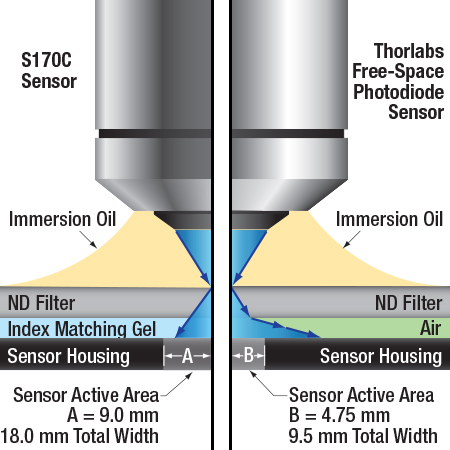
An illustration to show the behavior of light exiting a high NA objective after it enters the S170C microscope power sensor head vs. a typical photodiode sensor. For objectives with NAs greater than 1.0 and a detector without index matching gel in the gap, some of the light will also undergo total internal reflection at the ND filter-air interface, causing additional losses before the light reaches the sensor. (Important Note: Do not place immersion oil or other immersion media directly on the ND filter of any Thorlabs photodiode detectors other than the S170C and S171C sensors, as they were not designed for this application and the oil cannot be cleaned from the filter surface.)
Large Active Area and Index Matching Gel
The S170C, S171C, and S175C microscope slide sensor heads were designed with large-active-area detectors to accommodate high NA objectives. In addition, the S170C and S171C sensors use index matching gel in the gap between the neutral density filter and the sensor to minimize losses due to internal reflections at the air-glass interface. The S175C sensor uses a protective glass cover that features a smaller air gap than the S170C sensor (0.15 mm versus 1.5 mm) to avoid the use of index matching gel, which helps maintain a fast sensor response time.
The schematic to the right illustrates the advantages that a large-area detector like the one used in the S170C sensor provides over typical photodetectors by tracing the path of light from a high NA objective after it enters an S170C microscope slide sensor head and a typical photodiode sensor. The typical photodiode sensor shown in the drawing has an air-filled gap between the ND filtera and the sensor and a Ø9.5 mm active area, similar to our S130 slim photodiode sensors or S120 standard photodiode sensors. When light from a large NA objective reaches the interface between the ND filter and the glass, it refracts away from the center of the sensor. Some of the light misses the edge of the small active area of the photodiode, causing erroneous power measurements.
In the S170C microscope slide sensor head, the gap between the neutral density filter and the sensor active area has been filled with an index matching gel. Compared to the ND-filter-to-air interface in typical sensor heads, the gel minimizes the amount of reflected light at the ND-filter-to-gel interface that would otherwise not reach the sensor and eliminates refraction of light exiting the ND filter, allowing the large-area detector to capture more light from the objective. Please be aware that this design cannot completely compensate for this effect for very high NA oil objectives and at certain wavelengths.
Similar results would be expected from a comparison of the S175C unit with other thermal sensors. The small 0.15 mm air gap between the protective glass plate and the thermal sensor minimizes the light refracted away from the center of the sensor, while the large 18 mm x 18 mm active area catches more of the incoming signal. Additionally, the S175C sensor has a protective class cover plate that allows the appropriate immersion media for the objective to be applied without damaging the sensor. (Note: do not apply immersion media to Thorlabs' other thermal sensors, as it may damage to the sensor head.)
- Do not place immersion media directly on the ND filter of any Thorlabs' photodiode sensors, with the exception of the Microscope Slide Power Sensors that are specifically designed for this application, as the oil cannot be cleaned from the filter surface. The example used here is only intended to demonstrate the advantages of the S170C sensor's optical design.
 Click to Enlarge
An illustration to show the optical design of the NS170C Microscope Slide Peak Power Sensor. An ultrathin β-BBO crystal is used to convert femtosecond NIR laser pulses into their visible second harmonic. Shortpass filters reflect the residual NIR light, allowing only the visible second harmonic light to transmit to the silicon photodiode sensor.
Nonlinear Crystal with Silicon Photodiode Sensor
The NS170C Microscope Slide Peak Power Sensor was designed to measure the relative peak power of two-photon lasers. As shown in the diagram to the right, the sensor features a 30 µm ultrathin β-BBO crystal that converts incident femtosecond NIR pulses (780 – 1300 nm) into their second harmonic (390 – 650 nm). Shortpass filters underneath the β-BBO crystal reject the residual NIR light, allowing only the visible second harmonic light to transmit down to the large area silicon photodiode sensor.
A microscope objective is shown focusing the femtosecond NIR pulses into the β-BBO crystal through a Ø4.5 mm entrance aperture. Because the SHG process requires high peak intensities, the sensor only generates detectable second harmonic light when the ultrathin β-BBO crystal is in the focus of the objective. This means the NS170C sensor is sensitive to the peak power density of the focused femtosecond pulses rather than the average power; therefore, the detected SHG signal can be used as a relative measurement of the lasers' peak intensity. For more details on the generation of second harmonic light using β-BBO crystals, please see the SHG Tutorial tab.
At the top of the NS170C sensor is a standard 170 µm thick cover glass that is sealed to the housing, allowing it to be used with dry, water immersion, and oil immersion objectives. The immersion media can be placed directly on the surface of the cover glass without damaging the sensor. The working distance from the top of the cover glass to the β-BBO crystal is 0.22 mm. Between the cover glass and the β-BBO crystal is an 80 μm air-gap, which is necessary because epoxy or index-matching gel would burn in the focus of the high-intensity femtosecond pulses. While this air-gap causes total internal reflection (TIR) of the highest spatial frequencies when using high NA objectives, the second harmonic process in the β-BBO crystal has a finite spatial frequency acceptance bandwidth, which is exceeded by high NA objectives. Therefore, the highest spatial frequencies rejected by TIR would not appreciably contribute to the SHG process.
The housing of the NS170C sensor shares dimensions with a microscope slide and can fit on standard microscope stages, allowing for measurements of the relative peak power at the focus of a microscope.
For more information on the NS170C sensor, please see the full presentation for our microscope slide peak power sensor for two-photon lasers.
| Posted Comments: | |
Peter Gruber
(posted 2024-05-03 12:18:51.34) Newport is offering a photodiode microscope power sensor up to 600mW instead of the 150mW of the S170C.
https://www.newport.com/f/microscope-slide-photodiode-sensor
Sadly we had bad experience with the thermopile version and we would like to a photodiode alternative.
Is it possible to buy a calibrated version with 600mW of the S170C? dpossin
(posted 2024-05-06 09:18:13.0) Dear Peter,
Thank you for your feedback. At the moment I am not sure if we could extend the S170C to 600mW. I reach out to you in order to discuss your application in more detail. Vanessa Carlos
(posted 2023-04-28 15:02:03.27) Hello,
I would like to know if this power sensor can be completely immersed in water. Or if you have any other photodiode sensors where that is possible. I would need it for measuring power at the sample, on light sheet microscopes, using water immersion objectives, with low NA.
Thank you! dpossin
(posted 2023-05-02 04:33:31.0) Dear Vanessa,
Thank you for your feedback. The S170C is desgined for usage in immersion media. You can see the basic working principle here: https://www.thorlabs.de/newgrouppage9.cfm?objectgroup_id=2191&tabname=optical%20design. I am reaching out to you in order to discuss this further. Jolanda van Iperen
(posted 2023-01-09 16:35:59.607) I am looking for a mini laser intensity power meter that fits under the objectives of a u-Raman microscope (till 100x objective WD 0,17 and can focus with that working distance. It should be able to set laser at 532 nm and 785 nm in order to measure at these wavelength the power of the laser through the objectives, preferable reading the power outside the enclosure, which can be opened a little bit. I came to S170C, but cannot find if this is set to a particular wavelength or gives a spectrum. It would be nice to have both options - also for the LED light of the microscope- , but if not in the first place we prefer the first option to measure intensity of laser 532 and 785 nm. hkarpenko
(posted 2023-01-10 08:45:30.0) Dear Jolanda,
thank you for your feedback. Our sensors won´t be able to show the spectrum of the sensor, but only the power. S175C might be a more suitable sensor if you are measuring both, monochromatic and broadband lightsources. I contact you directly to discuss this in more detail with you. user
(posted 2021-11-09 06:01:57.003) What is the typical ambient-stabilization time between you take it in your hand, place it where you want to measure, and until you can actually measure? In our temp controlled lab, I've seen that this can go up to 10-15 minutes. Is that normal? dpossin
(posted 2021-11-16 06:02:54.0) Dear Carlos,
Thank you for your feedback. The stabilization time depends on the power level you would like to measure. In general thermal power sensors are very sensitive to external heat. Since convection is quite a slow process a settle time of 10 to 15 minutes is nothing to worry about. I am reaching out to you to discuss this further. Holger Knaut
(posted 2021-07-29 10:12:16.853) Hi,
is the S170C compatible with laser light illumination such as a confocal or spinning disk scope?
Thanks soswald
(posted 2021-08-02 03:11:26.0) Dear Holger,
thank you for your feedback.
The S170C can be used to measure laser light as long as the maximum power of 150 mW and the maximum power density of 20 W/cm² are not exceeded.
Please contact your local tech support team with more details on your light source, expected power and power density to discuss your application further. user
(posted 2019-07-03 16:32:40.697) We are looking for a power meter similar to this but maybe one that is a cylinder as we are wanting to characterize an assembly that is illuminated from six points located around the circumference.
Please contact me. MKiess
(posted 2019-07-05 10:20:23.0) This is a response from Michael at Thorlabs. Thank you for your inquiry. I have contacted you directly to discuss further details on custom possibilities and applications for this sensor. g.makey
(posted 2016-05-12 03:50:55.7) Hi,
Can S170C be used in reflective mode microscope while imaging? shallwig
(posted 2016-05-12 05:05:39.0) This is a response from Stefan at Thorlabs. Thank you for your inquiry. I have contacted you directly to discuss how the S170C can be used in your setup. donovan.harris.civ
(posted 2015-12-10 15:28:18.217) Couldn't find compatible meter for the S175C. Using Zeiss compatible collimated LED sources at full power. shallwig
(posted 2015-12-11 06:41:50.0) This is a response from Stefan at Thorlabs. Thank you very much for your inquiry. The S175C sensor is compatible with any of our currently available consoles PM100D, PM100A, PM100USB, PM200, PM320E. I will contact you directly to discuss your application in more detail. cuhrich
(posted 2014-01-21 16:09:02.123) I just noticed that my comment is the same as one posted here. We need this device built with a stronger ND filter as we will have powers closer to 1W down on the sample. Seems like a reasonable option to offer a high power version. tschalk
(posted 2014-01-23 04:56:30.0) This is a response from Thomas at Thorlabs. Thank you very much for your inquiry. At the moment we are not able to equip the sensor with a stronger ND-filter because these does not meet our specifications. 1W is far away from the current specification and we hope to increase the maximum power level up to 300mW in the future. I will contact you directly to discuss your application. flickingerd
(posted 2013-11-01 08:24:21.293) A model with Pmax 500 mW would be nice (powers like this are normal for narrow bandwidth 2P microscopy). tschalk
(posted 2013-11-06 03:19:31.0) This is a response from Thomas at Thorlabs. Thank you very much for your inquiry. At the moment we can not provide a sensor with a higher power range because of the optical filter that is used. I will contact you directly to discuss your application and find a suitable solution. cbrideau
(posted 2013-08-01 16:38:44.763) Looking good, but how do you deal with the NA narrowing imposed by the Si detector's high index of refraction (>3)? |

 ズーム
ズーム| Item #a | S170C | S171C |
|---|---|---|
| Wavelength Range | 350 - 1100 nm | 400 - 1100 nm |
| Optical Power Working Range | 10 nW - 150 mW | 1 nW - 15 mW |
| Max Average Power Density | 20 W/cm2 | 10 W/cm2 |
| Resolution | 1 nWb | 0.5 pWc |

Click to Enlarge
S170Cは、筐体側面にあるM4タップ穴を使用してポストに取り付けることができます。
- 18 mm x 18 mmの大きな受光面
- 高NA対物レンズからの光の測定や光路上の任意の位置での光測定に便利
- 当社では再校正サービスを提供しております。詳細は当社までお問い合わせください。
- M4タップ穴を利用してポストに取付け可能
顕微鏡用のスライド型パワーメータフォトダイオードセンサーヘッドS170Cおよび S171Cは、標準的な正立および倒立顕微鏡のスライドホルダに適合するように設計されており、これらを用いて試料面における光パワーを測定することができます。受光面は密封された筐体に納められており、その前面には光学濃度(OD)1.5 (型番S170C)または0.4 (型番S171C)のNDフィルタが付いています。NDフィルタ上の20 mm x 20 mmのくぼみには、カバースリップや液浸材を入れられます。液浸材(水、グリセロール、油など)はこの中(NDフィルタの上)に直接つけることができます。または、クリーニングを容易にするために、最初にカバースリップを挿入することもできます。S170CとS171CのNDフィルタとセンサの間の隙間には屈折率マッチングジェルが入っており、空気とガラスの境界面での内部反射による損失は最小限に抑えられています。これらの物理的特性については、「光学設計」タブにその概要が記載されています。
このフォトダイオードセンサS170Cは、1 µsの高速応答時間、10 nWの最小検出光パワー、1 nWの分解能といった特性を有し、低パワーの照明の光パワーを高分解能で測定するのに適しています。また当社では、最小検出光パワーが1 nW、分解能が0.5 pWのセンサS171Cもご用意しております。水浸対物レンズを用いるときは、水により特に近赤外域において透過光の一部が吸収されます。そのため、水が無いときの光パワーの読取値は、水が有るときの読取値よりも高くなります。
スライドの背面にはセンサの仕様とビームアライメント用のグリッドが刻印されています。センサを対物レンズに向けるだけでパワーの測定を行うことができます。倒立顕微鏡では、透過照明用ランプをグリッドの中心に置くことで、センサがビームの中心にあることを確認できます。
センサS170CとS171Cは、定期的な再校正をお勧めしています。校正頻度は用途にもよりますが、通常1年程度です。当社では再校正サービスを提供しております。詳細は当社までお問い合わせください。

 ズーム
ズーム| Key Specificationsa | |
|---|---|
| Wavelength Range | 300 nm - 10.6 µm |
| Optical Power Working Range | 100 µW - 2 W |
| Max Average Power Density | 200 W/cm2 |
| Resolutionb | 10 µW |

Click to Enlarge
S175Cの筐体の背面には、センサの仕様とビームをセンサの中央に入射させるためのターゲットが刻印されています。
- 高パワー用サーマルセンサ:波長範囲300 nm~10.6 µm
- 100 µW~2 Wの光パワー測定用
- 18 mm x 18 mmの大きな検出部
- 高NA対物レンズからの光や光路に沿ったあらゆる位置の光測定に便利
- 当社では再校正サービスを提供しております。詳細は当社までお問い合わせください。
顕微鏡用スライド型光パワーメーターヘッドS175Cは、標準的な正立および倒立顕微鏡のスライドホルダに適合するように設計されており、試料面での光パワーを測定することができます。18 mm x 18 mmの大きな検出部を持つセンサはガラスプレートで保護されており、センサ部にも液浸材を塗布することができます。2秒未満の応答時間、100 µW~2 Wの光パワー範囲、そして10 µWの分解能により、この光パワーセンサはLEDや白色照明など高出力の広帯域光源の測定に適しています。水浸対物レンズを用いるときは、水により特に近赤外域において透過光の一部が吸収されます。そのため、水が無いときの光パワーの読取値は、水が有るときの読取値よりも高くなります。
スライドの背面には右の写真のようにセンサの仕様とビームアライメント時のターゲットマークが刻印されています。センサ面を対物レンズに向けるだけでパワーの測定を行うことができます。倒立顕微鏡では、センサの中央に確実にビームが来るように透過照明でグリッドの中央を照らすことができます。
なお、この製品はサーマルセンサなので、通気穴や周囲温度の大きな変化に敏感であることをご配慮ください。センサが一旦周囲温度になってから測定をしてください。
センサS175Cは定期的な再校正をお勧めしています。校正頻度は用途にもよりますが、通常1年程度です。当社では再校正サービスを提供しております。詳細については当社までお問い合わせください。

 ズーム
ズーム| Key Specificationsa | |
|---|---|
| Laser Wavelength Range | 780 - 1300 nm |
| SHG Wavelength Range | 390 - 650 nm |
| Laser Optical Power Working Rangeb | 0.5 - 350 mW |
| SHG Optical Power Working Range | 10 nW - 5 mW |
| Max Peak Power Densityc | 10 TW/cm2 |
| Resolutiond | 1 nW |
 Click to Enlarge
The back of the NS170C housing is engraved with the sensor specifications and a target for centering the beam on the sensor.
- Utilizes a Second-Order Nonlinear Crystal to Measure the Relative Peak Power of Two-Photon Lasers
- Input Laser Wavelength Range: 780 - 1300 nm
- Second-Harmonic Wavelength Range: 390 - 650 nm
- Ideal for Optimizing Laser Conditions at the Sample Plane of a Microscope
- Compatible with Dry, Water Immersion, and Oil Immersion Objectives
- Yearly Recalibration Recommended (For More Information, Contact Tech Support)
- See the Full Web Presentation for More Information
The NS170C sensor is designed to measure the relative peak power of two-photon lasers by utilizing a second-order nonlinear β-BBO crystal to convert incident ultrafast NIR pulses into their visible second harmonic. Shortpass filters underneath the β-BBO crystal reject the residual NIR light, allowing only the second harmonic light to transmit down to a large area silicon photodiode sensor (see Optical Design tab for details). Because the efficiency of second harmonic generation (SHG) is proportional to the peak power density, or peak intensity, of the NIR femtosecond pulses, the magnitude of the detected second harmonic light provides a relative measurement of the peak power of the laser.
The NS170C sensor can be used with femtosecond lasers with center wavelengths from 780 nm to 1300 nm and average powers from 0.5 mW to 350 mW; however, because the photodiode measures the converted SHG signal, it is not sensitive to the average power of the input laser alone, but rather the peak power density of the laser pulses. The damage threshold for the peak power density is 10 TW/cm2 at 80 MHz repetition rate and for microscope objectives with NA > 0.5; the damage threshold will be lower for NA < 0.5. The photodiode sensor can detect SHG light with wavelengths from 390 nm to 650 nm at optical powers from 10 nW to 5 mW with a resolution of 1 nW. Please see the Specs tab for more information.
The NS170C sensor has the same footprint (76.0 mm x 25.2 mm) as a standard microscope slide and is compatible with microscope slide holders of standard upright and inverted microscopes. This design enables the sensor to measure the relative peak power at the focus of the microscope, making it ideal for laser pulse optimization for multiphoton imaging. The sensor is also post-mountable via an 8-32 (M4 x 0.7) tapped hole, allowing for the relative peak power to be measured in an optical set-up of standard optomechanical components.
 Click to Enlarge
The NS170C sensor features a knurled phase adjustment wheel to tune the rotational orientation of the β-BBO crystal.
As shown in the photo to the left, the housing of the NS170C sensor features a knurled adjustment wheel to tune the angle between the light's polarization orientation and the β-BBO crystal's optical axis. At the entrance of the sensor is a 170 µm thick cover glass sealed to the sensor housing, allowing the sensor to be used with dry, water immersion, and oil immersion objectives. The working distance from the top of the cover glass to the β-BBO crystal is 0.22 mm. The back of the sensor housing features a laser-engraved alignment crosshair that marks the active sensor area to aid in aligning and focusing the beam.
Thorlabs recommends yearly recalibration of the NS170C sensor. Recalibration of a single-channel power and/or energy meter console or interface is included with the recalibration of a sensor at no additional cost. For more information on recalibrating the NS170C sensor, please contact Tech Support.
For more information on the NS170C power sensor, please see the full presentation for our microscope slide peak power sensor for two-photon lasers.
こちらでは当社で人気の高いパワーメーターコンソールをご紹介しています。デジタルパワーメーターコンソールPM100DはLEDバックライトのスクリーンを採用しており、1 GBの外付けSDメモリカードが付属しています。タッチパネル式パワーメーターコンソールPM400は、PM100Dと同じ機能を有するうえに、パワー測定値を保存するための4 GBの内蔵メモリ、温度・湿度センサ用の外部入力端子、プログラム可能なGPIOポート、マルチタッチジェスチャーでユニットを操作できる静電容量方式タッチパネルディルプレイなども備えています。またPM400では、光パワー測定データ、温度記録、スペクトル補正曲線、減衰補正データなどを保存し、それらをコンソールと外部機器間で転送してさらに分析することができます。これらの機能は、試料面における光パワーを継続的に観察し、その一貫性をモニタするのに大変便利です。詳細は表内の型番をクリックして各パワーメーターコンソールの製品紹介ページをご覧ください。
また、センサS170C、S171C、S175CおよびNS170Cは、コンソールPM5020および旧製品のPM200とPM320Eにも対応します。これら3種類の全センサは、センサとPCなどの外部制御ユニットを接続するために、PM100シリーズやPM100USBといったインターフェイスも使用可能です。またパワーセンサS170C、S171CおよびNS170CはPM103 シリーズのインターフェイス、S175CはPM102 シリーズのインターフェイスにも対応します。
| Item # | PM100A | PM100D | PM400 |
|---|---|---|---|
| Console Image (Click the Image to Enlarge) |  |  | 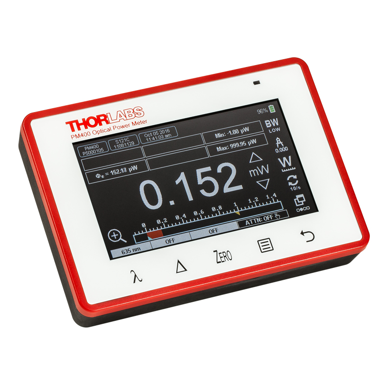 |
| Display | Mechanical Needle and LCD Display with Digital Readout | 320 x 240 Pixel Backlit Graphical LCD Display | Projected Capacitive Touchscreen with Color Display |
| Output | Analog Needle or Digital Numeric Readout | Numerical, Bar Graph, Statistics, Simulated Analog Needle | Numerical with Bar Graph, Trend Graph (Power or Energy and Temperature), Statistics, Simulated Analog Needle |
| Calibration Functions | Wavelength Correctiona | Wavelength Correctiona | Wavelength Correctiona; Also Accepts User-Input Source Spectra and Attenuation Correction Data |
| Data Storage and Transfer | USB 2.0 Interface | 1 GB External SD Memory Card, USB 2.0 Interface | 4 GB Internal Memory Mini B USB 2.0 Interface |
| Dimensions | 7.24" x 4.29" x 1.61" (184 mm x 109 mm x 41 mm) | 7.09" x 4.13" x 1.50" (180 mm x 105 mm x 38 mm) | 5.35" x 3.78" x 1.16" (136.0 mm x 96.0 mm x 29.5 mm) |
| Display Dimensions | 1.9" x 0.5" (48.2 mm x 13.2 mm) Digital Display and 3.54" x 1.65" (90.0 mm x 42.0 mm) Analog Display | 3.17" x 2.36" (81.4 mm x 61.0 mm) | 3.7" x 2.1" (95 mm x 54 mm) |
※パワーセンサ校正について - 当社のパワーセンサ校正は自動で行われており、測定と同時にセンサ内のメモリにある補正データを書き換えます(出力されるデータは校正前の感度と校正後の感度になります)。また、センサ面(NDフィルタ)が汚れ等で正常に感度測定ができないと判断された場合には、フィルタ交換(無償)してから校正される場合がございますので、ご了承ください。この場合は校正前の感度は測定できません。測定と校正を別々に実施する場合には、事前のご連絡が必要です。また、校正のみの場合とは金額および期間が異なりますのでご注意ください。
| Calibration Service Item # | Compatible Microscope Slide Power Sensor |
|---|---|
| CAL-PD | S170C and S171C |
| CAL-THPY | S175C |
Thorlabs offers recalibration services for our microsope slide power sensors. To ensure accurate measurements, we recommend recalibrating the sensors annually. Recalibration of a single-channel power and/or energy meter console or interface is included with the recalibration of a sensor at no additional cost. If you wish to calibrate one or more sensors with a dual-channel console, each sensor and console calibration service will need to be purchased individually.
Refer to the table to the right for the appropriate calibration service Item # that corresponds to your microscope slide power sensor.
Requesting a Calibration
Thorlabs provides two options for requesting a calibration:
- Complete the Returns Material Authorization (RMA) form. When completing the RMA form, please enter your name, contact information, the Part #, and the Serial # of the item being returned for calibration; in the Reason for Return field, select "I would like an item to be calibrated." All other fields are optional. Once the form has been submitted, a member of our RMA team will reach out to provide an RMA Number, return instructions, and to verify billing and payment information.
- Select the appropriate sensor calibration Item # below, enter the Part # and Serial # of the sensor that requires recalibration, and then Add to Cart. If you would like a console calibrated with your sensor, repeat this process for Item # CAL-PM1 or CAL-PM2 below, entering the console Item # and Serial #. A member of our RMA team will reach out to coordinate the return of the item(s) for calibration. Note that each console calibration Item # represents the cost of calibrating a console alone; if requesting a single-channel console calibration with a sensor calibration, the appropriate discount will be applied when your request is processed. Should you have other items in your cart, note that the calibration request will be split off from your order for RMA processing.
Please Note: To ensure your item being returned for calibration is routed appropriately once it arrives at our facility, please do not ship it prior to being provided an RMA Number and return instructions by a member of our team.
※パワーセンサ校正について - 当社のパワーセンサ校正は自動で行われており、測定と同時にセンサ内のメモリにある補正データを書き換えます(出力されるデータは校正前の感度と校正後の感度になります)。また、センサ面(NDフィルタ)が汚れ等で正常に感度測定ができないと判断された場合には、フィルタ交換(無償)してから校正される場合がございますので、ご了承ください。この場合は校正前の感度は測定できません。測定と校正を別々に実施する場合には、事前のご連絡が必要です。また、校正のみの場合とは金額および期間が異なりますのでご注意ください。
| Calibration Service Item # | Compatible Consoles & Interfaces |
|---|---|
| Single-Channel | |
| CAL-PM1 | PM100D, PM100A, PM400, PM100USB, PM101 Series, PM102 Series, PM103 Series |
| Dual-Channel | |
| CAL-PM2 | PM5020, Previous-Generation PM320E |
These recalibration services are for the power and/or energy meter electronics of our consoles and interfaces. To ensure accurate measurements, we recommend recalibrating annually. Recalibration of a single-channel console or interface is included with these sensor recalibration services at no additional cost. If you wish to calibrate one or more sensors with a dual-channel console, each sensor and console calibration service will need to be purchased individually. For more details on these recalibration services, please click the Documents (![]() ) icons below.
) icons below.
The table to the upper right lists the power and/or energy meter consoles and interfaces that can be calibrated using the CAL-PM1 and CAL-PM2 recalibration services.
Requesting a Calibration
Thorlabs provides two options for requesting a calibration:
- Complete the Returns Material Authorization (RMA) form. When completing the RMA form, please enter your name, contact information, the Part #, and the Serial # of each item being returned for calibration; in the Reason for Return field, select "I would like an item to be calibrated." All other fields are optional. Once the form has been submitted, a member of our RMA team will reach out to provide an RMA Number, return instructions, and to verify billing and payment information.
- Select the appropriate Item # below, enter the Part # and Serial # of the item that requires recalibration, and then Add to Cart. If you would like to calibrate one or more sensors with your console, repeat this process for the appropriate sensor recalibration service above, entering the console Item # and Serial #. A member of our RMA team will reach out to coordinate return of the item(s) for calibration. Note that each console calibration Item # represents the cost of calibrating a console alone; if requesting a single-channel console calibration with a sensor calibration, the appropriate discount will be applied when your request is processed. Should you have other items in your cart, note that the calibration request will be split off from your order for RMA processing.
Please Note: To ensure your item being returned for calibration is routed appropriately once it arrives at our facility, please do not ship it prior to being provided an RMA Number and return instructions by a member of our team.