 Products Home
ジンバル式ミラーマウント

- Pure Rotational Motion About Center of Mirror Face
- Minimal Crosstalk Between Axes
- Compatible with Ø1/2" Posts or 30 mm Cage Systems
GMB1
Full Gimbal Mount for Ø1" Optics
(Post Not Included)
GM100
Gimbal Mount for Ø1" Optics
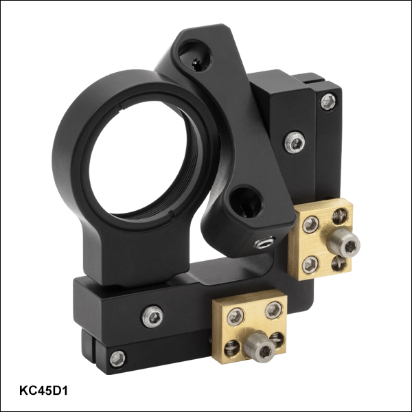
KC45D1
Gimbal Mount for Ø1" Optics
30 mm Cage Compatible
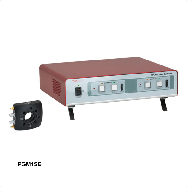
PGM1SE
Piezoelectric Gimbal Mount (Includes Controller)


Please Wait

Click to Enlarge
標準的なキネマティックマウントとジンバル式ミラーマウントとの比較
特長
- 硬化スチール製インサートを用いた手動ジンバル式ミラーマウント
- 並進移動を伴わない、ミラー中心周りのジンバル回転
- 耐久性と安定性に優れた設計
- 黒色アルマイト加工
当社では、並進移動を伴わずに回転を行なうジンバル式ミラーマウントをラインナップしています。いずれの製品も光学素子の前面の中心に対して回転します。これらのマウントは、ビームを操作したときの角度や位置のクロストークを排除するように設計されています。
ジンバル式ミラーマウントGMB1/Mはどちらの軸も360°の粗調整と±15°の微調整が可能です。Ø25 mm~Ø25.4 mm(Ø1インチ)光学素子用ジンバル式マウントGM100/MおよびØ50 mm~Ø50.8 mm光学素子用ジンバル式マウントGM200/Mは、アジャスターノブが2つともマウント上部に付いているため、スペースが限られているセットアップ内で操作するときに便利です。ジンバル式ミラーマウントKC45D1は30 mmケージシステムに組み込むことができます。
PGM1SE/Mは、2つの回転軸をもつ電動式のØ25 mm~Ø25.4 mm(Ø1インチ)光学素子用ジンバル式マウントです。 開ループモード時の各軸の角度範囲は30 mrad、分解能は0.05 µradです。 内蔵の歪みゲージフィードバックにより閉ループモード動作も可能です。角度範囲は20 mrad、分解能は0.14 µradとなります。マウントはKinesis®および APT™モーションコントロールソフトウェアをサポートし、工場で校正済みのコントローラとともに発送されます。
マウントの摩耗しやすいすべての重要な部分は、硬化スチール製のインサートにより強化されています。
| Posted Comments: | |
Dan Ray
(posted 2023-06-26 13:44:44.807) Hello, is it possible to know the smallest angular displacement attainable on the GM100, and how does it compare to a standard KM100 ? Thanks ! jdelia
(posted 2023-06-26 01:02:36.0) Thank you for contacting Thorlabs. We do not specify a smallest angular displacement for either mount as that is dependent on the dexterity of the end user. However, if you are interested in angular resolution, that would be around 0.37 degree/rev for the KM100. We do not have anything more specific than that since the KM100 knob does not have graduations. Regarding the GM100, there are 50 graduations per revolution, and we do not have a singular resolution specification since the motion is not perfectly linear. We do have angular displacement data available under the "Overview" section of the product family page, as well as at the following link: https://www.thorlabs.com/images/TabImages/Gimbal_Mount_Angular_Displacement.xlsx. Simonas Indrišiūnas
(posted 2022-03-23 03:58:40.717) Hello,
is it possible to use Thorlabs motorized actuators with 1/4"-80 mounting thread for the GM100 mirror mount? jdelia
(posted 2022-03-24 08:21:07.0) Thank you for contacting Thorlabs. Unfortunately, we do not offer any motorized actuators that are compatible with the GM100 mount, as the mount uses 3/16"-100 threaded adjuster screws. The only gimbal mount we offer with motorized capability is the PGM1SE. I have contacted you directly to further discuss your application. user
(posted 2021-12-21 13:35:01.64) The point of rotation is stated as being the center of the optic's surface. Surely this cannot be true for any optic thickess or position within the mount. There can only be one point in space within the mount for which the movement is purely rotational. Where is that point? jgreschler
(posted 2021-12-27 12:06:34.0) Thank you for reaching out to Thorlabs. The gimbal surface is defined by the inside lip of the mounting bore. This is also the surface that the mirror surface would rest on making the point of rotation the front center of the mirror surface. Daniel Repp
(posted 2021-08-02 07:17:36.35) Hello!
I was wondering if you also have a Gimbal mount for 2 inch optics and how expensive this would be.
Best Regards
Daniel YLohia
(posted 2021-08-05 01:22:50.0) Hello Daniel, thank you for contacting Thorlabs. Unfortunately, we don't have a 2" option for the GMB1. That being said, we do offer the GM200, which is a gimbal mount for 2" optics. user
(posted 2021-04-21 15:49:45.237) Dear Thorlabs,
Are you selling a motorized version of the GMB1/M Gimbal mount? And if you don't, do you know if the control knobs can be replace by a stepper motor? YLohia
(posted 2021-04-29 01:43:47.0) Hello, we are currently selling the PGM1SE/M Piezoelectric Gimbal Mirror Mount. Unfortunately, the GMB1/M cannot be motorized. Ludo
(posted 2021-03-16 07:49:22.33) Your GMB1/M is great but I actually rarely use the micrometers for fine adjustment, the manual coarse adjustments in pitch and yaw are well damped and with a bit of practice have suffice for most of my needs. So I am writing you to suggest that you offer a version of this gimbal without the fine adjusters, and of course at a lower cost than the GMB1/M. YLohia
(posted 2021-03-16 12:12:52.0) Hello, thank you for your feedback. We currently don't offer these, but we will consider adding such items to our catalog in the future. nentezarian
(posted 2018-09-18 09:32:14.907) Are the GM100 micrometer adjusters lockable? YLohia
(posted 2018-09-18 03:53:44.0) Hello, thank you for contacting Thorlabs. Unfortunately, the adjusters on the GM100 are not lockable. gesuele
(posted 2017-01-22 14:23:18.817) Is it possible to use gimbal mount replacing its manual actuators with two motorized ones? In order to use it as alternative to galvomirror?
If yes what motorized actuator do you suggest? user
(posted 2016-05-04 21:55:04.29) Although the GM100/M is presented as metric, the M4 tapped holes are 0.5in and 1in apart, and not 25mm!
Can you make the M4 tapped holes 25mm apart? Thanks besembeson
(posted 2016-05-05 11:37:14.0) Response from Bweh at Thorlabs USA: We will review this drawing. You can contact me at techsupport@thorlabs.com for updates. max1034
(posted 2016-04-08 04:21:51.93) when i control the pitch and yaw to get light alignment, if it doesn't working, what should i do? besembeson
(posted 2016-04-11 11:53:22.0) Response from Bweh at Thorlabs USA: I will contact you to further discuss your application. user
(posted 2013-07-25 15:47:36.893) You really need to make a GMB1S serie for square optics, built with extreme low tolerance on the horizontal alignment (fixed roll at 0°).
Everytime you sell a $70 grating, Newport sells a $300 gimball mount, just because your KGM serie is so not convincing: they lack the roll axis and can't even be placed on the rotation axes of the GMB1, or any KMxxx. cdaly
(posted 2013-07-25 18:45:00.0) Response from Chris at Thorlabs: Thank you for your feedback. I have begun an internal discussion with our engineers regarding your request. We are currently in the final stages of designing a gimbal prism mount and I believe we may be able, with some redesign, offer this as a grating solution as well. jeff.bull
(posted 2013-03-08 18:03:55.66) What is the angle per revolution for the GM100/M? The pdf cad drawing says 0.035deg/rev, while for the GM100 it says 0.35deg/rev. On my GM100/M I am seeing about 75% of the 0.35 value, so about 0.26deg/rev.
What is it supposed to be and how much variation can I expect to see from the spec across the adjustment range?
thanks! jlow
(posted 2013-03-14 14:41:00.0) Response from Jeremy at Thorlabs: It seems that we made a mistake on the drawing for this. Please note that the angular displacement per revolution of the knob is not linear. I will e-mail you the angular displacement data for a GM100 we have on hand. Thank you for letting us know about this. We will be updating the web drawings shortly. hha07
(posted 2013-02-18 08:16:20.493) How does the Gimbal mount compare to the Polaris mount with respect to long term stability and angular positioning performance? cdaly
(posted 2013-02-27 15:50:00.0) Response from Chris at Thorlabs: Unfortunately we do not have any data directly comparing the gimbal points to the Polaris line. My sense is that the Polaris mounts are more thermally stable as this is one of the main reasons behind the design. i will contact you directly to discuss this further. tcohen
(posted 2012-04-19 15:41:00.0) Response from Tim at Thorlabs: Thank you for your feedback. The point of rotation for both axes is located at the center of the mounted optic’s surface. This does not have translational movement, but pitch and yaw. I will contact you with more information. scottrowe
(posted 2012-04-18 23:14:43.0) Where is the gimbal axes located within this mount? Obviously the center of the aperture for x and y, but z is not obvious. jjurado
(posted 2011-07-14 13:17:00.0) Response from Javier at Thorlabs to avle: The purpose of the two setscrews located at the top and bottom of the GM100 is not for locking the rotation of the mount. They are used to secure the back plate of the mount in place while the front plate rotates through the two gimbal axes. avle
(posted 2011-07-13 17:47:01.0) are the two set screws seen in the GM100 used for locking position of the mount? |
光学素子用ジンバル式ミラーマウント")
 ズーム
ズーム- ジンバル式設計
- 光学素子の最大許容厚さ: 6.4 mm
- Ø25 mm~Ø25.4 mm(Ø1インチ)の光学素子を取付け
- 1回転あたり1°の角度変位で±15°の範囲の微調整
- 固定可能な設計
- クロストークのない優れたキネマティック性能
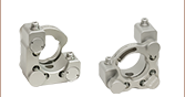
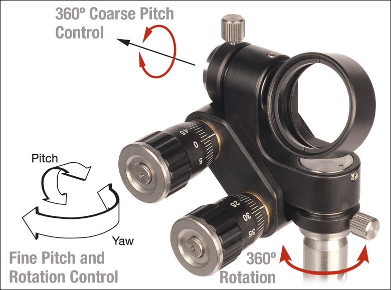
ジンバル式ミラーマウントGMB1/Mは、厚さ6.4 mm までのØ25 mm~Ø25.4 mm光学素子用に設計されていて、ビームを誘導する際にクロストークを除去するために真のジンバル動作を行ないます。両軸の回転中心は、取付けられた光学素子の面中心に位置します。GMB1/Mでは、ロック用つまみネジと微調整アジャスタにより、粗調整と微調整の両方を行なうことができます。粗調整では、360°の自由度で手動角度調整が可能です。微調整では、1回転あたり1°の角度変位が生じる調整ノブの回転により、±15°の範囲で調整が可能です。同様にポストに最も近いつまみネジや止めネジ(セットスクリュ)を使ってヨー調整も行えます。必要なあおり調整(ピッチ&ヨー)を行った後につまみネジと止めネジを締め付けることで、マウント全体の位置固定が簡単に行えます。非常に小型なので、狭い光路にもお使いいただけます。
またはØ50 mm~Ø50.8mm(Ø2インチ)")
 ズーム
ズーム
- 真のジンバル式設計
- 光学素子の最大許容厚さ: 16 mm
- GM100/M - Ø25 mm~Ø25.4 mm(Ø1インチ)の光学素子をマウント
- GM200/M - Ø50 mm~Ø50.8 mm(Ø2インチ)の光学素子をマウント
- 内部共振器用に設計
- 角度範囲:±2.5°(GM100/M)または±2.0°(GM200/M)
- 目盛付き調整ノブ(100 TPIアジャスタ)
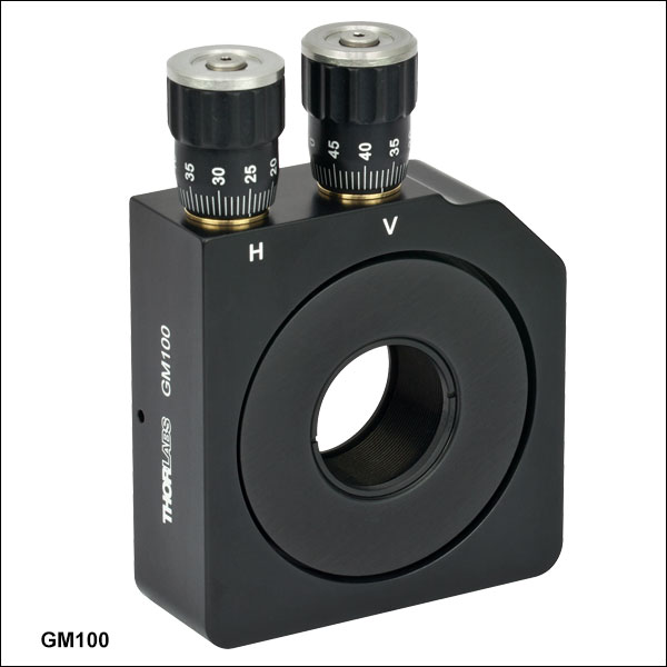
当社のジンバル式ミラーマウントは、内部共振器向けに設計されていて、光学面を回転軸上に配置する真のジンバル式設計が採用されています。この設計により、角度や位置のクロストークがない純粋な回転動作が可能になります。
2 個の調整ノブ(1回転あたり50目盛付き)はマウントの上面に付いており、マウントが光学系に組み込まれた後でも簡単に操作することができます。このノブは、優れた角度調整性能を備えています。GM100/MはØ25 mm~Ø25.4 mm(Ø1インチ)、GM200/MはØ50 mm~Ø50.8 mm(Ø2インチ)の光学素子を保持できるように設計されています。これらのマウントにはそれぞれSM1シリーズのネジ切り加工とSM2シリーズのネジ切り加工が施されており、当社のレンズチューブやアクセサリが取付け可能です。また、光学素子固定用の固定リングが付属します。
注:内部駆動機構により、このマウントの調整ノブによる動きは完全な直線運動ではありません。個別の測定結果についてはこちらをご参照ください。
光学素子用ジンバル式ミラーマウント、30 mmケージシステム用")
 ズーム
ズーム
Click to Enlarge
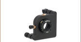
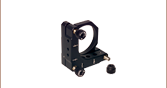
ジンバル式マウントとスイベル式カプラを組み合わせると、ケージシステム内で45°以外の入射角が可能となります。

Click to Enlarge
30 mmケージシステム内のジンバル式マウントKC45D1
- ジンバル式の設計
- 光学素子の最大厚さ: 6 mm
- Ø25.0 mm~Ø25.4 mm(Ø1インチ)光学素子を取付け
- 当社の30 mmケージシステムに対応
- 光学素子ホルダを360º 回転
- 光学素子ホルダのサドル上で±30º回転
ジンバル式ミラーマウントKC45D1は、ジンバル式移動でØ25.0 mm~Ø25.4 mm(Ø1インチ)光学素子を30 mmケージアセンブリの中心ポイントで回転させるように設計されています。光学ホルダは360º自由に回転します。角度方向を大まかに設定した後、つまみネジ型六角レンチHKTS-5/64などの5/64インチ六角レンチまたはボール(六角)ドライバを使用して、微調整機構(1回転あたり13 mrad/revの調整が可能な2個の100 TPIアジャスタ)で精密アライメントが可能です。中間にあるサドルを回転させることによって、第2の回転自由度として角度をある程度調整できます。このサドルは光学ホルダとケージアセンブリを接続して±30º自由に回転します。光学素子はSM1タップ穴の後ろ端に保持され、付属の固定リングSM1RRで固定できます。
光学素子用ピエゾアジャスタ付きジンバル式ミラーマウント、コントローラ付き")
 ズーム
ズーム| Key Specifications | ||
|---|---|---|
| Piezo Specifications | ||
| Resonant Frequency (7.0 g Load) | 360 Hz ± 15% | |
| Piezo Angular Range | 30 mrad (Open Loop) 20 mrad (Closed Loop) | |
| Angular Resolution | 0.05 µrad (Open Loop) 0.14 µrad (Closed Loop)a | |
| Piezo Control Voltage | -25 to 150 V | |
| Piezo Drive Connectors | Male SMCb | |
| Strain Gauge Connectors | Male 7-Pin LEMOb | |
| Mechanical Specifications | ||
| Optic Size | Ø1.00" (Ø25.4 mm) | |
| Optic Thickness | 2 mm (0.08") Min 7.5 mm (0.30") Max | |
| Post Mounting Features | 8-32 (M4) Mounting Taps | |
| Cage System Compatibility | Four 4-40 Taps for 30 mm Cage Rods | |
- 閉ループ動作用の歪みゲージフィードバックセンサ
- 付属のコントローラと組み合わせて使用
- 取り付けた光学素子の中心が移動しないジンバル回転
- 広い角度範囲:30 mrad(開ループ時)または20 mrad(閉ループ時)
- Ø25 mm~Ø25.4 mm(Ø1インチ)光学素子に対応するSM1ネジ付き内孔
- 4隅の貫通穴で30 mmケージシステムへの組込みが可能
ピエゾアジャスタ付きジンバル式ミラーマウントPGM1SE/Mは、取り付けられた光学素子を、その中心位置を動かさずに2つのジンバル軸周りに回転させます。開ループモードでは、ピエゾにより軸ごとに30 mradの広い角度範囲を0.05 µradの分解能で走査できます(閉ループモードでの走査角度範囲は20 mrad 、分解能は0.14 µrad)。
光学素子用のSM1ネジ付き内孔には、Ø25 mm~Ø25.4 mm(Ø1インチ)の光学素子を付属のSM1固定リングで固定します。厚さ2 mm~7.5 mmの光学素子を保持できますが、それらの光学素子はマウントの背面から取り付けるため、厚さに関わらずその表面がジンバル軸と一致します。ネジにSM1レンズチューブを取り付けるとジンバル素子に過度なトルクがかかるためお勧めいたしません。
マウント上にはM4タップ穴が6つあり、Ø12 mm~Ø12.7 mm(Ø1/2インチ)ポストに取付け可能です。また、マウントの両側の内孔周囲には30 mmケージシステムに取付けられる#4-40タップ穴が4つあります。
ステージにはピエゾコントローラが付属しますが、これらはそれぞれのステージ用に工場で校正され、-25~+150 VDCの電圧を供給します。ピエゾの制御はペアになっているコントローラを用いて、付属のKinesis®または APT™ GUIでローカルに行うか、あるいは外部から制御電圧を加えて行うことができます。コントローラにはPC制御用のUSBおよびRS-232インターフェイス、外部から駆動信号を入力するためのBNC入力端子、マウント内蔵の静電容量センサからの位置フィードバック信号またはピエゾ駆動電圧に比例する信号を出力するBNC出力端子が付いています。また、DB15コネクタからは、外部機器との同期に使用可能な信号を出力することができます。そのほか、USB 2.0(A-B)ケーブルが付属します。
ピエゾアジャスタ付きジンバル式マウントの詳細についてはこちらの製品ページをご覧ください。