 Products Home
ファイバークリーブアナライザー
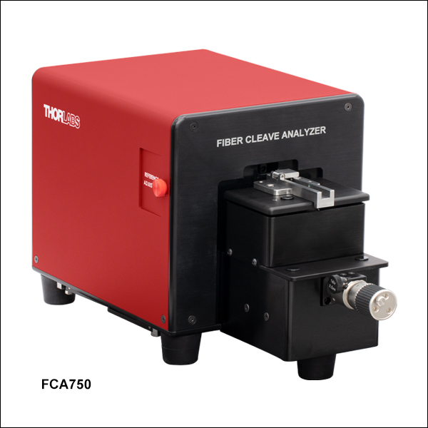
- Automated, Compact Cleave Analyzer Controlled with User-Supplied PC
- Automatic Measurements of Fiber Diameter and Cleave Angle
- Inspect Fibers with Claddings from Ø80 µm to Ø750 µm
- Included Ceramic Inserts for Ø177 µm - Ø320 µm or Ø346 µm - Ø795 µm Fiber
FCA750
Fiber Cleave Analyzer
Cleave Analyzer Software


Please Wait
| Item # | FCA750 |
|---|---|
| Fiber Cladding Diameter Range | 80 to 750 µm |
| Image Sensor | 1/1.8" CMOS, 8 Bit, 8.3 MP |
| Resolution | 0.4 µm |
| Internal LED Wavelength | 610 nm |
| Field of View | 1440 µm x 810 µm |
| Cleave Angle Range | 0 to 2° |
| Cleave Angle Resolution | 0.1° |
| Dimensions (W x H x D) | 6.15" x 6.79" x 14.66" (156.2 mm x 172.5 mm x 372.4 mm) |
| Mass (Weight) | 13.1 lbs (6 kg) |
| Power Supply | DS12 |
| Computer Interface | USB 3.0 Type-C |
| Included Fiber Inserts | ||
|---|---|---|
| Item # | Accepted Diameters (Min/Max) | |
| VHC250 | 177 µm / 320 µm | |
| VHC500 | 346 µm / 795 µm | |
特長
- 全自動、非接触でクリーブ後のファイバ素線の分析が可能
- クラッド径Ø80 µm~Ø750 µmのファイバを検査可能
- クリーブの平坦度を素早く確認
- 2種類の自動測定モード:ファイバ径の測定(Inspect View)、またはクリーブ角度の測定(Fringe View)
- Ø177 µm~Ø320 µmまたはØ346 µm~Ø795 µmのファイバに対応する交換用セラミックインサートが付属
- Ø177 µm~Ø3198 µmのファイバ用インサート(下記にて別売り)が使用可能
- お手持ちのPCへのクリーブアナライザ用ソフトウェアのインストールが必要(「ソフトウェア」タブ参照)
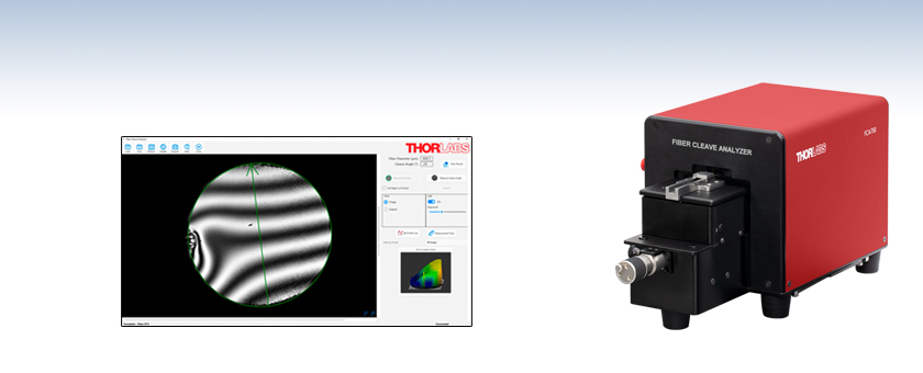
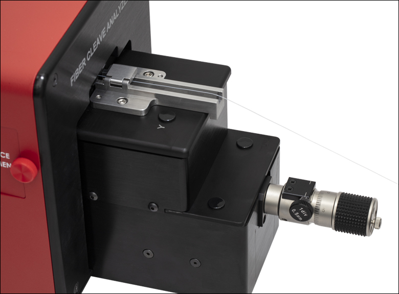
当社のファイバークリーブアナライザFCA750は、クラッド径Ø80~Ø750 µmのクリーブ後のファイバ素線の平坦度ならびに平面品質をチェックすることができる干渉測定システムです。
Click to Enlarge
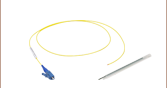
Figure 1.1 Ø250 µm用ファイバーインサートに取り付けられたファイバ素線
こちらのアナライザを使用して、クリーブしたファイバ端面の外観検査や、ファイバ径およびクリーブ角度の自動測定が可能です。大径ファイバ用クリーバLDC401、LDC450Bのようなファイバークリーバと組み合わせて、クリーブパラメータの設定を補助し、クリーバの性能を検証することができます。
アナライザFCA750には、Ø177 µm~Ø320 µmファイバ用セラミックファイバーインサートVHC250(Figure 1.1参照)、Ø346 µm~Ø795 µmファイバ用インサートVHC500ならびにアライメントツールが付属します。ファイバーインサートVHC250およびVHC500はセラミック製で、後方反射を最小限に抑え、アナライザの性能を最適化します。付属のファイバーインサートVHC250、VHC500は、GPXシリーズファイバ加工機、 クリーバ内蔵型GPXシリーズファイバ加工機、ファイバークリーバLDC401シリーズおよびLDC450B、ファイバ前処理ステーションFPS301、ファイバ融着接続機LFS4100に対応します。また、このアナライザは、上記のすべてのファイバ加工機や測定システム、ならびにCO2レーザ光ファイバ加工機ワークステーションGPX4000LZに対応する直径Ø177 µm~Ø3198 µmのファイバ用インサート(下記参照)と使用することもできます。すべての移動用インサートには移動用クランプVHT1(下記参照)が必要です。移動用インサートに外径が550 µmより小さいファイバを使用する場合には、V溝付きグラファイト(下記参照)も必要となります。
このアナライザは、標準的なUSB 3.0ポート付きのPC(付属しておりません)に接続する必要があります。
付属のインサートと、対応する移動用インサートには、直径200 µm未満の小径ファイバを設置するための真空穴があります。これを補助するため、アナライザの背面には、お手持ちの他社製の補助ポンプを取り付けるための外径5/32インチのチューブ用真空ポートが付いています(詳細は「前面&背面パネル」タブをご参照ください)。最終到達圧力-27 kPa(ゲージ圧)以下、最小フローレート5 L/minの真空ポンプの使用を推奨いたします。
ソフトウェアインターフェイス
ソフトウェア(「ソフトウェア」タブからダウンロードいただけます)には、Inspect ViewとFringe Viewの2種類があります。Inspect Viewでは、ファイバ径を自動で測定します。測定ツールを追加して、ファイバのコア径やストレスロッド(応力付与ロッド)径などのその他のファイバ特性を手動で測定することもできます。高解像度、高コントラストの画像により、ファイバ端面の外観検査を行い、スクライブの跡や毛羽立ち、埃などの欠陥を検出することもできます。Fringe Viewでは、高コントラストの干渉縞により、クリーブ角度を自動測定し、端面の高解像度画像を生成します。詳細は「ソフトウェア」タブをご覧ください。
前面&背面パネル
Click to Enlarge
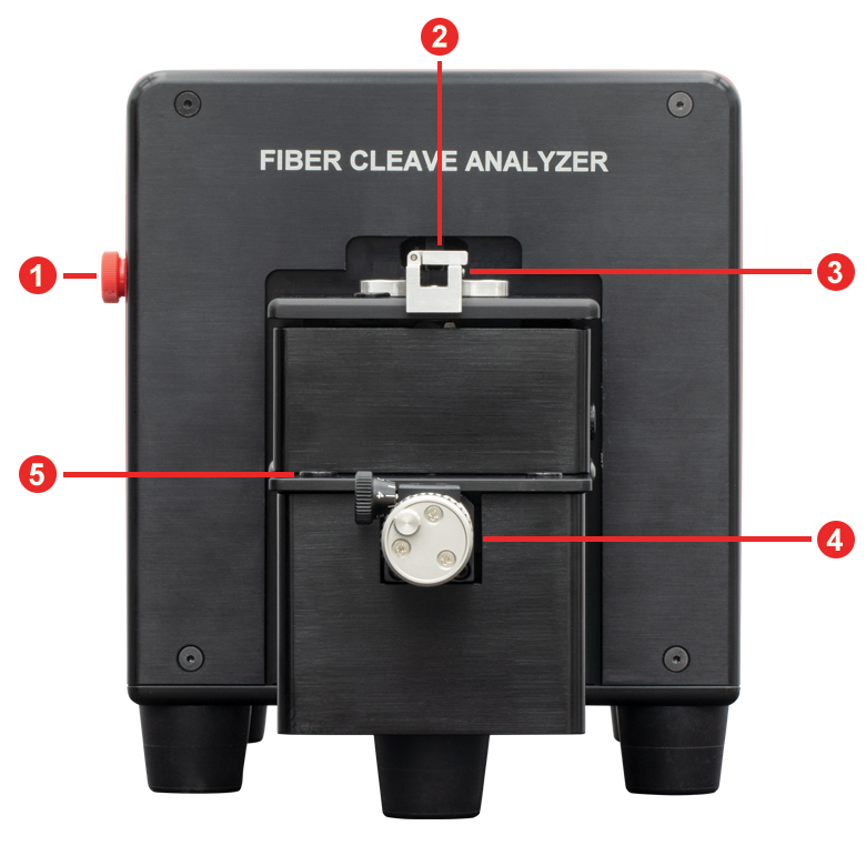
前面パネル
Click to Enlarge
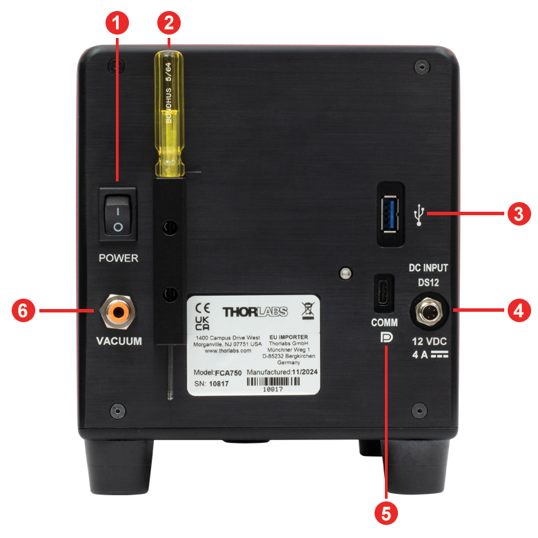
背面パネル
| Front Panel | |
|---|---|
| Callout | Description |
| 1 | Reference Adjustment Door |
| 2 | Fiber Clamp |
| 3 | Fiber Mount |
| 4 | Focus Adjust Micrometer |
| 5 | Vertical Adjustment Access Port |
| Back Panel | |
|---|---|
| Callout | Description |
| 1 | Power Switch |
| 2 | Tool Holder for a 5/64" Balldriver and a 0.035" Hex Key |
| 3 | For Future Use |
| 4 | Power Connector |
| 5 | USB Type-C Port for Computer Connection |
| 6 | Vacuum Port for 5/32" OD Tubing |
ソフトウェア
バージョン1.0.3
ボタンをクリックするとFCA750用ソフトウェアのページをご覧いただけます。
| Table 3.1 Minimum Requirements | |
|---|---|
| Operating System | Windows® 10 or Windows 11 |
| Processor (CPU) | 1.5 GHz |
| Memory (RAM) | 2 GB |
| Interface | Super Speed USB 3.0 Port |
| Display | 1024 x 768 |
ファイバークリーブアナライザFCA750を使用する際は、測定ソフトウェアプログラム(Softwareのリンクをクリックしてダウンロードいただけます)を、USB 3.0ポート付きでWindows®10またはWindows 11を搭載したお手持ちのPCにインストールする必要があります。このソフトウェアでは、Inspect ViewとFringe Viewの2種類のモードをご利用いただけます。Inspect Viewでは、ファイバ径を自動測定できます。測定ツールを追加して、ファイバのコア径やストレスロッド(応力付与ロッド)径などのその他のファイバ特性を手動で測定することもできます。高解像度、高コントラストの画像により、ファイバ端面の外観検査を行い、スクライブの跡や毛羽立ち、埃などの欠陥を検出することもできます。Fringe Viewでは、高コントラストの干渉縞により、クリーブ角度を自動測定し、端面の高解像度画像を生成します。
Inspect ViewとFringe View
Click to Enlarge
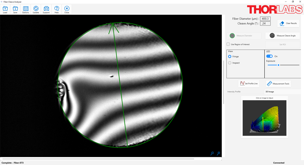
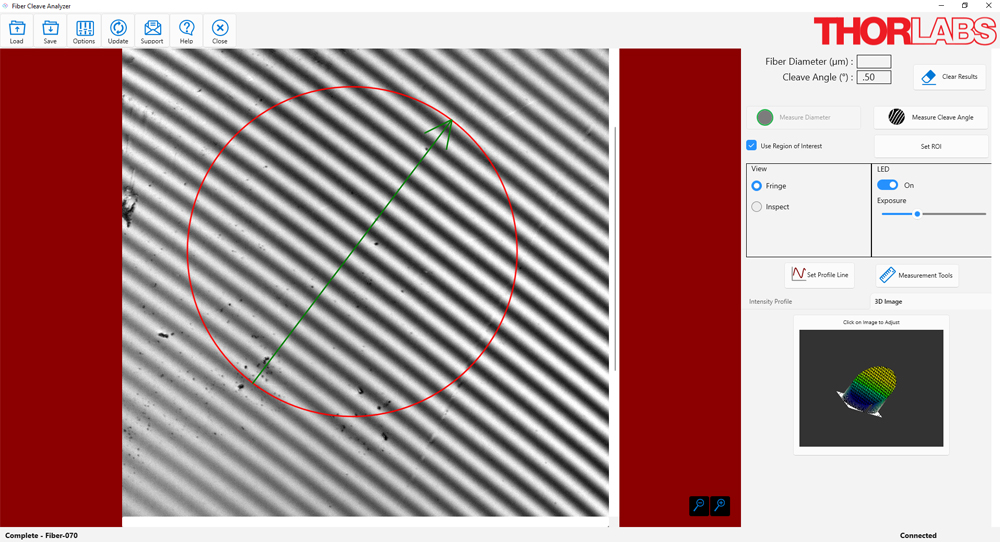
Figure 3.3 Fringe Viewでは、高コントラストの干渉縞により、クリーブ角度を自動測定し、端面の高解像度画像を生成します。
Click to Enlarge
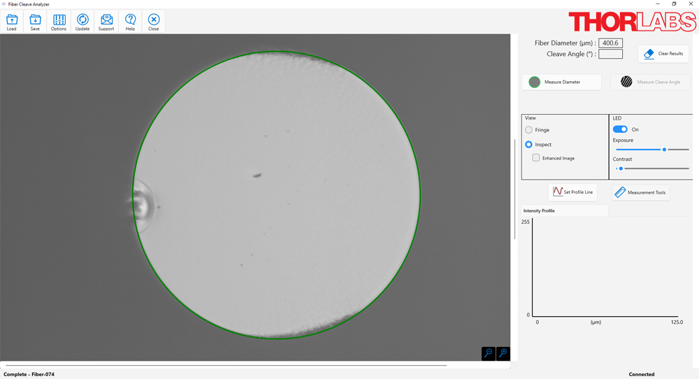
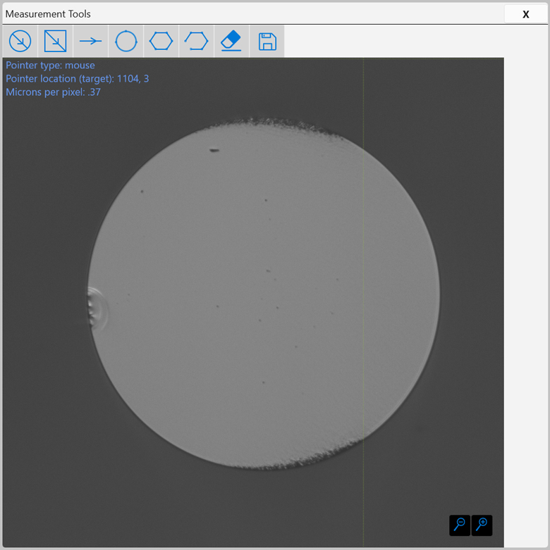
Figure 3.2 Inspect Viewでは、ファイバ径を自動で測定します。測定ツールを追加して、ファイバコアやストレスロッド(応力付与ロッド)などのファイバ特性を手動で測定することもできます。高解像度、高コントラストの画像により、ファイバ端面の外観検査を行い、スクライブの跡や毛羽立ち、埃などの欠陥を検出することもできます。
Click to Enlarge
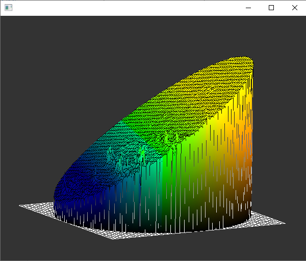
Figure 3.4 ファイバ端面の3D表示
測定ツール
Click to Enlarge
Figure 3.5 測定ツール
測定ツールのボタンを選択すると、新しいウィンドウが開き、キャプチャされたファイバの画像が表示されます(Figure 3.5参照)。このウィンドウには、手動測定を支援するツールが多数用意されています。
円形ツール
円形ツールを使用してファイバ端面の円形特性を測定します。
方形ツール
方形ツールを使用してファイバ端面の方形特性を測定します。
線形ツール
線形ツールを使用して線形特性を測定します。
3点円形ツール
円周上の3点を選択して円を定義します。
多角形ツール
多角形の頂点をクリックして多角形を定義します。終了するには、最初の頂点をクリックします。
非線形ツール
非線形特性を測定します。形状を定義するために必要な数の点をクリックします。それが終わったら、チェックマークをクリックします。
消去ツール
最後に描いたオブジェクトを消去します。再度選択すると、前回描画したオブジェクトが消去されます。
保存
保存を選択すると、現在表示されているオーバーレイと一緒に画像を保存できます。
システムアライメントの検証
Click to Enlarge
Figure 3.8 このソフトウェアを使用して付属のアライメントツールのクリーブ角度を測定することで、システム内部の光学素子のアライメントを検証できます。測定された角度は、アライメントツールに記録された角度から±0.1°以内でなければなりません。そうでない場合は、光学系を再アライメントする必要があります。
Click to Enlarge
Figure 3.6 アナライザFCA750にはアライメントツールが付属しています。

Click to Enlarge
Figure 3.7 アナライザFCA750にアライメントツールを取り付けた様子
アナライザが測定したクリーブ角度はシステム内部の光学素子のアライメントに依存します。付属のアライメントツールの角度を測定することで、アライメント状態を検証できます(Figure 3.6参照)。アライメントを検証するには、まず、アライメントツールをファイバーマウントに挿入します(Figure 3.7参照)。ソフトウェアのFringe Modeを選択し、画像をズームアウトしてカメラ画像全体を表示します。フォーカスマイクロメータを使用して、良好なコントラストの干渉縞を取得します(Figure 3.8参照) 関心領域(ROI)オプションを有効にして、領域をターゲットの中心に定義して、Measure Cleave Angleを選択します。測定された角度は、アライメントツールに記録された角度から±0.1°以内でなければなりません。そうでない場合は、光学系を再アライメントする必要があります。Options/SetupタブからAlignmentを選択すると、この手順が表示されます。
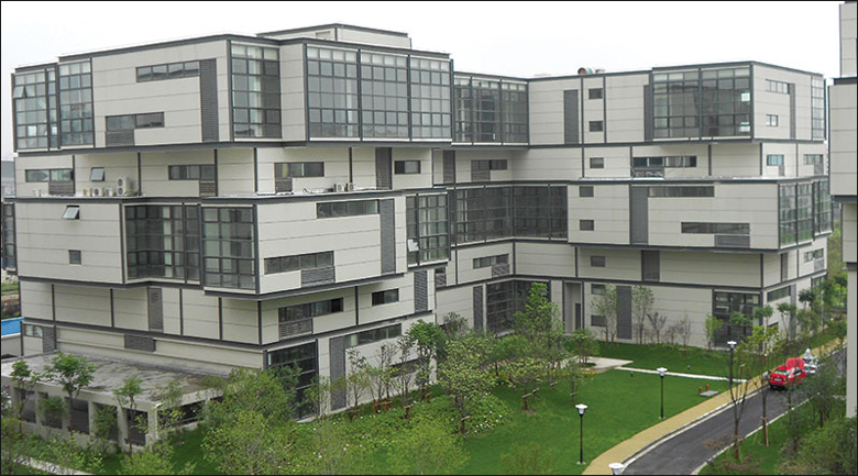
 Product DemonstrationsThorlabs has demonstration facilities for the Vytran® fiber glass processing systems offered on this page within our Morganville, New Jersey; Shanghai, China; and Exeter, Devonshire offices. We invite you to schedule a visit to see these products in operation and to discuss the various options with a fiber processing specialist. Please schedule a demonstration at one of our locations below by contacting technical support. We welcome the opportunity for personal interaction during your visit! Thorlabs Vytran Europe
|

.jpg)
| Posted Comments: | |
| No Comments Posted |

 ズーム
ズーム付属品
Click to Enlarge
アナライザFCA750にはアライメントツールが付属しています。
- 全自動、非接触でクリーブ後のファイバ素線の分析が可能
- クラッド径Ø80 µm~Ø750 µmのファイバを検査可能
- ファイバ径またはクリーブ角度を自動で測定
ファイバークリーブアナライザFCA750は、クリーブ済みファイバ素線の平坦度ならびに平面品質をチェックすることができる干渉測定システムです。Inspect ViewおよびFringe Viewの2種類のモードをご使用いただけます。Inspect Viewでは、ファイバ径を自動で測定します。測定ツールを追加して、ファイバコアやストレスロッド(応力付与ロッド)などのファイバ特性を手動で測定することもできます。高解像度、高コントラストの画像を使用して、ファイバ端面の外観検査を行い、スクライブの跡や毛羽立ち、埃などの欠陥を検出することもできます。Fringe Viewでは、高コントラストの干渉縞を使用してクリーブ角度を自動測定し、端面の高解像度画像を生成します。アナライザFCA750はクラッド径80~750 µmのファイバを検査できます。 アナライザFCA750には、Ø177~Ø320 µmファイバ用セラミックファイバーインサートVHC250、Ø346~Ø795 µmファイバ用インサートVHC500ならびにアライメントツールが付属します。VHF、VHDおよびVHEシリーズのファイバーホルダーインサート(下記参照)と使用することもできます。
大径ファイバ用クリーバLDC401、大径ファイバ用ポータブルクリーバLDC450Bのようなファイバークリーバと使用して、クリーブパラメータの設定を補助し、クリーバの性能を検証することができます。

 ズーム
ズーム| Table G2.1 Fiber Holder Inserts | |||||
|---|---|---|---|---|---|
| Item # | Transfer Insert |
Material | Side 1 Min/Max Accepted Diameter |
Side 2 Min/Max Accepted Diameter |
Vacuum Holes |
| VHC250a | No | Ceramic | 177 µm / 323 µm | N/A | Yes |
| VHF250 | Yesb | Stainless Steel | |||
| VHD400 | No | 279 µm / 519 µm | N/A | Yes | |
| VHF400 | Yesb | ||||
| VHD500 | No | 346 µm / 795 µm | N/A | Yes | |
| VHC500a | No | Ceramic | |||
| VHF500 | Yesb | Stainless Steel | |||
| VHD750 | No | 516 µm / 1047 µm | N/A | Yes | |
| VHF750 | Yesb | ||||
| VHE10 | No | 773 µm / 1271 µm | 1034 µm / 1523 µm | No | |
| VHE15 | No | 1280 µm / 1769 µm | 1534 µm / 2007 µm | No | |
| VHE20 | No | 1787 µm / 2267 µm | 2033 µm / 2513 µm | No | |
| VHE25 | No | 2270 µm / 2844 µm | N/A | No | |
| VHE30 | No | 2692 µm / 3198 µm | N/A | No | |
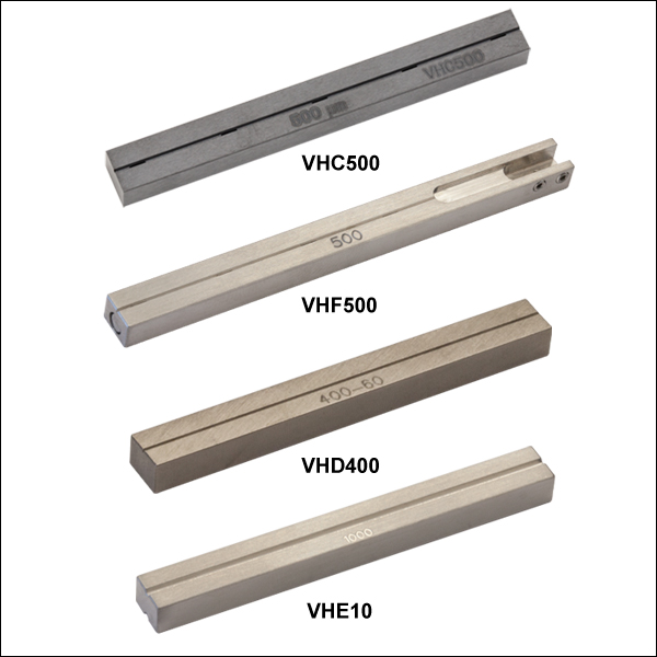
- Fiber Holder Inserts with V-Grooves for Fibers with Coating Diameters from 177 µm to 3198 µm
- Ceramic Inserts Provide Lower Reflectivity than Equivalent Stainless Steel Inserts for Small Fiber Sizes (Claddings <250 µm)
- Transfer Inserts Enable the Movement of Fibers Between Compatible Systems:
- FCA750 Fiber Cleave Analyzer
- LDC401 Series and LDC450B Fiber Cleavers
- GPX Fiber Processors and GPX Fiber Processors with Integrated Cleavers
- FPS301 Fiber Preparation Station
- LFS4100 Fusion Splicer
- Single-Sided Inserts have Vacuum Holes for Aligning Fibers in the V-Groove
- VHC250 and VHC500 Ceramic Fiber Holder Inserts are Included with the FCA750 Fiber Cleave Analyzer
When using the FCA750 Fiber Cleave Analyzer, a fiber holder insert and the FCA750 Analyzer clamping lid can be used to prevent axial or rotational movement of the fiber. One VHC250 and one VHC500 Ceramic Fiber Holder Insert are included with the cleave analyzer. Additional ceramic or stainless steel fiber holder inserts are also available for purchase separately.
Fiber holder inserts are typically used to hold the fiber coating, which is usually significantly larger than the cladding; accepted diameters for each insert are provided in Table G2.1.
Ceramic Fiber Holder Inserts (Item #s beginning with VHC) are made of ceramic to minimize back reflection into the FCA750 Cleave Analyzer, which improves the contrast of the fringe pattern as compared to using similar stainless steel inserts. This is particularly helpful when examining the end face of fibers with claddings <250 µm.
Fiber Holder Transfer Inserts (Item #s beginning with VHF), when used with the VHT1 Transfer Clamp, allow for a single fiber to be transferred between the FCA750 Fiber Cleave Analyzer, LDC401 or LDC450B Fiber Cleavers, FPS301 Stripping and Cleaning Station, LFS4100 Splicing System, and the GPX3400 Glass Processing Workstation with minimal loss of alignment. For example, a fiber can be placed in a transfer insert and cleaved using the LDC401 cleaver. Then, the entire transfer insert can be placed in the FCA750 Fiber Cleave Analyzer for quality control and, finally, moved to the LFS4100 Splicing System for splicing. This process works because the transfer inserts are precisely located within each system, and the VHT1 Magnetic Lid (sold below) prevents movement of the fiber during transport. All of these transfer inserts require the VHT1 Transfer Clamp (sold below); transfer inserts for fiber outer diameters ≤550 µm also require a Graphite V-Groove (sold below).
Ceramic fiber holder inserts (Item #s beginning with VHC), stainless steel bottom inserts (Item #s beginning with VHD), and stainless steel fiber holder transfer inserts (Item #s beginning with VHF) have vacuum holes to help position the fiber in the groove. Using vacuum suction is recommended to position fibers with diameters <200 µm, but some users also find this feature helpful for fibers with an outer diameter up to 1.047 mm. To support this, the FCA750 Fiber Cleave Analyzer includes a vacuum port that accepts 5/32" OD tubing on the back of the system to attach an optional user-supplied third-party auxiliary pump (see the Front & Back Panels tab for more details). Using a vacuum pump with an ultimate base pressure of -27 kPa or lower and a minimum flow rate of 5 L/min is recommended.
The VHE series of fiber holder bottom inserts have a V-Groove on one (VHE25 and VHE30) or both sides (VHE10, VHE15, and VHE20), but do not include vacuum holes.
")
 ズーム
ズーム| Table G3.1 V-Groove Sizes | |||||
|---|---|---|---|---|---|
| Item # | Accepted Diametera (Min / Max) | Groove Length | |||
| VHG125 | 80 µm / 125 µm | 0.313" | |||
| VHG125L | 80 µm / 125 µm | 0.594" | |||
| VHG200 | 150 µm / 200 µm | 0.313" | |||
| VHG250 | 200 µm / 250 µm | 0.313" | |||
| VHG250L | 200 µm / 250 µm | 0.594" | |||
| VHG300 | 250 µm / 300 µm | 0.313" | |||
| VHG350 | 300 µm / 350 µm | 0.313" | |||
| VHG400 | 350 µm / 400 µm | 0.313" | |||
| VHG450 | 400 µm / 450 µm | 0.313" | |||
| VHG500 | 450 µm / 500 µm | 0.313" | |||
| VHG500L | 450 µm / 500 µm | 0.594" | |||
| VHG550 | 500 µm / 550 µm | 0.313" | |||
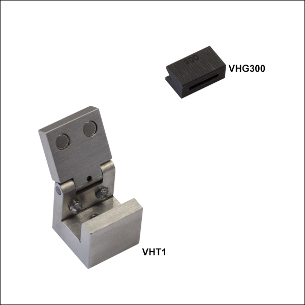
- ファイバをシステム間で移動させる際、移動用インサートと共に使用されるクランプならびにV溝付きグラファイト
- 各移動用インサートには、この移動用クランプVHT1が1つ必要
- 移動用クランプは、GPXシリーズ ファイバ加工機、ファイバークリーバLDC401シリーズおよびLDC450B、ファイバ前処理ステーションFPS301、融着接続機LFS4100、ファイバークリーブアナライザFCA750に対応します。
- V溝付きグラファイトは外径Ø550 µm以下のファイバに対応
- V溝は外径80 µm~550 µmのファイバに対応
こちらの移動用クランプとV溝付きグラファイトは、上記のVHFシリーズ用底部インサートと一緒に使用されるためのもので、システム間でファイバを移動させる際に再アライメントを最小限に抑えます。例えば、ファイバを移動用インサートに入れ、ファイバークリーバLDC401を使用してクリーブします。その後、ファイバが入っている移動用インサートごとクリーブアナライザに移動させてクリーブ端面の品質管理を行い、ファイバ加工機で融着接続します。
クランプVHT1は、移動用インサートを磁性の蓋で固定してファイバの軸方向の移動を防止し、ファイバを触ることなくインサートを保持しながら移動します。V溝付きグラファイトは、融着接続時、外径が550 µm以下のファイバの保持をサポートします(詳細はTable G3.1をご覧ください)。ファイバ長に沿ったファイバ保持を強化したり、加工中にファイバが邪魔になるのを防ぐため、長さ15.1 mmのV溝付きグラファイトもご用意しています(型番VHG125L、VHG250L、VHG500L)。V溝付きグラファイトは、2個の止めネジ(セットスクリュ)で移動用インサートに固定できます。