 Products Home
ヒーター温度コントローラー(温度調節器)
- Heating Set Point from -200 °C to 400 °C
- Two Channels Capable of Independent or Synchronized Operation
- User-Configurable PID with Auto-Tuning Function
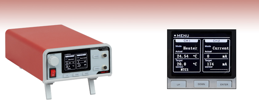
TC300B
Heater and TEC Temperature Controller
Front Panel Allows Stand-Alone Operation


Please Wait
| Specifications | |
|---|---|
| Output Power per Channel | 48 W (Max) |
| Output Current per Channel | 2 A (Max) |
| Output Voltage per Channel | 24 V (Max) |
| Temperature Setting Range | -200 to 400 °Ca |
| Set Point Resolution | 0.1 °C / 0.001 °Cb |
| Temperature Stability | ±0.1 °C |
| Sensor Types | Thermistorc, AD590, Thermocoupled, 2-Wire and 4-Wire Platinum 100 Ω, 2-Wire and 4-Wire Platinum 1000 Ω |
| Output Connector Type | Hirose HR10A-7R-6S(73) |
| USB Interface | USB 2.0 Type-B |
| Power Supply | 100 - 240 VAC, 50 - 60 Hz, 165 VA Max |
| Operating Temperature | 0 - 40 °C |
| Storage Temperature | -15 - 65 °C |
| Dimensions (H x W x D) | 86.6 mm x 154.3 mm x 327.8 mm (3.41" x 6.07" x 12.91") |
| Weight | 1.7 kg |
Features
- Dual-Channel Resistive Heater Controller
- Can Drive Resistive Heating Elements and Thermoelectric Cooler (TEC) Devices
- Three Control Modes
- User-Configurable, Closed-Loop PID Control with Auto-Tuning Function
- Constant-Current, Open-Loop Operation
- Cycle Mode for Executing User-Defined, Closed-Loop Ramp and Hold Procedures
- High-Resolution Temperature Measurement and Control Available When Using NTC Thermistors
- Run Standalone, via PC Software, or via C/C++ and Labview SDKs
- Compatible 6-Pin Hirose Cables Available:
- 3.0 m (9.84') HR10CAB1 Male-to-Male Cable
- 1.8 m (5.90') HR10AD1 Cable with Breakout Box for Custom Applications
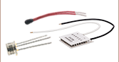
Thorlabs' TC300B Heater and TEC Temperature Controller is a general-purpose benchtop controller intended for use with resistive heating elements, including foil (such as Item # HT10K) and resistive coil (such as Item # HT15W) types. It also accepts feedback from a variety of temperature sensor types including positive (such as Item # TH100PT) or negative (such as Item # TH10K) temperature coefficient thermistors and thermocouples with a resolution of 0.1 °C. When configured with negative temperature coefficient (NTC) thermistors, a high-resolution mode offers temperature resolution of 0.001 °C.
The two channels of the TC300B controller are capable of either independent or synchronized operation. Each channel has PID control with programmable P, I, and D gains as well as an auto-tune function. The back of the TC300B controller has connectors for analog inputs and outputs as well as output triggers for each channel. An output proportional to the actual temperature of the channel is given in the analog output, and the input and output trigger allows the user to enable or disable the channel. For more information, please see the Front & Back Panel tab.
User-programmable maximum temperature and current/voltage limits protect the connected heating element from being overheated or over driven. Other safety features include an Open Sensor Alarm that will shut down the driver if the temperature sensing element is missing or becomes disconnected.
A simple keypad interface allows stand-alone operation, but the TC300B controller can also be connected to a PC using the included USB Type-B cable and our TC300B Software. Interfacing with a PC can also be achieved by using LabVIEW® or LabWindows with a simple command-line interface from any terminal window. Please see the Software tab for more information.
The TC300B heater controller uses female Hirose connectors to read the temperature of the heating element and supply current. Please note that the cable for connecting this heater controller to a heating element is not provided; we recommend the HR10CAB1 Male-to-Male Hirose Connector Cable or the HR10AD1 Hirose Connector Cable with Breakout Box, both sold separately below. For the pin assignments needed to adapt the TC300B controller to your heater, please see the Front & Back Panel tab.
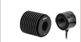
前面パネル

チャンネル1およびチャンネル2のHirose製コネクタ
HR10A-7R-6S(73)
| Callout | Connection | Callout | Connection |
|---|---|---|---|
| 1 | LCD Screen | 5 | Enable/Disable Button for Channel 1 |
| 2 | Adjustment Knob | 6 | Hirose Connector for Channel 1 |
| 3 | Power Switch | 7 | Enable/Disable Button for Channel 2 |
| 4 | Keypads | 8 | Hirose Connector for Channel 2 |
| Pin | Assignment |
|---|---|
| 1 | Heater/TEC Output Positive |
| 2 | Heater/TEC Output Negative |
| 3 | Sensor Positive (4-Wire PT100/PT1000 Only) |
| 4 | Sensor Positive |
| 5 | Sensor Negative |
| 6 | Sensor Negative (4-Wire PT100/PT1000 Only) |
背面パネル

TRIG1&TRIG2
BNCメス
+5 V CMOS
入力に設定されている場合:+ 5 V入力でチャンネルが有効になり、0V入力で無効になります。
出力に設定されている場合:チャンネルが有効の時に+5 Vを出力し、無効の時に0 Vを出力します。
ANLG1&ANLG2
BNCメス
0~+5 V、インピーダンス20 kΩ
各チャンネルの実際の温度に比例する信号を出力:0 Vは最低設定温度に対応し、+ 5Vは最高設定温度に対応します。
| Callout | Connection | Callout | Connection |
|---|---|---|---|
| 1 | Analog Output of Channel 1 (ANLG1) | 5 | Analog Output of Channel 2 (ANLG2) |
| 2 | AC Input Connector | 6 | Cooling Fan |
| 3 | Trigger of Channel 1 (TRIG1) | 7 | Trigger of Channel 2 (TRIG2) |
| 4 | USB Type B Connector | 8 | Mono Jack for External Sensor |
外部センサ用コネクタ
2.5 mmモノラルジャック

2.5 mmのステレオイヤホンジャックに対応。コントローラTC300Bは最大抵抗999 kΩまでのサーミスタに対応します。
PC接続
USB Type B
USB Type Bケーブルが付属
The TC300B controller is compatible with thermistors such as the TH10K thermistor as well as PT100 (such as Item # TH100PT) and PT1000 types of Platinum Resistance Temperature Detectors. The following specifications are used for determining the set-point and read back values for these types of thermistors and sensors.
Thermistors
When a thermistor is wired to one of the Hirose connectors on the front panel and the type is set to NTC1 or a thermistor is plugged into the External Sensor port on the back panel and the type is set to EXT1, the TC300B controller measures the resistance value of the thermistor and calculates the temperature based on the “Beta” formulas defined below.R = R0 * eβ[(1/T) - (1/T0)]
R is the resistance in Ω at temperature T
R0 is the nominal resistance in Ω at temperature T0
β is the constant associated with the particular thermistor
T is the temperature in K
T0 is the nominal temperature (usually 298.15 K = 25 °C)
The TC300B controller allows users to set the values of β, R0, and T0. For different thermistors, the actual value of these parameters can vary and can usually be found on their datasheets.
When a thermistor is wired to one of the Hirose connectors on the front panel and the type is set to NTC2 or a thermistor is plugged into the External Sensor port on the back panel and the type is set to EXT2, the TC300B controller also supports the Steinhart-Hart method to approximate the relation between temperature and thermistor resistance, defined by the following formula:
1/T = A + B * ln(R) + C * (ln(R))3
T is the temperature in K
R is the resistance in Ω at temperature T
A, B, and C are Steinhart-Hart parameters
The TC300B controller allows user input of the A, B, and C parameters. For thermistors that support the Steinhart-Hart method, the actual value of A, B, and C can usually be found on their datasheets.
PT100 and PT1000 Sensors
When the sensor type is set to PT100 or PT1000, the TC300B controller measures the resistance and calculates the temperature of the PT100 or PT1000 platinum resistance temperature detector using the following formula:
R = R0 (1 + A * T + B * T2)
(In accordance with IEC 751, 2:1995-07 [DIN EN 60751; 1996-07])
A = 3.9083 x 10⁻³ °C-1
B = -5.775 x 10⁻⁷ °C-2
R is the resistance in Ω at temperature T
T is the temperature in K
R0 = 100 Ω for the PT100
R0 = 1000 Ω for the PT1000
The TC300B controller supports 2- and 4-wire connections for both PT100 and PT1000 sensors. When the sensor type is set to PT100 or PT1000, select the “Parameter” option to toggle between the 2-wire and 4-wire connection setting.

Click to Enlarge
Software GUI
Software
Version 2.0.0
Software package to operate the TC300B including a GUI, drivers, and LabVIEW®/C++/Python SDK for third-party development.
Software for the TC300B Heater and TEC Temperature Controller
Thorlabs provides a software package for the TC300B Heater and TEC Temperature Controller which provides access to all functionality of the controller from a PC interface. After installing the software package and connecting the host PC to the TC300B controller via USB, the PC can control the TC300B controller using either the software GUI or through a command-line interface.
The GUI’s controls duplicate all front-panel functions like setting the sensor parameters, setting the output control scheme (PID, constant current, cycle), and enabling or disabling the output. Additionally, the software allows for data logging of temperature, output current, and output voltage for both channels to a .csv file.
The software GUI and front panel controls are enabled simultaneously (i.e. any adjustments made to the TC300B controller using the front panel are used to update the GUI in real time).

Click to Enlarge
Contents in the Package of the TC300B Heater and TEC Temperature Controller
The following items are included in the TC300B Heater and TEC Temperature Controller package:
- TC300B Heater and TEC Temperature Controller
- Regional Power Cord
- USB Type-B Cable, 2 m (79") Long
- Quick Start Guide
PIDの基礎
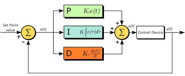
PID回路は制御ループフィードバックコントローラとしてよく用いられており、さまざまなサーボ回路として広く使われています。 PIDとは、それぞれ比例(Proportional)、積分(Integral)、微分(Derivative)の頭文字で、PID回路の3つの制御設定を表しています。 サーボ回路の役割は、システムを長時間所定値(目標値)に保持することです。 PID回路は、出力を目標値に保持するため、主に目標値と出力値の差をエラー信号として発生させることにより、システムをアクティブ制御しています。 3つの制御は、時間依存型エラー信号に関連しています; 端的に言うと、次のように考えることができます。 比例は出力値のエラー、積分は過去の累積エラー、微分はエラーの予測によっています。 各制御の結果は、その後回路の電流を調整する加重和にフィードされます(u(t))。 この出力は制御デバイスへ送られ、その値は回路へとフィードバックされ、回路の出力を目標値に到達させ保持するようアクティブ安定化の処理が行われます。 以下のブロック図は、PID回路の動作を簡略化したものです。 システム要求や要件によって、サーボ回路に1つもしくは複数の制御を使用することができます(例: P、I、PI、PD、PID)。
PID回路の適正な制御設定によって、最小限のオーバーシュート(目標値超過)とリンギング(目標値振動)で、素早い応答速度を実現できます。 ここで半導体レーザの温度安定化に用いられる温度サーボを例にとってみましょう。 PID回路は、最終的には熱電冷却素子(TEC)への電流を自動制御します(多くの場合FET回路上のゲート電圧の制御を通して行われます)。 この例では、電流は操作変数(MV)とします。 サーミスタは半導体レーザの温度モニタとして用いられ、サーミスタにかかる電圧を処理変数(PV)とします。 目標値(SP)の電圧は指定の温度に対応して設定します。 エラー信号e(t)は、SPとPVの差分を表します。 PIDコントローラはエラー信号を発生し、目標値に到達するようMVを変更させます。 例えばもし、e(t)の状態が半導体レーザの過熱を示せば、回路はTECを通してさらに電流を流すよう促します(比例制御)。 比例制御はe(t)に比例するので、半導体レーザを十分な速度で冷却できないかもしれません。 その場合、累積エラーから判断し、目標値へ到達させようと出力を調整し、回路はTECを介してさらに電流量を増加させます(積分制御)。 SPに到達すると(e(t)が0に近づくと)、回路はSPに達するのを見越してTECを通して電流を減少させます(微分制御)。
PID回路は適切な制御を保証するものではないことにご注意ください。 不適切なPID制御の設定は、回路を著しく振動させたり、制御の不安定を引き起こす可能性があります。 正しい動作は、PIDの適正な調整によって得られます。
PID理論
PID制御回路u(t)の出力を得る方程式は以下となります。
Kp= 比例利得
Ki = 積分利得
Kd =微分利得
e(t)=SP-PV(t)
ここから制御ユニットは数学的定義によって定義づけることができ、個々の制御についてもう少し詳しく考察することができます。 比例制御は、エラー信号に比例します。これは、回路が発生させたエラー信号に対する直接的な応答です。
より大きな比例利得は、より大きな変化をエラーへの応答にもたらし、コントローラがシステムの変化に応答できる速度に影響を与えます。 比例利得の値が高いと回路の応答を素早く行えますが、あまりに高い場合は、SP値に対して振動を引き起こしてしまいます。 値が低すぎる場合は、回路はシステム変更への応答性が悪くなります。
積分制御は、比例利得よりさらに1段階ステップが進み、エラー信号の大きさだけでなく、エラーの期間にも比例しています。
積分制御は、比例制御のみによる定常誤差を除去するとともに、回路の応答速度向上に非常に高い効果をもたらします。 積分制御は、未修正の過去のエラーを合計し、エラーにKiを乗算することで、積分応答を出します。 従ってわずかな継続エラーに対しても、大規模な集積積分応答を実現することが可能です。 しかしながら、積分制御の高速応答に起因して、高い利得値による目標値の著しい超過が生じ、振動と不安定性を引き起こします。 低すぎる場合、回路のシステム変更への応答速度が著しく低下します。
微分制御は、比例制御および積分制御から予測される目標値超過とリンギングを低減させます。 回路が時間の経過とともにどう変化しているか(エラー信号の微分から判断)素早く決定し、Kdを乗算することで微分応答を出します。
比例や積分制御と異なり、微分制御は回路の応答を減速させます。 そのため、積分制御や比例制御によって引き起こされた振動を抑制したり、超過を部分的に補うことができます。 高い利得値は回路の応答性にかなりの減速を生じさせ、ノイズや高周波振動が発生しやすくなります(回路が迅速に応答するには低速すぎるため)。 低すぎると、回路はSP値を超過する傾向にあります。しかしながら、SP値を著しく超過するケースは避けなければならず、そのためより高い微分利得(より低い比例利得とともに)が用いられます。 下記の図は、個々のパラメータの利得の増加による影響を示しています。
| Parameter Increased | Rise Time | Overshoot | Settling Time | Steady-State Error | Stability |
|---|---|---|---|---|---|
| Kp | Decrease | Increase | Small Change | Decrease | Degrade |
| Ki | Decrease | Increase | Increase | Decrease Significantly | Degrade |
| Kd | Minor Decrease | Minor Decrease | Minor Decrease | No Effect | Improve (for small Kd) |
チューニング
通常、適切なサーボ制御を得るために、P、I、Dの利得値は個々で調整する必要があります。 どのシステムに対してもどの値にするべき、といった決まった一連のルールがあるわけではありませんが、基本手順に沿ったチューニングは各々のシステムや環境に合わせるのに役立ちます。 概して、PID回路はSP値の超過をわずかに起こし、その後SP値に到達させるため素早く減衰するようにします。
手動による利得設定のチューニングは、PID制御設定において最もシンプルな方法です。 しかしながらこの手順はアクティブで行われ(PIDコントローラがオンとなり、システムに正しく接続されている)、完全に設定するには多少の経験を要します。 PIDコントローラを手動で調整するには、まず始めに積分および微分利得を0に設定します。 出力に振動が現れるまで、比例利得を上げてください。 比例利得はこの値の約半分の値に設定します。 比例ゲイン利得設定後は、任意のオフセットがシステムに合わせた適切なタイムスケールに修正されるまで積分利得を上げてください。 上げすぎた場合は、SP値の著しい超過と回路の不安定性が引き起こされます。 積分利得が設定されたら、次に微分利得を上げてください。 微分利得はオーバーシュートを軽減し、システムを迅速にSP値へ収束させます。 微分利得を上げすぎると、大幅な超過が生じます(回路の応答が低速すぎるため)。利得設定を試行することにより、システムが変化へ素早く応答し、SP値の振動を効率よく減衰させるといった、PID回路の性能を最大限にすることができます。
| Control Type | Kp | Ki | Kd |
|---|---|---|---|
| P | 0.50 Ku | - | - |
| PI | 0.45 Ku | 1.2 Kp/Pu | - |
| PID | 0.60 Ku | 2 Kp/Pu | KpPu/8 |
手動によるチューニングは非常に効果的なPID回路の設定方法ですが、ある程度の経験とPID回路および応答についての理解を必要とします。 PIDチューニングのためのZiegler-Nicholsメソッドは、もう少し体系的な手引きとなっています。 再び、積分利得と微分利得をゼロ値にセットしてください。 比例利得を回路が振動するまで上げます。 この利得をレベルKuと呼びます。 振動はPuの期間です。 個々の制御回路の各利得は右の表に示しています。
| Posted Comments: | |
Ken Libbrecht
(posted 2024-08-14 10:56:52.173) Excellent product, but the analog output (ANLG1) changes in one-degree increments. Is there any way to get better temperature resolution from this output? Adil Meraki
(posted 2024-08-07 11:33:38.387) The user interface is not user-friendly, and its does not provide a pleasant experience with the existing user controls. cdolbashian
(posted 2024-08-14 11:06:28.0) Thank you for your feedback! We highly value the feedback you have put forward and have conveyed it to the R&D department. user
(posted 2024-07-26 19:01:47.767) Hi, I would like to use TC300 with TH10K and HT15W. I set NTC2 because TH10K seem to support the Steinhart-Hart method. But, I got sensor errors. Should I choose NTC1?
(It seemed that TC300 read proper temperature with NTC1 setting.) cdolbashian
(posted 2024-08-01 03:26:53.0) Thank you for contacting Thorlabs. The Standard Steinhart and Hart method are used in TC300 while the ABCD parameters in the TH10K spec sheet are from a variation of the "extended" Steinhart and Hart method. Those two methods follow slightly different mathematic equations thus the parameters are not 100% compatible. We are recommending setting TC300 to NTC1 mode instead of NTC2 when using with TH10K thermistor. user
(posted 2024-03-06 03:34:01.997) I have been using this device TC300 well. Now I am going to use it as a cooler, not a heater. I need some advices. I want to achieve the temperature below -50 degrees Celsius. Is there any way to get the goal? The Peltier device or other device might be the answer in my naive thought, am I right?
Are the TEC(thermoelectric cooler)s kind of the Pelteir devices?
Are the TEC(thermoelectric cooler)s not compatible to TC300?
Please let me know the best combinations for the cooling system that I want if TC300 cannot be used.
My requirements are below.
- the compatibility with TC300
(Actually, the other options are also fine.)
- no external systems
(I want to use it in a normal environment. I mean, I don't want to be hindered by any miscellaneous obstacles. A vacuum facility is also not preferred. Imagine the case of HT24S(Metal Ceramic Heater) connected to TC300.) cdolbashian
(posted 2024-03-15 04:20:59.0) Thank you for contacting Thorlabs. TC300 is compatible with TEC elements. However, the TC300 currently can only drive the TEC as a heater and does not support the cooling function of a TEC. I have contacted you directly to discuss your application further. user
(posted 2024-01-16 13:24:33.88) Dear Sirs
I am interested to build an user programmable hot plate by using your temperature controller TC300 coupled to a ceramic heater. Is it possible to program simple temperature time varying function such as linear ramp (0.5 °C/hour) directly from the front panel or from the thorlabs software? Do you have a manual for the thorlabs software? How does the software work? jdelia
(posted 2024-01-25 12:57:48.0) Thank you for contacting Thorlabs. The TC300's front panel can control the heating elements in heater or current mode. There is a "Sequence” function in the software of the TC300, which can set the temperature value in each step. You can also program this function from TC300 software. The software manual and LabVIEW/C++ /Python SDK example can be found by clicking the "Help" button within the software application. user
(posted 2023-09-22 14:14:36.367) The voltage and current limit does not work. cdolbashian
(posted 2023-10-03 01:13:31.0) Thank you for contacting Thorlabs. We released a new version of the firmware V3.2.5 to downgrade the voltage protection level to warning, so that the TC300 will not disable its output when the overvoltage occurs. You could download the firmware update tool and the latest firmware from the following link https://www.thorlabs.com/software_pages/ViewSoftwarePage.cfm?Code=TC300&viewtab=1.
To update the controller firmware, first please connect the controller to a PC, and keep holding down the “ENTER” button when powering on the device until the device shows "INITIALIZING... Do not Power-off! Updating Now". Secondly please start the firmware update tool, select the correct COM port, and connect. Thirdly please click "Browse" to select the new firmware file. Lastly please click “Update” to start the firmware update. Please note that after the update, the current limit is the still hard limit and over current will disable the device output. user
(posted 2023-08-11 00:03:44.307) Hi Thorlabs,
I expierence a weird issue with the TC300. When i press the channel button to apply voltage, the controller just resets itself. I recorded a video, if it helpfull. Would appreciate your assistance. cdolbashian
(posted 2023-08-16 11:28:25.0) Thank you for contacting Thorlabs. We have reached out to you directly to troubleshoot this further. Michele Cotrufo
(posted 2023-06-19 11:37:03.433) I am using the TC300 together with the TH100PT.
Can you clarify which setting I should use in the TC300 when using this sensor? Can I just pick 'PT100', or should I use a different type/calibration? cdolbashian
(posted 2023-06-23 11:24:56.0) Thank you for reaching out to us with this inquiry. Yes, you can set the sensor type to 'PT100' for TH100PT as it is a 100Ohm platinum resistor. user
(posted 2023-05-12 22:10:28.16) Dear Thorlabs,
I would like to use the TC300 on a new lab laptop with windows 11. Unfortunately the software is only compatible with windows 7 and 10. Are there any possibilities to still use it on windows 11? jdelia
(posted 2023-05-18 11:57:24.0) Thank you for contacting Thorlabs. Per our experience, TC300 software will be fine to work on Win11. We will contact you for some further troubleshooting. user
(posted 2023-01-13 16:34:12.457) Dear Thorlabs Team,
I purchased the TC300 a while ago and am a little dissapointed about its limited usability.
While I understand that its primary application is to drive resistive heaters I do not understand why it does not allow for a negative set temperature. For Example, it is not possible to heat from -200 C to -195 C and keep the temperature stable via the PID. (The current mode is no solution either because it does not read out the temperature. Custom programming with the SDK is also out of the question since I don't have access to a PC at its intended location and it would also defeat the purpose of an integrated PID controller)
Also a big shortcoming is the lack of a "cooling" mode, since you already offer Single-Stage TEC Elements with matching specifications.
Those two things are in my eyes the biggest shortcomings of this device. Otherwise, it would have made for a great and versatile temperature controller with its 6-pin Hirose cable connector. Right now it is "fine".
I hope those shortcomings will be addressed with future firmware updates. jdelia
(posted 2023-01-18 10:26:03.0) Thank you for contacting Thorlabs. At the moment, the TC300 is shipped with the range of the target temperature set to 0 to 200 ⁰C by default. The lower and upper limit of this range can be extended to -200 ⁰C and 400 ⁰C respectively by changing the value of corresponding parameters in the channel setting menu. However, the default PID settings are configured for room temperature applications and thus may not be suitable when the temperature is significantly lower. Users may need to manually fine tune the P, I, and D share value in order to achieve optimum performance. We are working on a new firmware with a new feature of PID auto-tune which could help users to find the best PID settings for their application without the need of lengthy manual tuning. Unfortunately, the current hardware of TC300 does not support cooling by TEC. The development of a new generation of TC300 that are compatible with TECs are already underway. user
(posted 2022-10-24 22:22:28.837) Dear Thorlabs,
I am interested in your TC300 Temperature Controller. I hope control it with Python. Is it possible to control TC300 by Python programming? If possible, could you please offer the example files?
Thanks. cdolbashian
(posted 2022-10-31 01:02:24.0) Thank you for contacting Thorlabs. The software v1.0.0 for the TC300 contains the SDK that supports Python. The SDK manual and example can be found by clicking the "Help" button within the software application. user
(posted 2022-10-07 11:02:00.21) We experience a problem with the TC300 with long-term usage. It switches off the output automatically after about 1 week. Is there a temporal usage limit in the firmware or counters resetting? ksosnowski
(posted 2022-10-10 12:51:40.0) Thank you for contacting Thorlabs. Our TC300 does not have any temporal usage limit or counters. Your local tech support team has reached out directly to you for trouble shooting. Martin Callejo
(posted 2022-08-31 17:52:03.25) Hello,
I would appreciate some technical support.
I'm currently trying to use the TC300 to heat a vapor reference glass cell using a couple of GCH25R thorlabs cap heaters.
I'm having trouble reaching a temperature of 80deg celsius with PID=(0.04, 0.04, 0.0), tau=100ms. The system reaches 77deg and is stable to +-0.01, but the PI control is unable to correct the steady state error of aprox. 3deg.
Increasing P creates oscillations, increasing I above the P value doesn't seem to do nothing.
What are the precise definitions of the PID parameters? Does the PID algorithm have modifications to protect from overshoot?
(i would be nice to include a PID formula in the manual)
Thanks in advance! cdolbashian
(posted 2022-09-07 03:11:21.0) Thank you for contacting Thorlabs. The "P" portion of the PID loop seems appropriate, but the "I" component needs further tuning, considering increase "I" share to decrease the offset. More PID information can be found in the “PID Tutorial” tab (https://www.thorlabs.com/newgrouppage9.cfm?objectgroup_id=14852&tabname=PID%20Tutorial). Additionally, it's worth checking if the current and voltage limits are set correctly to avoid that there is not enough heating power provided by the heating element in combination with TC300 to eliminate the 3 degree offset. And to avoid dissipating too much heat into the environment at higher temperature, a better thermal isolation would be helpful. user
(posted 2022-03-09 15:32:32.593) Is it possible to use the TC300 with TEC elements such as the TECH3S? cdolbashian
(posted 2022-03-11 01:39:19.0) Thank you for contacting Thorlabs. TC300 can drive TECs like TECH3S. At current stage, TC300 can only drive the TEC as a heater and does not support the cooling function of a TEC. TED4015 would be a better choice if you require both active heating and cooling applications. Hyun Gyung Lee
(posted 2022-03-02 19:56:17.17) I'm writing this feedback to get tech support. I bought TC300 to control the temperature of LCC1111T-B. The thing is that we'd like to stabilize the temperature at 70-celsius degrees of LCC1111T-B to make a short response time, BUT it is not working. The error messages, NO LOAD and OVER VOLT, keep popping up. We can only stabilize the temperature at low degrees such as 20-celsius degrees.
Please reply as soon as possible. cdolbashian
(posted 2022-03-04 04:26:01.0) Thank you for contacting Thorlabs. The resistance value of the heater in LCC1111T-B is 38.4Ω. The current applied to the heater should be limited below 600mA to prevent the error of OVER VOLT to be triggered. We will get in touch with you directly to trouble shoot. For future tech support inquiries, please feel free to use our tech support email: techsupport@thorlabs.com. Vladimir Schkolnik
(posted 2022-01-26 15:43:04.41) Hi,
I am very interested in the TC300. I am using two old heaters to regulate the temperature read out by K-Type thermocouples. The required power is only a fraction of the TC300 capabilities, but one part needs to be controlled at a temperature up to 480°C. Is it possible to increase the software limit and display of one channel from 400°C up to this temperature (no increase in current or voltage i needed).
Look forward to hear from you
Best
Vladimir Schkolnik
--------------------------------------
Dr. Vladimir Schkolnik
Project Leader Strontium Activities
Joint Lab Integrated Quantum Sensors
Humboldt-Universität zu Berlin
Institute of Physics
Newtonstraße 15
12489 Berlin
Tel : +49 (0)30 2093 4941 / 7625
Fax : +49 (0)30 2093 4718
vladimir.schkolnik@physik.hu-berlin.de
-------------------------------------- cdolbashian
(posted 2022-02-07 09:19:25.0) Thank you for contacting us Vladimir. In heater mode, the TC300 is able to read temperatures above 400°C from the thermocouple, but cannot set the target temperature above 400°C, limited by the current firmware. In current mode, the temperature can reach 480°C, but the TC300 does not monitor the temperature on the heat load. The actual temperature could rise to a very high level that could cause harm to the heater and become a hazard to personnel. |

 ズーム
ズーム- Heating from -200 °C to 400 °C
- Run Standalone or via Software
- Programmable PID with Auto-Tuning Functionality
The TC300B Heater and Thermoelectric Cooler (TEC) Temperature Controller is a two-channel benchtop controller intended for use with resistive heating elements and thermoelectric cooler devices rated up to 48 W. User-programmable maximum temperature and current/voltage limits protect the connected heating element from being overheated or over driven. Other safety features include an Open Sensor Alarm that will shut down the driver if the temperature sensing element is missing or becomes disconnected.
Capable of standalone operation from a simple keypad interface, this controller can be interfaced with a PC using the included USB Type-B cable with our TC300B Software, LabVIEW® drivers, LabWindows drivers, or using a simple command-line interface from any terminal window.

 ズーム
ズーム
Click to Enlarge
Hirose製コネクタ オス型

Click to Enlarge
ワイヤの色とピン番号

Click to Enlarge
HR10AD1のブレイクアウトボックスのポートにはピン番号が付いています。また独自のピン割り当て用の空白ラベルも付いています。
- 6ピンHiroseコネクタ(オス型)付きケーブル
- 長さ3.0 mの両端オス型コネクタ付きケーブル(オス-オスケーブル)
- 長さ1.8 mのケーブル、片端はブレイクアウトボックス付き
- 接続可能な当社製品
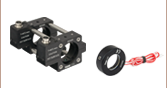
ケーブルHR10CAB1とHR10AD1には6ピンHiroseコネクタが付いています。ケーブルHR10CAB1は長さ3.0 mで、両端にオス型コネクタが付いています。ケーブルHR10AD1は長さ1.8 mで、1端にはHiroseコネクタ、もう一端にははんだ付けせずにワイヤ素線を接続できるブレイクアウトボックスが付いています。.
これらのケーブルは、当社のヒータ温度コントローラTC300Bに対応しており、ブレイクアウトボックスを使用すると抵抗ヒータやサーミスタを独自に組み合わせて接続できます(右図参照)。ケーブルHR10CAB1を使用すると、ビームシャッタのSH05R/MやSH1/MをシャッターコントローラSC10やソレノイドコントローラK-Cube KSC101に接続できます。
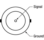
はんだ付けして独自に接続したい場合には、Hiroseコネクタ付きケーブルを任意の長さで切断し、一方はコネクタ付き、もう一方は裸線にしてお使いいただくこともできます。上のワイヤの図は6本の色付きワイヤとコネクターピンとの関係を示しています。この図を参考にすれば、ブレイクアウトボックスが適していない場合でも、ケーブルを切断して様々なカスタム用途に組み込むことができます。 なお、これらのワイヤはケーブル内で交差するため、ピンの識別には絶縁カラーをご利用ください。
HR10AD1のブレイクアウトボックスの各ポートには、それぞれHirose製オス型コネクタの各ピンに対応するピン番号のラベルが付いています(左図参照)。またピン番号のラベルに隣接して空白のラベルが付いており、独自のピン割り当て情報を追記することもできます。 ラベルの記入には、変更時に一般的な消しゴムで消せるように、グラファイト鉛筆の使用をお勧めしています。