 Products Home
FC/APCコリメーターパッケージ、焦点固定型

- Mates with FC/APC Connectors
- Simplifies Collimation of Output from Single Mode Fiber
- Collimated Beam Diameters Ranging from 0.63 mm to 4.05 mm
- Models Aligned at 13 Key Wavelengths from 405 nm to 4.55 µm
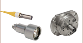
F240APC-A
543 nm, Focal Length: 7.86 mm
Shown with Patch Cable
F220APC-1064
1064 nm, Focal Length: 11.17 mm
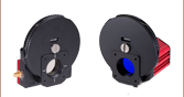
Back
Front
Fixed Focus Collimators Contain
One Factory-Aligned Aspheric Lens


Please Wait
特長
- FC/APCコネクタ付きシングルモードパッチケーブル用ファイバーコリメータ
- 波長範囲405 nm~4.55 µmでアライメント(右表参照)
- コリメートビーム径:波長により0.63 mm~4.05 mm
- 各コリメーターパッケージは工場でアライメント済み
- ファイバ結合型検出システムの簡略化
- 非磁性のステンレススチール製筐体
- ナローキーおよびワイドキーのFC/APCコネクタに対応
- カスタムアライメント波長などの特注も承っております。詳細は当社までご相談ください。
ファイバーコリメーターパッケージはFC/APCコネクタ付きファイバからの光を回折限界性能でコリメートするようにアライメントされています。これらのファイバーコリメータには可動部品がなく、小型で、既存のセットアップにも簡単に統合できます。非球面レンズの有効焦点距離(EFL)は、色収差によって波長に依存します。設計波長は適切なビーム広がり角が得られる波長を示しています(詳細は「広がり角のグラフ」ならびに「計算」のタブをご参照ください)。コリメーターパッケージは、異なる波長とコリメートビーム径でご用意しております。詳細は右表の波長のリンクをクリックしてご覧ください。
非球面レンズは、特定のシングルモードファイバーパッチケーブルに接続したときに、設計波長でコリメートするように工場でアライメントされます。また、非球面レンズの両面には表面反射を最小にするようARコーティングが施されています(「ARコーティングのプロット図」タブをご参照ください)。用途によっては、ARコーティング範囲内の他の波長でも使用できる場合があります。お使いの用途に適しているかどうかについては各コリメータの広がり角グラフ(理論値)をご参照の上、ご確認ください。動作温度範囲は、-40 °C~93 °Cです。また、真空には対応しておりませんのでご注意ください。 異なるアライメント波長や動作温度、真空用途への対応なども特注にて承ります。詳細は当社にご相談ください。
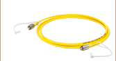
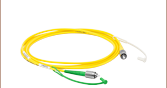
これらのファイバーコリメータはシングルモードファイバーパッチケーブル向けです。性能を十分に発揮させるには、ARコーティング付きシングルモードパッチケーブルと組み合わせてご使用になることをお勧めいたします。これらのケーブルには、透過率の向上およびファイバと自由空間光の接続面における反射損失を低減するため、ファイバの片端に反射防止コーティングが施されています。なお、性能仕様はシングルモードファイバをご使用時のみ保証されます。
ファイバーコリメーターパッケージの取付けには、あおり調整(ピッチ&ヨー)が可能なキネマティックコリメータ取付けアダプタなど、当社のコリメータ取付けアダプタのご使用をお勧めします。Ø12.7 mm(Ø1/2インチ)やØ25.4 mm(Ø1インチ)のネジ無しバージョンのほか、SM05、RMS、SM1の外ネジ付きもご用意しています。M12 x 0.5外ネジ付きコリメーターパッケージは、当社のケージプレートCP1M12/Mに直接取り付けることが可能なので、30 mmケージシステムに組み込むことができます。
中赤外域用コリメータ
アライメント波長が3.45 µmおよび4.55 µmのコリメータには、当社の角度付きで研磨されたフッ化物ファイバーパッチケーブルのご使用をお勧めいたします。これらのコリメータには挿入する際にフッ化物ファイバの先端を保護し、ポインティングの安定性を向上させるために公差の小さいセラミックスリーブが付いています。コリメータは工場で設計波長にアライメントされていますが、その広がり角は広い波長範囲においてそれほど大きくはありません。したがって、ARコーティング範囲内の他の波長でも使用することができる場合があります。各コリメータの広がり角グラフ(理論値)をご覧いただき、用途に適しているかどうかをご確認ください。
その他
当社では、調整機能付きコリメーターパッケージのFiberPortシリーズも取り揃えております。こちらは広い波長範囲に対応する、調整機能付きの小型のファイバーカプラです。コリメートならびにカップリング用のその他のオプションついては「コリメーターガイド」タブをご覧いただくか当社までご相談ください。
| Coating Information | |||||||
|---|---|---|---|---|---|---|---|
| Coating Designation | 405 | Aa | Ba | 1064 | Ca | D | E |
| Coating Range | 395 - 415 nm | 350 - 700 nm or 400 - 600 nm | 600 - 1050 nm or 650 - 1050 nm | 1050 - 1075 nm | 1050 - 1620 nm or 1050 - 1700 nm | 1.8 - 3.0 µm | 3 - 5 µm |
| Reflectance | <0.25% @ 405 nm | Ravg < 0.5% within Coating Range | Ravg< 0.5% within Coating Range | <0.25% @ 1064 nm | Ravg< 0.5% within Coating Range | Ravg < 1.0% within Coating Range | Ravg <1.0% within Coating Range |


| θ | Divergence Angle |
| D | Mode-Field Diameter (MFD) |
| f | Focal Length of Collimator |
広がり角(°) 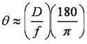 ,
,
Dとfには同じ単位を用います。
広がり角の比較
ファイバからの光がガウス型の強度プロファイルを有する場合、ビームの広がり角は右の計算式で概算することができます。この計算式はシングルモードファイバの場合には良く当てはまりますが、強度プロファイルが非ガウス型になるマルチモードファイバからの出射光に対しては、実際よりも小さい広がり角が計算されます。
下のグラフは、当社の標準のコリメータを設計波長以外の波長で使用したときの広がり角(理論値)を示しています。例えば、ファイバからの700 nmの出射光を直径約1.5 mmのビームにコリメートする必要がある場合、コリメータF240APC-780(F240グラフ内の「-780」の線)を使用することは可能ですが、設計波長である780 nmの波長で使用する場合よりも広がり角は大きくなります。下の各コリメータの説明においても、理論計算による広がり角のグラフとその生データをご提供しています。また、標準ラインナップとは異なる波長用にアライメントされたコリメータをご希望の場合は当社までお問い合わせください。


広がり角の理論近似
下のグラフは、各コリメータの設計波長におけるビーム径の伝搬距離に対する依存性をシミュレーションした結果です。設計ファイバからガウス型強度プロファイルを有する光を入射することを仮定しています。各グラフの下部に設計波長と使用ファイバを記載しています。

Click to Enlarge
波長405 nm、ファイバS405-XP

Click to Enlarge
波長532 nm、ファイバ460HP

Click to Enlarge
波長543 nm、ファイバ460HP


Click to Enlarge
波長780 nm、ファイバ780HP

Click to Enlarge
波長850 nm、ファイバ780HP

Click to Enlarge
波長980 nm、ファイバSM980-5.8-125

Click to Enlarge
波長1064 nm、ファイバSM980-5.8-125

Click to Enlarge
波長1310 nm、ファイバSMF-28-J9

Click to Enlarge
波長1550 nm、ファイバSMF-28-J9

Click to Enlarge
波長2000 nm、ファイバSM2000

Click to Enlarge
波長3.45 µm、ファイバZrF4

Click to Enlarge
波長4.55 µm、ファイバ InF3
広がり角の理論的近似
仕様表に記載されているビームの全広がり角(Divergence)は、ファイバーコリメータに関する理論的な計算値です。ファイバからの光がガウス型の強度プロファイルを有する場合、下記の式でその広がり角の理論的近似値を簡単に求めることができます。この計算式はシングルモードファイバの場合にはよく当てはまりますが、マルチモードファイバの場合はその出射光が非ガウス型の強度プロファイルを有するため、この式では広がり角が実際よりも小さく見積もられてしまいます。
全広がり角(°)は以下の式で求められます。
ここでMFDはモードフィールド径、fはコリメータの焦点距離です。(注:この式ではMFDとfには同じ単位を使わなければなりません)。
例:
コリメータF220FC-A(f ≈ 11.0 mm:「≈」とした理由は設計波長が543 nmのため)を使用して、ファイバ460HP(MFD = 3.5 µm)からの515 nmの光をコリメートする場合、広がり角の近似値は
θ ≈ (0.0035 mm / 11.0 mm) x (180 / pi) = 0.018°となります。
コリメータF220FC-Aとファイバ460HPを使って534 nmのビーム広がり角を測定してみると、その結果は0.018°でした。
出力ビーム径の理論的近似
出力ビーム径は以下の式で近似値が求められます。
ここでλは光の波長、MFDはモードフィールド径、fはコリメータの焦点距離です。(注:この式ではMFDとfには同じ単位を使わなければなりません)。
例:
コリメータF240FC-1550(f = 8.18 mm)とパッチケーブルP1-SMF28E-FC-1(MFD = 10.4 µm)を組み合わせて1550 nmの光を使用した場合、その出力ビーム径は
d ≈ (4)(0.00155 mm)[8.18 mm / (pi · 0.0104 mm)] = 1.55 mmとなります。
ビームウェストまでの最大距離(Maximum Waist Distance)の理論的近似
ビームウェストまでの最大距離、つまりコリメート状態を維持できるレンズからビームウェストまでの最大距離は、以下の式で近似的に得られます。
ここでfはコリメータの焦点距離、λは光の波長、そしてMFDはモードフィールド径です。(注:この式ではMFDとfには同じ単位を使わなければなりません)。
例:
コリメータF220FC-532(f = 10.9 mm)とパッチケーブルP1-460B-FC-1(MFD ≈ 4.0 µm:計算された近似値)を組み合わせて532 nmの光を使用した場合、ビームウェストまでの最大距離の近似値は
zmax ≈ 10.9 mm + [2 · (10.9 mm)2 · 0.000532 mm] / [pi · (0.004 mm)2] = 2526 mmとなります。

Insights:光学実験のベストプラクティス
こちらのページでは下記について説明しています。
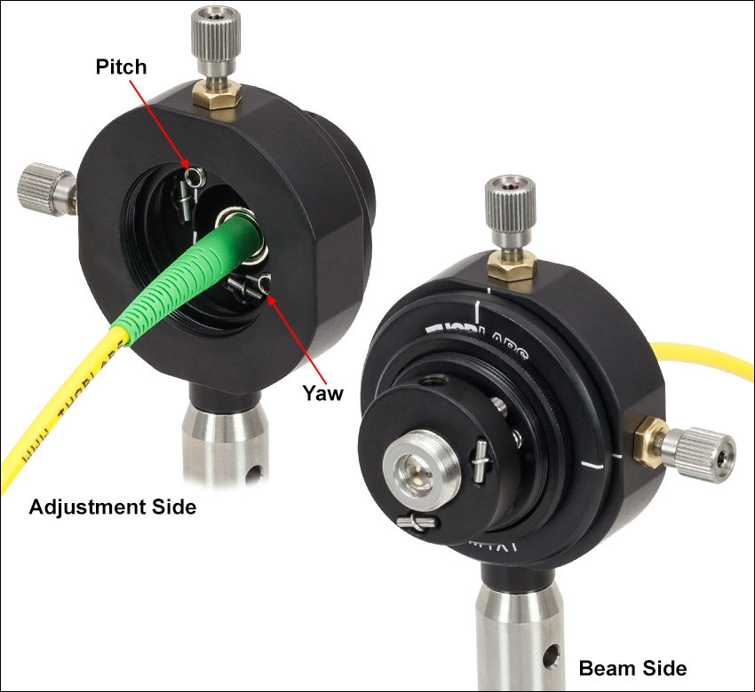
- 2本のファイバ間にコリメートされた自由空間光を生成するためのファイバーコリメータのアライメント方法
- ファイバーコリメータ:アダプタを使って取り付ける場合のヒント
このほかにも実験・実習や機器に関するヒントをまとめて掲載しています。こちらからご覧ください。
2本のファイバから出力された光を自由空間を介して結合するためのファイバーコリメータのアライメント方法
光ファイバのセットアップの間に2つのコリメートレンズを挿入することによって、様々なビームへの操作が可能な自由空間光を得ることができます。1つ目のコリメータは出射側ファイバからの発散光を受光し、それによってコリメートされた自由空間ビームは2つ目のコリメータに向けてほぼ一定の径で伝搬します。2つ目のコリメータは自由空間ビームを受光し、受光側のファイバに結合します。こちらの動画においてペアで使用されているコリメーターパッケージのように、ファイバを直接ファイバーコネクタに接続するように設計されている製品がございます。
出射側のファイバからの光を100%の効率で受光側のファイバに結合できれば理想ですが、実際には常に反射、散乱、吸収、ミスアライメントなどによって損失が生じます。通常、光損失の最も大きな原因となるミスアライメントは、こちらの動画でご紹介しているアライメント法や安定化の方法により最小化することができます。
この動画では、出射側のファイバとしてシングルモードファイバを使用しています。2つ目のコリメータに入射する光パワーと、受光側のファイバから出射される光のパワーを測定しています。受光側のファイバがコア径50 µmのマルチモードファイバの場合、アライメントを行うことで、2つ目のコリメータに入射した光パワーの91%が受光側ファイバからの出射光として測定されました。受光側のファイバがシングルモードファイバの場合、この値は86%になりました。動画では、コリメータの設計の違いと、その違いがコリメート光の特性に及ぼす影響などについてもご説明しています。
そのほかにも実験室でお使いいただけるヒント、工夫や方法などの動画がこちらからご覧いただけます。また、ウェビナーでは、当社の様々な製品に関する理論や実用的な事柄などをご紹介しています。
| Products Featured During Demonstration | ||||
|---|---|---|---|---|
| Fiber-Coupled Laser | Kinematic Mounts | Fiber Adapter Cap (for Power Sensor) | Single Mode Patch Cable (FC/PC) | Fiber Cable Storage Reels |
| Triplet Fiber Optic Collimators | Power Sensor | Power Meter | Hybrid Single Mode Patch Cable | 2" Posts |
| Adapter (Mount-to-Collimator) | SM1 Thread Adapter (for Power Sensor) | Fiber Connector Cleaner | Step-Index Multimode Patch Cable | Ø1/2" Post Holders |
最終更新日:2021年4月1日
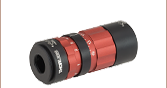
ファイバーコリメータ:アダプタを使って取り付ける場合のヒント

Click to Enlarge
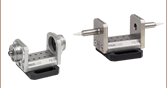
図1:上の図では各コンポーネントをネジで結合しています。ファイバーコネクタのネジを緩めると、意図せずほかの部品同士の接続まで緩めてしまう場合があるため、当社ではほかの2箇所の接続部を接着剤で固定することをお勧めしています。
ファイバーコリメータは、ファイバ出力型光源から光学系に光を入射するときによく使用されます。当社では様々な種類のファイバーコリメーターパッケージをご用意しております。その一部のパッケージはネジの無い滑らかなバレル(トリプレットコリメータなど)になっていますが、ほかにはバレルの先端にミリ規格のネジ(非球面コリメータなど)が付いているものがございます。
通常当社では、どちらのパッケージにも、バレルを2線接触で保持するタイプの、先端がナイロン製の止めネジ(セットスクリュ)が付いたアダプタの使用をお勧めしております。
一方、ファイバーコリメータをマウントにねじ込むことができる、外ネジ付きのアダプタ(AD1109F)もございます。
しかし、このようなアダプタを使用した場合、ネジによる接続が重なってきます(ネジ付きファイバーコネクタ、ネジ付きコリメータ、そしてネジ付きアダプタ)。その結果、ファイバーコネクタを緩めるときに注意しないと、その他のネジによる接続部分まで緩めてしまい、セットアップに原因不明な不安定性が生じる場合があります。
そのため、このような取り付け方をしたい場合には、当社ではネジ付きファイバーコリメータとネジ付きマウントを接着剤で固定することをお勧めしています。
図1では組み立て部品の配列と接着剤を塗布する箇所を示しています。
最終更新日:2019年12月4日
ファイバーコリメーターセレクションガイド
コリメータの種類または画像をクリックすると、各コリメータの詳細がご覧いただけます。
| Type | Description | |
|---|---|---|
| 焦点固定型FC、APC、SMAファイバーコリメータ | 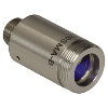 | こちらのファイバーコリメーターパッケージは、FC/PC、FC/APC、またはSMAコネクタ付きファイバからの出射光をコリメートするように、予めアライメントされています。各コリメーターパッケージは、405 nm~4.55 µmの波長で回折限界性能が得られるように工場で調整されています。設計波長以外でコリメータを使用することは可能ですが、色収差が生じるため最適な性能が得られるのは設計波長においてのみです。非球面レンズの実際の焦点距離は、色収差により波長に依存します。 |
| エアスペース型複レンズ、大径ビームコリメータ | 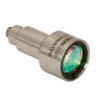 | 大径ビーム(Ø5.3 mm~Ø8.5 mm)用として、FC/PC、FC/APC、SMAコネクタ付きエアスペース型複レンズコリメータをご用意しています。こちらのコリメーターパッケージは、FCやSMAコネクタ付きファイバからの出射光をコリメートし、設計波長で回折限界性能が得られるように工場で予めアライメントされています。 |
| トリプレットレンズコリメータ | 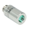 | 高品質なトリプレットコリメーターパッケージは、エアスペース型トリプレットレンズを使用しており、非球面レンズを用いたコリメータよりも優れたビーム品質が得られます。収差の小さいトリプレットを用いることの利点は、M2値として1(ガウシアン)に近い値が得られ、広がり角や波面エラーが小さくなることなどです。 |
| マルチモードファイバ用アクロマティックコリメータ | 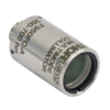 | 高NAアクロマティックコリメータは、メニスカスレンズとアクロマティック複レンズを組み合わせることで、可視~近赤外スペクトル域において球面収差の少ない優れた性能を発揮します。高NAのマルチモードファイバ用に設計されているため、オプトジェネティクスやファイバーフォトメトリの用途に適しています。 |
| 反射型コリメータ |  | 金属コーティング反射型コリメータは、90°軸外放物面(OAP)ミラーをベースにしています。レンズと違い、ミラーは広い波長範囲にわたり焦点距離が変化しません。この特性により、軸外放物面(OAP)ミラーを用いたコリメータは広い波長範囲に対応させるための調整が不要となるため、多色光を用いる用途に適しています。当社の反射型コリメータはシングルモードファイバからの光のコリメートには適していますが、シングルモードファイバへの結合には適していません。これらのコリメータにはUV強化型アルミニウムコーティングと保護膜付き銀コーティングの製品をご用意しており、それらにはFC/PC、FC/APCまたはSMAコネクタが取り付けられています。 |
| コンパクト反射型コリメータ |  | このコンパクトな反射型コリメータには、保護膜付き銀コーティングが施された90°軸外放物面(OAP)ミラーが組み込まれています。OAPミラーの焦点距離は波長に依存しないため、多色光用として適しています。 この固定式の反射型コリメータは、シングルモードファイバやマルチモードファイバからの出射光のコリメート用、およびマルチモードファイバへの光結合用として推奨しています。 これらのコリメータは当社の16 mmケージシステムに直接取り付けられます。 光入射用として、FC/PC、FC/APCまたはSMAコネクタの取り付けられた製品をご用意しています。 |
| 調整機能付き反射型コリメータ | 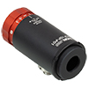 | 調整機能付き反射型コリメータは、保護膜付き銀コーティングが施された90°軸外放物面(OAP)ミラーをベースにしています。ファイバ-OAP間の距離が調整可能であり、またOAPミラーが波長によらず一定の焦点距離を有します。そのため、シングルモードまたはマルチモードファイバからの多色光をコリメートしたり、あるいは逆に多色光をそれらのファイバに結合したりすることができ、その際に最適化のための調整も可能です。これらの調整機能付きコリメータは15 mmの反射焦点距離を有し、FC/PC、FC/APC、またはSMAコネクタ付きの製品をご用意しています。 |
| FiberPort | 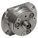 | こちらのコンパクトで極めて安定なFiberPortマイクロポジショナは、FC/PC、FC/APCまたはSMAコネクタ付き光ファイバとの光の入出射用として、安定で使いやすいプラットフォームです。シングルモード、マルチモードまたは偏波保持ファイバと組み合わせて使用することができ、ポスト、ステージ、プラットフォーム、レーザなどに取り付けることができます。組み込まれている非球面またはアクロマティックレンズのARコーティングは5種類から選択でき、また5軸のアライメント調整(3つの移動調整と2つの角度調整)が可能です。コンパクトでアライメントの長期安定性に優れたFiberPortは、ファイバへの光の結合、コリメート、組み込み用途(OEM用途)などに適しています。 |
| 調整可能型ファイバーコリメータ |  | このコリメータは、FC/PC、FC/APCまたはSMAコネクタに接続するよう設計されており、内部にはARコーティング付き非球面レンズが取付けられています。非球面レンズとファイバ先端との距離は、焦点距離の変化を補正したり、波長や対象までの距離に合わせて再コリメートしたりするために調整することができます。 |
| アクロマティックファイバーコリメータ、焦点調整可能 | 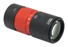 | 焦点調整の可能な当社のアクロマティックファイバーコリメータは、20 mm、40 mmまたは80 mmの有効焦点距離(EFL) を有し、その光学素子のARコーティングは3種類の広帯域ARコーティングから選ぶことができます。また、接続用コネクタの種類としては、FC/PC、FC/APCまたはSMA905をご用意しています。4枚のレンズを使用したエアスペース型設計であるため、非球面レンズのコリメータに比べてビーム品質に優れ(1に近いM2)、波面誤差は小さくなっています。これらのコリメータは自由空間光のファイバへの結合や、ファイバからの出射光のコリメートなどにご使用いただけます。また、距離をとって配置した2つのコリメータを用いて光を結合させると、光が2番目のコリメータに入る前にそのビームを操作することが可能になります。 |
| ズーム機能付きファイバーコリメータ |  | こちらのコリメータは、ビームをコリメートしたまま、6~18 mmの範囲で焦点距離を変えることができます。そのため、コリメートした状態でビームサイズを変更できます。このデバイスは、用途に適した固定のファイバーコリメータを探す手間を省けるという利点に加え、1つで様々な幅広い用途に対応することができます。FC/PC、FC/APCまたはSMA905コネクタが付いており、反射防止コーティングは3種類からお選びいただけます。 |
| シングルモードファイバーピグテール付きコリメータ | 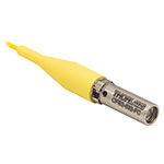 | シングルモードファイバーピグテール付きコリメータは、長さ1メートルのファイバとそれに対して予めアライメントされたARコーティング付き非球面レンズとで構成されており、532 nm、633 nm、780 nm、850 nm、1030 nm、1064 nm、1310 nm、1550 nmの8波長用の製品をご用意しています。コーティング波長域内のどの波長でもコリメートできますが、設計波長からずれると結合損失が増加します。 |
| 偏波保持ファイバーピグテール付きコリメータ | 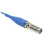 | 偏波保持ファイバーピグテール付きコリメータは、長さ1メートルのファイバとそれに対して予めアライメントされたARコーティング付き非球面レンズとで構成されており、633 nm、780 nm、980 nm、1064 nm、1550 nmの5波長用の製品をご用意しています。波長やコネクタについてはカスタム仕様も対応可能です。筐体の外側にはスロー軸と平行なラインが刻印されています。これは入射光の偏光面をアライメントする際の目安としてお使いいただけます。コーティング波長域内のどの波長でもコリメートできますが、設計波長からずれると結合損失が増加します。 |
| GRINレンズコリメータ | 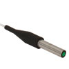 | GRINレンズファイバーコリメータは、630~1550 nmの範囲内の様々な波長に対してアライメントされた製品をご用意しており、FCまたはAPCコネクタ付きもしくはコネクタ無しのタイプからお選びいただけます。この有効径Ø1.8 mmのGRINレンズコリメータは、ファイバへの後方反射光を抑えるためにARコーティングが施されており、標準のシングルモードファイバまたはグレーデッドインデックス(GI)マルチモードファイバに結合されています。 |
| GRINレンズ | 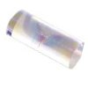 | この屈折率分布型(GRIN)レンズは630 nm、830 nm、1060 nm、1300 nm、または1560 nmの波長用にARコーティングが施されており、光ファイバから出射した光が自由空間の光学系を通過して再度別のファイバに入射するまでの各用途にご利用いただけます。また半導体レーザの出射光のファイバへの結合、ファイバからの出射光のディテクタへの集光、レーザ光のコリメートなどにも適しています。このGRINレンズは当社の ピグテール付きガラスフェルールやGRINレンズ/フェルール用スリーブと組み合わせてお使いいただくこともできます。 |
| Posted Comments: | |
Roberto Hinojosa
(posted 2024-07-11 16:34:08.027) Hello, Our team is interested in buy a couple of focus collimators but we are confused with the NA (numerical aperture) and the MFD. In Calculations you have on Theoretical Approximation of the Divergence Angle:
When the F240FC-1550 collimator (f = 8.18 mm) is used with the P1-SMF28E-FC-1 patch cable (MFD = 10.4 µm) and 1550 nm light, the output beam diameter is
d ≈ (4)(0.00155 mm)[8.18 mm / (pi · 0.0104 mm)] = 1.55 mm.
From here we could have de NA as NA=sin(a)≈tan(a)=d/f, were
the NA must be NA=1.55mm/8.18mm=0.18
But on the information of the P1-SMF28E-FC-1 patch cable you said that NA=0.14. Our question is, we are computed something wrong? Or your data is wrong ? or, we are missing something? Thank you. cdolbashian
(posted 2024-08-14 12:16:22.0) Thank you for reaching out to us with this inquiry. Sometimes there is a bit of confusion when applying NA considerations to SM fiber, since the NA does not equal the divergence angle, specifically for SM fibers, compared to MM fibers. We have a small article regarding this fact here: https://www.thorlabs.com/newgrouppage9.cfm?objectgroup_id=14204. I have contacted you directly in order to discuss this further with you. 施 议焕
(posted 2023-08-02 22:58:15.96) 请问,我们对这个产品有几个问题
1. 这个产品如果反向使用的话是否可以作为一个聚焦透镜使用,用于将空间光聚焦到光纤上?
2. 有这个产品全部波段的增透膜曲线的数据吗?我们希望获得980nm激光对这个产品的透射率
3.或者你们有这个产品未镀膜片的版本吗?希望对2.8 um和0.98 um的激光进行聚焦 cdolbashian
(posted 2023-08-04 11:24:59.0) 1. Can this product be used as a focusing lens if used in reverse to focus spatial light onto an optical fiber?
2. Do you have the data of AR coating curves for all bands of this product? We hope to obtain the transmittance of 980nm laser to this product
3. Or do you have an uncoated version of this product? Want to focus 2.8 um and 0.98 um laser"
1. Indeed this component can take a collimated input and focus the light to a fiber.
2. We have sent you additional, extended, data
3. We have reached out to you to discuss this. user
(posted 2023-04-05 20:19:08.69) Dear Sir/Madam,
We have F230APC-1310 collimators and I want to create free space with these collimators. The distance between collimators is 12.5 cm and light source is BOA1130-P. Unfortunately, I cannot exceed 50% coupling efficiency. For example, My total power is 9.5 mW. I cannot exceed 4.2 mW.
In addition, the back reflection from receiver collimator, is clearly seen near the top of the transmitter collimator's aspheric lens. I got the highest power with this setup. When I try to align back reflection, I get nothing. What is my problem and how can I solve this? cdolbashian
(posted 2023-04-26 09:27:31.0) Thank you for reaching out to us with this inquiry. Before I was able to post this, you and I exchanged some emails, and it seems like the inclusion of appropriate kinematic control assisted you in achieving ~80% coupling. Cristian Tong
(posted 2023-01-04 05:50:07.073) Hello, Can the F260APC-780 collimator be used to couple a free-space beam into the fiber? and, Can this collimator adapted with PM fibers?
Thank you cdolbashian
(posted 2023-01-10 02:27:31.0) Thank you for reaching out to us with this inquiry! These can be used to couple a free space beam into the fiber though since everything is fixed, you may have trouble getting greater than 50% coupling efficiency. While you can use it with a PM fiber, you might not have well-reproducible results with regards to alignment of one of the polarization axes, as we use wide-key adapters on our fiber collimators for ease of use with any FC-style fiber. Arun Jana
(posted 2022-12-10 15:21:47.333) Dear Sir/Madam,
is this output from single-mode polarization maintaining fiber?
looking forward....
Thanks. cdolbashian
(posted 2022-12-15 01:48:28.0) Thank you for contacting us with this inquiry. These collimators are housings for lenses which are nominally isotropic materials. As such we would assume there would be no change of the polarization state while passing through. Emirhan Tosun
(posted 2022-11-30 22:03:42.45) Dear Sir/Madam
I have products with code F280APC-C , AC254-030-C-ML. Can I learn the damage threshold values?
Thanks in advance. Best rigards.
Emirhan Tosun jgreschler
(posted 2022-12-06 01:27:59.0) Thank you for reaching out to Thorlabs. Unfortunately we do not currently have a damage threshold spec for that item. user
(posted 2022-06-24 21:31:54.617) I would like to use F240APC-C with POLARIS-K05T6, which adapter should I use?
Thanks in advance, jdelia
(posted 2022-06-30 04:31:21.0) Thank you for contacting Thorlabs. I have contacted you directly regarding your application. Jan Fait
(posted 2021-11-04 04:27:03.92) Please, is the collimator F240APC-532 suitable for coupling elliptic beam (532 nm, 1.5 mm x 3.5 mm) to a single mode optical fiber (e.g. P3-460B-FC)? Or is it better to use collimator with short focal length (F110APC-532) to have very small focal spot?
Thanks in advance, Jan YLohia
(posted 2021-12-23 11:24:10.0) The shorter focal length will, by definition, produce a smaller beam size for a gaussian beam when focussed. The main consideration you should be wary of is your NA match with the fiber. You will ideally want your NA_fiber > NA_lens+laser, where the NA of the laser would be D/(2*f), where D is the incoming beam diameter, and f is the focal length.
Depending on your fiber and the beam diameter (semi major axis of elliptical beam) at the lens surface, you should pick the appropriate lens with the smallest focal length to satisfy your coupling needs. Ideally you would want to go for a fiberport coupling solution as it has multiple degrees of freedom, which are necessary to get optimal coupling to an SM fiber, due to their core sizes being on the same order as the beam waist. Phani Kumar
(posted 2021-09-25 20:51:15.293) Kindly clarify if the Thorlabs F260APCA collimator is compatible with Polarization-Maintaining FC/APC Fiber Optic Patch Cables. YLohia
(posted 2021-10-11 02:51:07.0) Thank you for contacting Thorlabs. Yes, our FC/APC fiber collimators, such as the F260APC-A, are compatible with FC/APC fiber patch cables (including PM APC cables). wu chao
(posted 2021-05-17 03:18:06.38) 请问准直器的损伤阈值是多少 YLohia
(posted 2021-05-19 01:34:39.0) Thank you for contacting Thorlabs. An applications engineer from our team in China (techsupport-cn@thorlabs.com) will reach out to you directly. user
(posted 2020-06-18 16:43:08.663) To whomever it may concern,
I am concerned about the beam profile from the collimator. Is there information on the truncation of the beam at the lens? nbayconich
(posted 2020-06-23 02:26:04.0) Thank you for your feedback, our fixed focus collimators should not truncate your beam as long as the numerical aperture of the fiber is less than the NA of the collimation package. It would be best to have more information about your fiber first before suggesting a particular collimation package. I will reach out to you directly to discuss your application. Filippo Piffaretti
(posted 2020-04-22 19:00:34.933) Dear Thorlabs,
In my system (915nm) I do need a fixed APC collimator but with a lens with a focal lens of 2mm as one of your adjustable collimator.
In alternative, can you provide ans adjustable collimator with Focal lens of 2mm and a APC connector! With the current PC I loose more than 30% of the laser beam.
Thanks in advance,
Filippo YLohia
(posted 2020-04-24 08:37:57.0) Hello Filippo, thank you for contacting Thorlabs. We offer the PAF2-2B FiberPort collimator with 2 mm focal length, which can be used with FC/APC connectors. This unit will allow 4.4 degrees worth of adjustment on the lens. Please note that after correcting for the 4 degrees for the tilt from APC, you will only have 0.1 mm worth of travel. I have posted your request for APC fixed collimator options for shorter focal lengths on our internal engineering forum for further consideration as a future product. Leonardo de Melo
(posted 2020-03-18 10:13:06.763) I see the transmission listed for the C20APC-C collimator listed, but not for the F280APC-C or the TC18APC-1064. Can you please provide those? YLohia
(posted 2020-03-18 10:40:28.0) Thank you for contacting Thorlabs. The F280APC-C uses the 354280-C lens and its transmission can be found here : https://www.thorlabs.com/images/popupimages/354280_plt.gif. I will reach out to you directly with information regarding the TC18APC-1064. Vasliliy Voropaev
(posted 2019-12-12 12:24:51.21) Hello, could you please write the material and thickness of the lens in the collimator F240APC-1550? We want to calculate ultrashort pulse broadening in this collimator. YLohia
(posted 2019-12-12 01:11:18.0) Hello, thank you for contacting Thorlabs. The material and thickness of the lens used in the F240APC-1550 can be found here : https://www.thorlabs.com/_sd.cfm?fileName=15681-E0W.pdf&partNumber=A240-C Pierre G
(posted 2019-09-26 11:56:16.037) Hello,
What is the material and/or index@532nm for the lense of the F110APC-532 collimator ?
Thanks. YLohia
(posted 2019-09-26 12:10:54.0) Hello, thank you for contacting Thorlabs. A slightly modified version of our 355110-A lens is used in this collimator and its specs can be found here (https://www.thorlabs.com/_sd.cfm?fileName=TTN021132-E0W.pdf&partNumber=355110-A). The lens is made of D-ZLAF52LA. We also share the Zemax file for the F110APC-532 on its product page, which can be used to set up ray simulations. Jerry Liu
(posted 2019-08-28 18:58:34.56) Dear Madam or Sir, Why is the fiber connection part of the collimator is made slightly tilted? what's the purpose of it? And will it affect the transmission of different linear polarization? YLohia
(posted 2019-08-28 12:44:49.0) Hello, thank you for contacting Thorlabs. This connector has the same basic design as the flat FC/PC connector, but is tilted at 4 degrees such that it can accept an FC/APC fiber end which is polished at an 8 degree angle. This “Angled Physical Contact” (APC) interface prevents light reflected at the fiber-fiber junction from traveling back up the fiber. FC/APC connectors only mate properly with other FC/APC connectors. Mating FC/APC with any other connector results in high insertion loss. These connectors minimize back reflections but have a higher insertion loss than their FC/PC counterparts. Using an APC connectorized fiber with an APC collimator will not cause any additional polarization affects. v.t.tenner
(posted 2018-08-31 10:30:31.257) I measured the divergence and beam profile of a F240APC-532, using 520nm light and a P3-488PM-FC-2 and a WinCamD beam profiler. I find a 5x higher divergence than the specs, and a focus in the beam. I repeated this measurements with a non-pm fiber for 633nm and find comparable results. How large are all the tolerances and how likely it is that a different fiber coupler will give values that are so much out of spec? nbayconich
(posted 2018-09-06 04:59:36.0) Thank you for contacting Thorlabs. My apologies that this collimator did not meet our specifications, this is not typical of these collimators. We can of course take back this unit and replace it. I will contact you directly with more information. danielpwhite1993.dw
(posted 2018-06-25 15:07:46.49) Can I use the same F240APC-532 to collimate 405nm and 532nm from SM400 fibre? YLohia
(posted 2018-06-25 10:10:32.0) You could use the same collimator, however, the level of collimation and beam diameters for the two wavelengths will be different as can be seen here: https://www.thorlabs.com/images/TabImages/Divergence_F240-532_780.gif. For a truly achromatic performance, we recommend using reflective collimators that can be found on this page: https://www.thorlabs.com/newgrouppage9.cfm?objectgroup_id=4093. jchg2758
(posted 2017-10-16 18:44:22.977) Can I used this receptacle collimator to PM fiber? It is denoted as for single mode fiber but I wanna know how it is designed for single mode (only?). tfrisch
(posted 2017-10-17 04:06:24.0) Hello, thank you for contacting Thorlabs. You can use these collimators in reverse to couble light into PM fiber as it is also single mode. The input polarization will need to be linear and aligned to the PM axis of the fiber. I will contact you directly to discuss this. andreas.rohrbacher
(posted 2017-02-02 03:28:02.83) Hi. What are the temperature specs (operating and storage) for the F240APC-1064? Could the part be temp-cycled +-30 °C from ambient temperature (25°C) without damage to i.e. the lens? tcampbell
(posted 2017-02-06 12:17:50.0) Response from Tim at Thorlabs: thank you for your feedback. The operating temperature range for these collimators is -40 °C to 93 °C. Yes, the collimators can operate in the range of 25 +/- 30 °C. jeremy.saucourt
(posted 2016-05-26 11:24:35.43) Hi. I have several F220APC-1064 collimators placed on kinematic mounts. I use one to collimate the output of a PM980-XP fiber. Then, I use a second one to inject this collimated beam in another PM980-XP fiber.
Before the second collimator, I measure the beam power to be 12 mW (generated by a 1064 nm laser diode). After it, without connecting the fiber to be injected, I measure a 11.8 mW power meaning that alignment is correct. After inserting a 1m welding-free PM980-XP cable and adjusting kinematic knobs for maximal injection, I can only measure up to 4.1 mW, meaning that a maximum of 35 percents of the energy is injected in the fiber. The two collimators are separated by about 5 centimeters.
Any idea on why I cannot inject up to about 90% of the energy on the fiber ? besembeson
(posted 2016-05-26 03:47:04.0) Response from Bweh at Thorlabs USA: The coarse alignment you did helps to center the collimators roughly. After the fiber is inserted, you need to use the kinematic adjustments (hopefully you have at least one) of the mount (s) that hold the collimators to optimize your coupling efficiency. Remember you are creating a spot of under 10um to couple to the fiber so any small misalignment is critical. mesmail
(posted 2015-03-04 08:30:35.033) Hi. I have bought two F280APC-1550 collimators with two P3-SMF28EAR-2 patch cables. I did FSO setup (50 cm distance) with very good alignment and transmitted 30mW using one collimator. When the path cable is not connected to the receiver collimator, I can see the received beam from the collimator output using a viewing card which means the allignment is good. However, when I connected the patch fiber to the receiver collimator, I get very low (in nW) measured using a power meter. Is this because due to the separation distance? any suggestions? jlow
(posted 2015-03-24 11:34:50.0) Response from Jeremy at Thorlabs: It seems that the 2nd collimator is slightly misaligned. It should be placed on a kinematic mount to optimize the alignment. I will contact you directly to discuss more about this. rolland
(posted 2014-12-01 18:22:58.51) Dear Sir or Madam,
I am interested in the collimator F280APC-B to be used with a ~2 mW SLED output at 670 to 680 nm. For our application, the collimator would be placed in a moderate vacuum, of the order of 10^{-6} mbar.
Is the collimator vacuum compatible in this condition ?
Cheers,
L. Rolland jlow
(posted 2014-12-11 01:33:23.0) Response from Jeremy at Thorlabs: These collimators are not vacuum compatible. We can possibly make a custom version. I will contact you directly too discuss about this. clesch
(posted 2014-06-28 16:24:59.027) Dear Madam or Sir,
I'd like to know if one can cause any harm by connecting one of your SM/PC fibers to one of the "Fixed Focus Collimation Packages: FC/APC Connectors" (e.g. F260APC-B) or - vice versa - connecting a SM/APC fiber to a collimation package of FC/PC (e.g. F240FC-B) standard.
Thanks for your information in advance jlow
(posted 2014-08-05 02:33:01.0) Response from Jeremy at Thorlabs: Mismatching the connector type will cause the beam to hit the lens at an angle and distort the output beam. ako.chijioke
(posted 2013-04-22 18:49:05.82) which is recommended for 633nm, f240APC-A or f240APC-B? The latter is aligned at 633 nm but has AR coating that starts at 650 nm. Thanks tcohen
(posted 2013-04-25 16:32:00.0) Response from Tim at Thorlabs: For your 633nm source, it would be preferable to use the F240APC-B for the best collimation performance. The performance of the coating will still be suitable at this wavelength. I will contact you to continue this discussion. koreancarsg
(posted 2013-03-20 12:44:16.377) am looking for a collimator for Fiber coupled superluminescent diode, 1mW @ 680nm. However found closes available is 633nm. Need advice which collimator is suitable? tcohen
(posted 2013-03-21 16:14:00.0) Response from Tim at Thorlabs: We can custom align these collimators to a desired center wavelength. However, as this has a refractive (aspheric) optic it will have chromatic focal shift over the bandwidth of your superluminescent diode and will therefore have poorer collimation quality as you deviate from your center wavelength. Depending on your performance requirements, this may be acceptable. Alternatively, you could look to use a reflective collimator. I will contact you to discuss your setup further. marshabr
(posted 2012-11-29 11:01:09.31) I purchased 4 of the F240APC-1550 collimators. They appear to be focused incorrectly. The far field spot (8 meters) can be reduced in size by about 1/2 if I loosen the nut and pull the fiber away from the lens. The coupling between two collimators or from one collimator to itself via a mirror can be improved by 2x or more by adjusting the fiber position. I tried several different FC/APC connectors from different manufacturers, with similar results.
Is this a known problem with these collimators?
How do you determine the focus point when assembling these collimators? jlow
(posted 2012-08-09 16:02:00.0) Response from Jeremy at Thorlabs: Thank you for your feedback. I have forwarded this to our engineering group to look into. One possible drawback with the S1TM12 is that there's no hard stop for the collimator to push against and therefore might not be suitable in the long run. shaun.johnstone
(posted 2012-08-08 01:21:25.0) Instead of suggesting the AD12F adapter for the F240APC-780 product, I would suggest using the S1TM12 adapter.
This way your fiber collimator is held nicely by the thread on the end of itself, and not by a grub screw (which is not a repeatable mounting scheme). |
| Item # | Alignment Wavelengtha | Lens AR Coating | Waist Diameterb | Waist Distancec | Full Angle Divergenced | Theoretical Divergence | NA | Focal Lengthe | Housing Outer Diameterf | External Threadingf |
|---|---|---|---|---|---|---|---|---|---|---|
| F671APC-405 | 405 nm | 395 - 415 nm Ravg < 0.25% | 0.63 mm | 3.56 mm | 0.05° +0.01 / -0.00° | Raw Data | 0.60 | 4.02 mm | 11 mm | M11 x 0.5 |
| Item # | Alignment Wavelengtha | Lens AR Coating | Waist Diameterb | Waist Distancec | Full-Angle Divergenced | Theoretical Divergence | NA | Focal Lengthe | Housing Outer Diameter | External Threading |
|---|---|---|---|---|---|---|---|---|---|---|
| F110APC-532 | 532 nm | 350 - 700 nm Ravg < 0.5% | 1.14 mm | 5.85 mm | 0.03 +0.01 / -0.00° |  Raw Data | 0.38 | 6.09 mm | 11 mmf | M11 x 0.5f |
| F240APC-532 | 532 nm | 350 - 700 nm Ravg < 0.5% | 1.48 mm | 6.96 mm | 0.03 +0.01 / -0.00° |  Raw Data | 0.51 | 7.86 mm | 12 mmg | M12 x 0.5g |
| F220APC-532 | 532 nm | 350 - 700 nm Ravg < 0.5% | 2.1 mm | 10.72 mm | 0.02 +0.01 / -0.00° |  Raw Data | 0.25 | 10.90 mm | 11 mmf | M11 x 0.5f |
| Item # | Alignment Wavelengtha | Lens AR Coating | Waist Diameterb | Waist Distancec | Full-Angle Divergenced | Theoretical Divergence | NA | Focal Lengthe | Housing Outer Diameter | External Threading |
|---|---|---|---|---|---|---|---|---|---|---|
| F230APC-A | 543 nm | 350 - 700 nm Ravg < 0.5% | 0.83 mm | 4.02 mm | 0.05 +0.01 / -0.00° |  Raw Data | 0.57 | 4.34 mm | 11 mmf | M11 x 0.5f |
| F240APC-A | 543 nm | 350 - 700 nm Ravg < 0.5% | 1.5 mm | 6.97 mm | 0.027° |  Raw Data | 0.51 | 7.86 mm | 12 mmg | M12 x 0.5g |
| F220APC-A | 543 nm | 350 - 700 nm Ravg < 0.5% | 2.06 mm | 10.74 mm | 0.019 +0.010 / -0.000° |  Raw Data | 0.25 | 10.92 mm | 11 mmf | M11 x 0.5f |
| F260APC-A | 543 nm | 400 - 600 nm Ravg < 0.5% | 2.8 mm | 14.85 mm | 0.014° |  Raw Data | 0.17 | 15.01 mm | 11 mmf | M11 x 0.5f |
| F280APC-A | 543 nm | 400 - 600 nm Ravg < 0.5% | 3.3 mm | 17.40 mm | 0.012° |  Raw Data | 0.15 | 18.07 mm | 11 mmf | M11 x 0.5f |
| Item # | Alignment Wavelengtha | Lens AR Coating | Waist Diameterb | Waist Distancec | Full-Angle Divergence | Theoretical Divergence | NA | Focal Lengthd | Housing Outer Diameter | External Threading |
|---|---|---|---|---|---|---|---|---|---|---|
| F230APC-633 | 633 nm | 350 - 700 nm Ravg < 0.5% | 0.84 mm | 4.07 mm | 0.055 +0.01 / -0.00°f |  Raw Data | 0.56 | 4.46 mm | 11 mmh | M11 x 0.5h |
| F110APC-633 | 633 nm | 350 - 700 nm Ravg < 0.5% | 1.16 mm | 5.93 mm | 0.04 +0.01 / -0.00°g | Raw Data | 0.38 | 6.17 mm | 11 mmh | M11 x 0.5h |
| F240APC-B | 633 nm | 650 - 1050 nm Ravg < 0.5%e | 1.5 mm | 6.96 mm | 0.031°g | Raw Data | 0.50 | 7.93 mm | 12 mmi | M12 x 0.5i |
| F220APC-633 | 633 nm | 350 - 700 nm Ravg < 0.5% | 2.06 mm | 10.83 mm | 0.022 +0.01 / -0.00°f |  Raw Data | 0.25 | 11.00 mm | 11 mmh | M11 x 0.5h |
| F260APC-B | 633 nm | 600 - 1050 nm Ravg < 0.5% | 2.8 mm | 14.87 mm | 0.016°g |  Raw Data | 0.16 | 15.15 mm | 11 mmh | M11 x 0.5h |
| F280APC-B | 633 nm | 600 - 1050 nm Ravg < 0.5% | 3.4 mm | 17.52 mm | 0.015°g |  Raw Data | 0.15 | 18.24 mm | 11 mmh | M11 x 0.5h |
| Item # | Alignment Wavelengtha | Lens AR Coating | Waist Diameterb | Waist Distancec | Full-Angle Divergence | Theoretical Divergence | NA | Focal Lengthd | Housing Outer Diameter | External Threading |
|---|---|---|---|---|---|---|---|---|---|---|
| F230APC-780 | 780 nm | 650 - 1050 nm Ravg < 0.5% | 0.98 mm | 4.12 mm | 0.06 +0.01 / -0.00°e |  Raw Data | 0.55 | 4.51 mm | 11 mmg | M11 x 0.5g |
| F110APC-780 | 780 nm | 650 - 1050 nm Ravg < 0.5% | 1.36 mm | 6.00 mm | 0.04 +0.01 / -0.00°f |  Raw Data | 0.37 | 6.24 mm | 11 mmg | M11 x 0.5g |
| F240APC-780 | 780 nm | 650 - 1050 nm Ravg < 0.5% | 1.5 mm | 7.09 mm | 0.036°f |  Raw Data | 0.50 | 8.00 mm | 12 mmh | M12 x 0.5h |
| F220APC-780 | 780 nm | 650 - 1050 nm Ravg < 0.5% | 2.1 mm | 10.91 mm | 0.026°f |  Raw Data | 0.26 | 11.07 mm | 11 mmg | M11 x 0.5g |
| F260APC-780 | 780 nm | 650 - 1050 nm Ravg < 0.5% | 3.33 mm | 15.11 mm | 0.02 +0.01 / -0.00°e |  Raw Data | 0.16 | 15.29 mm | 11 mmg | M11 x 0.5g |
| F280APC-780 | 780 nm | 650 - 1050 nm Ravg < 0.5% | 4.00 mm | 17.68 mm | 0.01 +0.01 / -0.00°e |  Raw Data | 0.15 | 18.40 mm | 11 mmg | M11 x 0.5g |
| Item # | Alignment Wavelengtha | Lens AR Coating | Waist Diameterb | Waist Distancec | Full-Angle Divergence | Theoretical Divergence | NA | Focal Lengthd | Housing Outer Diameter | External Threading |
|---|---|---|---|---|---|---|---|---|---|---|
| F230APC-850 | 850 nm | 650 - 1050 nm Ravg < 0.5% | 0.98 mm | 4.13 mm | 0.06 +0.01 / -0.00°e |  Raw Data | 0.49 | 4.53 mm | 11 mmg | M11 x 0.5g |
| F110APC-850 | 850 nm | 650 - 1050 nm Ravg < 0.5% | 1.36 mm | 6.02 mm | 0.05 +0.01 / -0.00°f |  Raw Data | 0.37 | 6.26 mm | 11 mmg | M11 x 0.5g |
| F240FAPC-850 | 850 nm | 650 - 1050 nm Ravg < 0.5% | 1.74 mm | 7.11 mm | 0.04 +0.01 / -0.00°e |  Raw Data | 0.50 | 8.02 mm | 12 mmh | M12 x 0.5h |
| F220APC-850 | 850 nm | 650 - 1050 nm Ravg < 0.5% | 2.41 mm | 10.94 mm | 0.03 +0.01 / -0.00°e |  Raw Data | 0.25 | 11.12 mm | 11 mmg | M11 x 0.5g |
| F260APC-850 | 850 nm | 650 - 1050 nm Ravg < 0.5% | 3.32 mm | 15.15 mm | 0.02 +0.01 / -0.00°e |  Raw Data | 0.16 | 15.33 mm | 11 mmg | M11 x 0.5g |
| F280APC-850 | 850 nm | 650 - 1050 nm Ravg < 0.5% | 3.99 mm | 17.73 mm | 0.02 +0.01 / -0.00°e |  Raw Data | 0.15 | 18.45 mm | 11 mmg | M11 x 0.5g |
| Item # | Alignment Wavelengtha | Lens AR Coating | Waist Diameterb | Waist Distancec | Full-Angle Divergence | Theoretical Divergence | NA | Focal Lengthd | Housing Outer Diameter | External Threading |
|---|---|---|---|---|---|---|---|---|---|---|
| F230APC-980 | 980 nm | 650 - 1050 nm Ravg < 0.5% | 0.98 mm | 4.16 mm | 0.073 +0.01 / -0.00°e |  Raw Data | 0.49 | 4.55 mm | 11 mmg | M11 x 0.5g |
| F110APC-980 | 980 nm | 650 - 1050 nm Ravg < 0.5% | 1.35 mm | 6.05 mm | 0.05 +0.01 / -0.00°f |  Raw Data | 0.37 | 6.29 mm | 11 mmg | M11 x 0.5g |
| F240APC-980 | 980 nm | 600 - 1050 nm Ravg < 0.5% | 1.7 mm | 7.15 mm | 0.04 +0.01 / -0.00°e |  Raw Data | 0.50 | 8.06 mm | 12 mmh | M12 x 0.5h |
| F220APC-980 | 980 nm | 600 - 1050 nm Ravg < 0.5% | 2.4 mm | 10.99 mm | 0.03 +0.01 / -0.00°e |  Raw Data | 0.25 | 11.16 mm | 11 mmg | M11 x 0.5g |
| F260APC-980 | 980 nm | 650 - 1050 nm Ravg < 0.5% | 3.31 mm | 15.22 mm | 0.022 +0.01 / -0.00°e |  Raw Data | 0.16 | 15.39 mm | 11 mmg | M11 x 0.5g |
| F280APC-980 | 980 nm | 600 - 1050 nm Ravg < 0.5% | 4.0 mm | 17.81 mm | 0.02 +0.01 / -0.00°e |  Raw Data | 0.15 | 18.53 mm | 11 mmg | M11 x 0.5g |
| Item # | Alignment Wavelengtha | Lens AR Coating | Waist Diameterb | Waist Distancec | Full-Angle Divergence | Theoretical Divergence | NA | Focal Lengthd | External Threading | Housing Outer Diameter |
|---|---|---|---|---|---|---|---|---|---|---|
| F230APC-1064 | 1064 nm | 650 - 1050 nm Ravg < 0.5% | 1.00 mm | 4.17 mm | 0.08 +0.01 / -0.00°e |  Raw Data | 0.55 | 4.56 mm | M11 x 0.5g | 11 mmg |
| F110APC-1064 | 1064 nm | 1050 - 1700 nm Ravg < 0.5% | 1.38 mm | 6.07 mm | 0.06 +0.01 / -0.00°f |  Raw Data | 0.37 | 6.31 mm | M11 x 0.5g | 11 mmg |
| F240APC-1064 | 1064 nm | 650 - 1050 nm Ravg < 0.5% | 1.76 mm | 7.16 mm | 0.04 +0.01 / -0.00°e |  Raw Data | 0.50 | 8.07 mm | M12 x 0.5h | 12 mmh |
| F220APC-1064 | 1064 nm | 1050 - 1075 nm Ravg < 0.25% | 2.4 mm | 11.02 mm | 0.032°e |  Raw Data | 0.25 | 11.17 mm | M11 x 0.5g | 11 mmg |
| F260APC-1064 | 1064 nm | 650 - 1050 nm Ravg < 0.5% | 3.37 mm | 15.25 mm | 0.02 +0.01 / -0.00°e |  Raw Data | 0.16 | 15.43 mm | M11 x 0.5g | 11 mmg |
| F280APC-1064 | 1064 nm | 650 - 1050 nm Ravg < 0.5% | 4.05 mm | 17.86 mm | 0.02 +0.01 / -0.00°e |  Raw Data | 0.15 | 18.60 mm | M11 x 0.5g | 11 mmg |
| Item # | Alignment Wavelengtha | Lens AR Coating | Waist Diameterb | Waist Distancec | Full-Angle Divergence | Theoretical Divergence | NA | Focal Lengthd | Housing Outer Diameter | External Threading |
|---|---|---|---|---|---|---|---|---|---|---|
| F230APC-1310 | 1310 nm | 1050 - 1620 nm Ravg < 0.5% | 0.83 mm | 4.20 mm | 0.115 +0.01 / -0.00°e |  Raw Data | 0.54 | 4.59 mm | 11 mmg | M11 x 0.5g |
| F110APC-1310 | 1310 nm | 1050 - 1700 nm Ravg < 0.5% | 1.15 mm | 6.10 mm | 0.08 +0.01 / -0.00°f |  Raw Data | 0.37 | 6.35 mm | 11 mmg | M11 x 0.5g |
| F240APC-C | 1310 nm | 1050 - 1620 nm Ravg < 0.5% | 1.5 mm | 7.21 mm | 0.065°e |  Raw Data | 0.49 | 8.13 mm | 12 mmh | M12 x 0.5h |
| F220APC-1310 | 1310 nm | 1050 - 1620 nm Ravg < 0.5% | 2.04 mm | 11.08 mm | 0.047 +0.01 / -0.00°f |  Raw Data | 0.25 | 11.26 mm | 11 mmg | M11 x 0.5g |
| F260APC-C | 1310 nm | 1050 - 1620 nm Ravg < 0.5% | 2.8 mm | 15.35 mm | 0.034°e |  Raw Data | 0.16 | 15.52 mm | 11 mmg | M11 x 0.5g |
| F280APC-C | 1310 nm | 1050 - 1620 nm Ravg < 0.5% | 3.4 mm | 17.96 mm | 0.028°e |  Raw Data | 0.15 | 18.67 mm | 11 mmg | M11 x 0.5g |
| Item # | Alignment Wavelengtha | Lens AR Coating | Waist Diameterb | Waist Distancec | Full-Angle Divergence | Theoretical Divergence | NA | Focal Lengthd | Housing Outer Diameter | External Threading |
|---|---|---|---|---|---|---|---|---|---|---|
| F230APC-1550 | 1550 nm | 1050 - 1620 nm Ravg < 0.5% | 0.87 mm | 4.21 mm | 0.129 +0.01 / -0.00°e |  Raw Data | 0.54 | 4.61 mm | 11 mmg | M11 x 0.5g |
| F110APC-1550 | 1550 nm | 1050 - 1700 nm Ravg < 0.5% | 1.21 mm | 6.13 mm | 0.09 +0.01 / -0.00°f |  Raw Data | 0.37 | 6.37 mm | 11 mmg | M11 x 0.5g |
| F240APC-1550 | 1550 nm | 1050 - 1620 nm Ravg < 0.5% | 1.6 mm | 7.26 mm | 0.073°f |  Raw Data | 0.49 | 8.18 mm | 12 mmh | M12 x 0.5h |
| F220APC-1550 | 1550 nm | 1050 - 1620 nm Ravg < 0.5% | 2.15 mm | 11.15 mm | 0.053 +0.01 / -0.00°e |  Raw Data | 0.24 | 11.32 mm | 11 mmg | M11 x 0.5g |
| F260APC-1550 | 1550 nm | 1050 - 1620 nm Ravg < 0.5% | 3.0 mm | 15.44 mm | 0.038°f |  Raw Data | 0.16 | 15.58 mm | 11 mmg | M11 x 0.5g |
| F280APC-1550 | 1550 nm | 1050 - 1620 nm Ravg < 0.5% | 3.6 mm | 18.07 mm | 0.032°f |  Raw Data | 0.15 | 18.75 mm | 11 mmg | M11 x 0.5g |
| Item # | Alignment Wavelengtha | Lens AR Coating | Waist Diameterb | Waist Distancec | Full-Angle Divergenced | Theoretical Divergence | NA | Focal Lengthe | Housing Outer Diameterf | External Threadingf |
|---|---|---|---|---|---|---|---|---|---|---|
| F028APC-2000 | 2 µm | 1.8 - 3.0 µm Ravg < 1.0% | 1.2 mm | 5.73 mm | 0.13° +0.01 / -0.00° |  Raw Data | 0.56 | 5.91 mm | 11 mm | M11 x 0.5 |
コリメータは工場で設計波長にアライメントされていますが、その広がり角は広い波長範囲においてそれほど大きくはありません。ARコーティング範囲内の他の波長でも使用することができる場合があります。各コリメータの広がり角グラフ(理論値)をご覧いただき、用途に合っているかどうかをご確認ください。
| Item # | Alignment Wavelengtha | Lens AR Coating | Waist Diameterb | Waist Distancec | Full-Angle Divergenced | Theoretical Divergence | NA | Focal Lengthe | Housing Outer Diameterf | External Threadingf |
|---|---|---|---|---|---|---|---|---|---|---|
| F028APC-3450 | 3.45 µm | 3 - 5 µm Ravg < 1.0% | 2.01 mm | 5.77 mm | 0.125 +0.01 / -0.00° |  Raw Data | 0.56 | 5.94 mm | 11 mm | M11 x 0.5 |
コリメータは工場で設計波長にアライメントされていますが、その広がり角は広い波長範囲においてそれほど大きくはありません。ARコーティング範囲内の他 の波長でも使用することができる場合があります。各コリメータの広がり角グラフ(理論値)をご覧いただき、用途に合っているかどうかをご確認ください。
| Item # | Alignment Wavelengtha | Lens AR Coating | Waist Diameterb | Waist Distancec | Full-Angle Divergenced | Theoretical Divergence | NA | Focal Lengthe | Housing Outer Diameterf | External Threadingf |
|---|---|---|---|---|---|---|---|---|---|---|
| F028APC-4950 | 4.55 µm | 3 - 5 µm Ravg < 1.0% | 2.16 mm | 5.79 mm | 0.15 +0.05 / -0° |  Raw Data | 0.56 | 5.97 mm | 11 mm | M11 x 0.5 |