 Products Home / 電動ステージ / 電動直線移動ステージ(リニアステージ) / Motorized 12 mm (0.47") Linear Translation Stages / ORIC® 12 mm Linear Translation Stage with Piezoelectric Inertia Drive
ORIC® 12 mm Linear Translation Stage with Piezoelectric Inertia Drive
- 12 mm Linear Stages with Open- or Closed-Loop Positioning
- 1 kg Horizontal Load Capacity
- Stackable Design for Compact 1-, 2-, or 3-Axis Setups
U.S. Patent 11,606,045
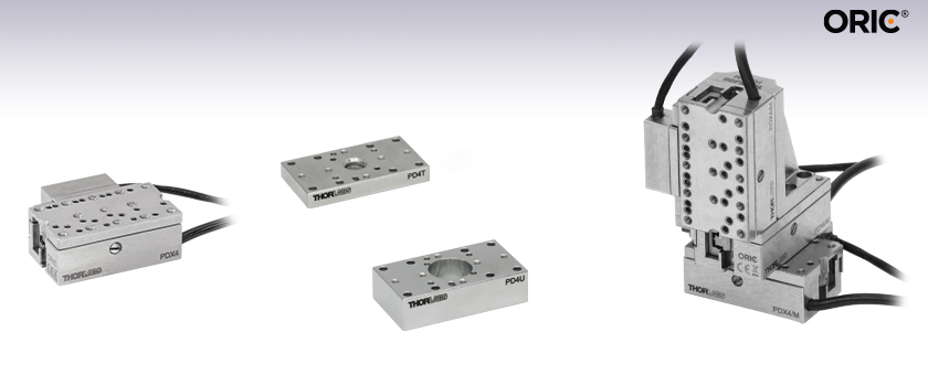
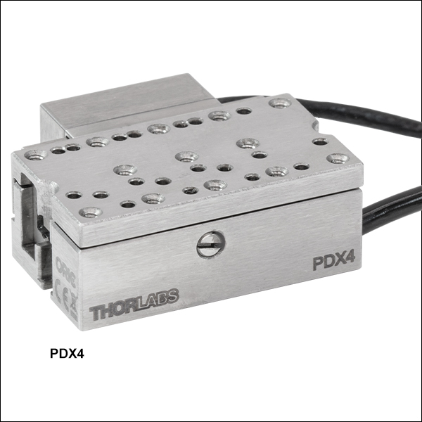
PDX4
Piezo Inertia Stage
with Optical Encoder
Application Idea
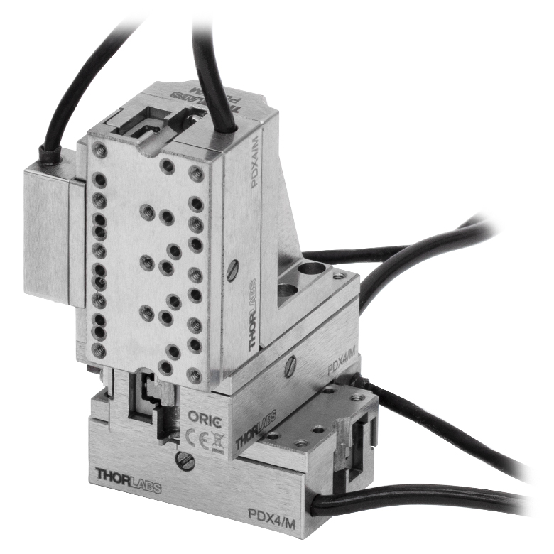
Three PDX4/M Stages in an XYZ Configuration
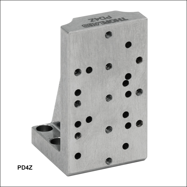
Using a PD4Z/M Right Angle Bracket
PD4U(/M)
#8 (M4) Counterbored
Adapter Plate
PD4T(/M)
8-32 (M4 x 0.7) Threaded
Adapter Plate


Please Wait
| ORIC® Piezo Inertia Stage Selection Guide |
|---|
| 4.5 mm Vertical Translation Stage |
| 5 mm Linear Translation Stages |
| 12 mm Linear Translation Stages |
| 20 mm Linear Translation Stages |
| 50 mm Linear Translation Stage |
| Rotation Stages |
| Vacuum-Compatible Stages |
| Quick Links |
|---|
| Linear Stage with Optical Encoder |
| Adapters |
| Controllers |

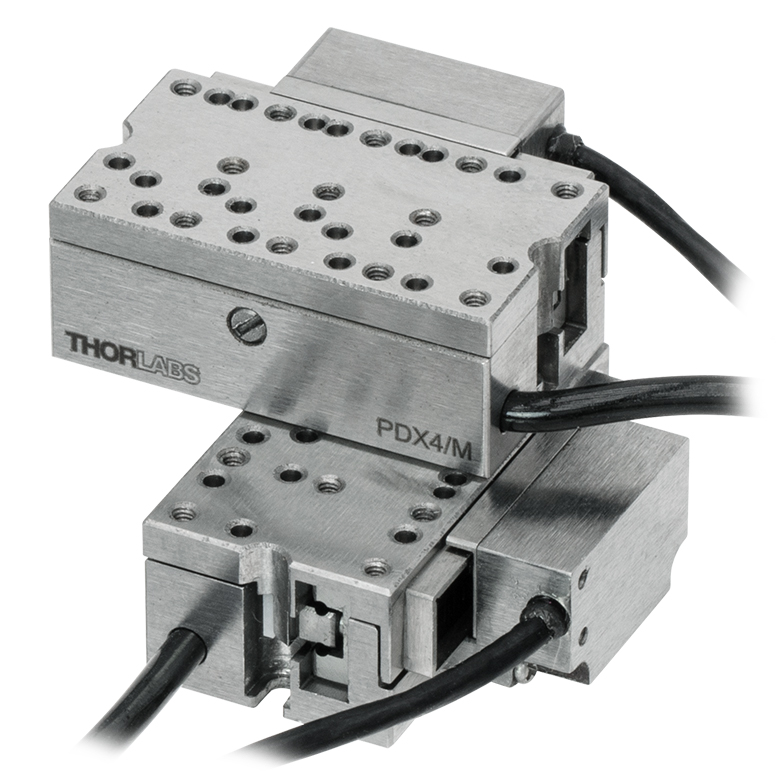
Click to Enlarge
Figure 1.1 Two PDX4(/M) translation stages can be mounted orthogonally to create an XY configuration.
Features
- Compact Stainless Steel Stages with Piezo Inertia Drives
- Ideal for OEMs and Set-and-Hold Applications that Require Relative Positioning with High Resolution
- Top Plate Adapters Provide Alternative Mounting Hole Patterns
- Mounting Adapter Provides Flat Surface for Mounting the Stage
- Right-Angle Bracket Adapter Allows Vertical Mounting and XYZ Configurations
- Requires a Piezo Inertia Stage Controller (Sold Separately Below)
Thorlabs' PDX4(/M) ORIC® Piezoelectric Inertia Drive Stage (U.S. Patent 11,606,045) provides fast and stable piezo-controlled linear motion in a compact package with no backlash. This stage has a horizontal load capacity of 1 kg (2.20 lbs). The piezo inertia drive is self-locking when the stage is at rest and no power is supplied to the piezo, making the stage ideal for set-and-hold applications that require nanometer resolution and long-term alignment stability.
Load Mounting Options
The load can be secured to the stage's moving platform using 00-90 (M1.2 x 0.25) threaded mounting holes. Alternatively, the PD4T(/M) and PD4U(/M) adapter plates (sold separately below) provide alternative mounting hole patterns for the top plate of the stage. The load can also be aligned using the six included dowel pins and the array of Ø0.04" (Ø1.0 mm), 0.06" (1.5 mm) deep dowel pin holes; see the drawings below for details. Ensure that the maximum insertion depth of these holes is not exceeded or else the stage may be damaged. If replacement dowel pins are needed, please contact Tech Support. For more information, please refer to the Specs tab or the support documents accessible through the red Support Docs icons ![]() )
)
Stage Mounting Options
Four 00-90 (M1.2 x 0.25) mounting counterbores are accessible when the moving plate is translated to the ends of the travel range. These counterbores can be used for mounting to our PD4T(/M), PD4U(/M), PD1B3(/M), or PD4Z(/M) adapter plates via the included 00-90 (M1.2 x 0.25) slotted pan head screws. The recommended mounting torque is 0.03 N·m. We offer the TD24 torque driver for tightening to a specific torque value.
The stage should be mounted on an even surface with recommended flatness ≤5 μm. If the stage is mounted on a surface with >5 µm flatness (as with most breadboards and optical tables), the mounting torque may need to be decreased in order for the velocity variation and pitch/yaw of the stage to meet specifications. The PD4T(/M), PD4U(/M), PD1B3(/M), and PD4Z(/M) mounting adapters provide a mounting surface with precise flatness to avoid warping the stage when mounting it to a table surface.
Two linear stages can be stacked on top of each other for an XY configuration for applications that require additional movement; an example is shown in Figure 1.1. The stage can also be mounted to 8-32 (M4 x 0.7) threaded components using our PD4T(/M) or PD4U(/M) adapter plates. The PD4Z(/M) right-angle bracket adapter allows one single-axis stage to be mounted vertically on top of another stage for an XZ or XYZ configuration. Alternatively, the bracket and single-axis stage can be used with a PD1B3(/M) adapter for a Z-configuration that can be directly mounted to an optical table or breadboard. Note that when the stage is mounted vertically, its load capacity is greatly reduced.
Compatibility with Other ORIC Stages
An XZ or XYZ configuration can also be created by mounting a PDX4(/M) stage onto the top platform of a PDXZ1(/M) piezo inertia stage, which provides 4.5 mm of vertical motion. A PD4T(/M) or PD4U(/M) mounting adapter can be used to connect the PDX4(/M) to a PD1T mounting adapter, which then mounts directly to the PDXZ1(/M) stage. When a larger travel range is necessary, the 12 mm linear stage can also be mounted onto our ORIC 50 mm linear stage with an adapter plate.
Required Controller
One of our PDCX or PDXC2 piezo inertia controllers (sold below) is required to operate these stages. Note that the piezo inertia drives cannot be driven using a standard piezo controller. Please see below for more information on controller compatibility.

Click to Enlarge
Figure 1.2 Simplified Illustration Showing the Operation of the Piezo Inertia Drive
Figure 1.3 The "stick-slip" cycle consists of a slow piezo expansion and a fast piezo contraction.
Piezoelectric Inertia "Stick-Slip" Motor
The piezo inertia motor consists of three main parts: a flexure-coupled piezo actuator, a friction element, and a slider (the moving platform) as shown in Figure 1.2. During the "stick" part of a cycle, the piezo slowly expands under the ramp voltage, pushing the friction element and the slider forward in unison. During the "slip" part, the drive voltage drops rapidly and the piezo element returns to its starting length, with the friction element "slipping" backward. The slider does not move due to its inertia and the low coefficient of kinetic friction between the friction element and the bottom surface of the slider. The graph in Figure 1.3 shows the piezo drive voltage during one "stick-slip" cycle.
Repeating this cycle produces continuous forward travel of the slider. For travel in the reverse direction, the opposite drive voltage pattern is required, resulting in rapid piezo expansion and slower piezo contraction, or "slip-stick". During operation, the stage makes a high pitch noise and may generate some heat. This is normal behavior in the performance of the device and does not indicate a fault condition.
Due to a number of factors that include the application conditions, piezo hysteresis, component variance, and the axial load, the achieved step size will vary and is not repeatable. To help overcome this variance, an external feedback system will be necessary.
| PDX4(/M) Stage Specificationsa | ||
|---|---|---|
| Driving Controller | PDXC or PDXC2 Benchtop Controllers | |
| Travel | 12.0 mm (0.47") | |
| Minimum Incremental Motionb | 300 nm | |
| Step Size Adjustabilityc | 10 nm to 6 mm | |
| Typical Settling Time | 500 ms | |
| Maximum Step Frequency | 20 kHz | |
| Speed (Continuous Stepping)b | 15 mm/s Typical | |
| Average Speed Variation Over Travel Rangeb |
±2% | |
| Optical Encoder Resolution | 12.5 nm | |
| Bidirectional Repeatability | ±0.75 μm | |
| Absolute Accuracy | ±2.5 μm | |
| Horizontal Load Capacity | 1 kg (2.20 lbs) | |
| Vertical Load Capacityd | 100 g (3.5 oz) | |
| Clamping / Holding Force | 3 N | |
| Pitch / Yaw Over Travel Range | 400 µrad | |
| XY Stacked Orthogonality | <5 mrad | |
| Motor Type | Piezoelectric Inertia Drive | |
| Lifetimee | ≥25 km | |
| Piezo Specifications | ||
| Max Operating Voltage | 60 V | |
| Capacitance | 65 nF | |
| Physical Specifications | ||
| Operating Temperature | 10 to 40 °C | |
| Connector Type | 15-Pin D-Sub Female | |
| Cable Lengthf | Integrated Cable: 1.5 m (4.9 ft), PDXCE Cable (Optional, Not Included): 3 m (9.8 ft) |
|
| Top Plate Mounting Options |
Thirteen 00-90 (M1.2 x 0.25) Threaded Holes, 1.9 mm (0.07") Deep Nineteen Ø1.0 mm (Ø0.04") Dowel Pin Holes, 1.5 mm (0.06") Deep PD4T(/M) and PD4U(/M) Adapters PD2FM5 Ø1/2" Fixed Optic Mount |
|
| Dimensions (L x W x H) | 23.0 mm x 19.7 mm x 9.0 mm (0.91" x 0.78" x 0.35") |
|
| Weight (Including Cable) | 58 g (2.05 oz) | |
| Required Controller (Sold Separately Below) |
PDXC or PDXC2 | |
PDX4(/M) Stage
Female 15-Pin D-Sub
| Pin(s) | Voltage Range | Name | Description |
|---|---|---|---|
| 1 | -7.5 to +12.5 V | Encoder_B_N | Encoder B- |
| 2 | -7.5 to +12.5 V | Encoder_B_P | Encoder B+ |
| 3 | 0 V | GND | Digital Ground |
| 4 | -7.5 to +12.5 V | Encoder_A_N | Encoder A- |
| 5 | -7.5 to +12.5 V | Encoder_A_P | Encoder A+ |
| 6 | - | - | Reserved |
| 7 | - | - | Reserved |
| 8 | +5 V | +5 V | 5 V Power |
| 9 | -7.5 to +12.5 V | Encoder_Z_N | Encoder Z- |
| 10 | -7.5 to +12.5 V | Encoder_Z_P | Encoder Z+ |
| 11 | - | - | Reserved |
| 12 | 0 V | PGND | Power Ground |
| 13 | -10 to +50 V | SigOut1 | Piezo Output |
| 14 | 5 V TTL | EEPROM | 1-Wire EEPROM |
| 15 | - | - | Reserved |
ソフトウェア
PDXCバージョン2.2.1
ソフトウェアパッケージPDXCには、GUI、ドライバ、およびサードパーティ開発用のLabVIEW™/C++/Python SDKが含まれています。
当社では、ピエゾステージ用コントローラPDXCを制御するためのPDXCソフトウェアパッケージをご用意しています。このコントローラは下記のピエゾ慣性アクチュエータ付きステージの駆動用に設計されています。
- 光学式エンコーダ付き4.5 mm垂直移動ステージPDXZ1/M
- 5 mm直線移動ステージPD2/M
- 光学式エンコーダ付き5 mm直線移動ステージPDX2/M
- 光学式エンコーダ付き12 mm直線移動ステージPDX4/M
- 20 mm直線移動ステージPD1/M
- 真空対応20 mm直線移動ステージPD1V/M
- 20 mm XY移動モノリシックステージPD1D/M
- 光学式エンコーダ付き20 mm直線移動ステージPDX1/M
- 光学式エンコーダ付き薄型20 mm直線移動ステージPDX1A/M
- 光学式エンコーダ付き薄型真空対応20 mm直線移動ステージPDX1AV/M
- 50 mm直線移動ステージPD3/M
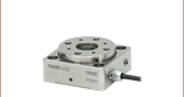
- 回転ステージPDR1C/M
- 光学式エンコーダ付き回転ステージPDXR1/M
このソフトウェアパッケージには2つの使い方があります。1つはGUI(グラフィカルユーザーインターフェイス)ユーティリティを用いる方法で、コントローラの直接的な操作や制御をすぐに行なうことができます。もう1つはサードパーティ開発用の一連のプログラミングインターフェイス(LabVIEW™/C++/Python SDK)を用いる方法で、カスタム仕様の位置決めやアライメント用のプログラムをご希望の開発言語で簡単に作成することができます。
ソフトウェア
Kinesisバージョン1.14.52
このKinesisソフトウェアパッケージには、当社のKinesisシステムコントローラを制御するためのGUIが含まれています。
下記もご用意しております。
- 通信プロトコル

Figure 58A KinesisソフトウェアのGUI画面
当社のKinesis®ソフトウェアパッケージを用いて、当社の様々なモーションコントローラを駆動することができます。このソフトウェアは小型で低出力のシングルチャンネルドライバ(K-Cubes™など)から、高出力でマルチチャンネルのベンチトップ型ユニットやモジュール型の19インチラックナノポジショニングシステム(ラックシステムMMR60x)まで、当社Kinesisシリーズの様々なモーションコントローラの制御用にご使用いただけます。
Kinesisソフトウェアでは.NETコントロールを使用できるため、最新のC#、Visual Basic、LabVIEW™、あるいはその他の.NET対応言語を使用してカスタムプログラムを作成することができます。.NETフレームワークの使用を想定していないアプリケーションのために、ローレベルのDLLライブラリも含まれています。中央シーケンスマネージャ(Central Sequence Manager)は、当社のすべてのモーションコントロール用ハードウェアの統合と同期の機能をサポートしています。
この共通のソフトウェアプラットフォームにより、ユーザは単一のソフトウェアツールを習得するだけで、あらゆるモーションコントロールデバイスを1つのアプリケーション内で組み合わせて使用することができます。このように1軸システム用から多軸システム用までのあらゆるコントローラを組み合わせ、それら全てを1台のPCの統合されたソフトウェアインターフェイスから制御できます。
このソフトウェアパッケージには2つの使い方があります。1つはGUI(グラフィカルユーザーインターフェイス)ユーティリティを用いる方法で、コントローラの到着後すぐに直接的な操作と制御を行なうことができます。もう1つは一連のプログラミングインターフェイスを用いる方法で、ご希望の開発言語によりカスタム仕様の位置決めやアライメント用のプログラムを簡単に作成することができます。
Kinesis®ソフトウェアでは新しい.NETコントロールが使用でき、最新の最新のC#, Visual Basic, LabVIEW™、ほかの.NET対応言語を使用する開発者がカスタムにプログラムを作成することもできます。
C#
このプログラミング言語はマルチプログラミングパラダイムやマルチプログラミング言語が使用可能となるよう設計されているため、複雑な問題が簡単かつ効率的に解決できます。型付け、命令型、宣言型、関数型、ジェネリック、オブジェクト指向、そしてコンポーネント指向が含まれます。 この共通のソフトウェアプラットフォームにより、1セットのソフトウェアツールを習得するだけで、あらゆるKinesisコントローラを簡単に組み合わせることができます。このようにして1軸システムのコントローラから多軸システムのコントローラまで、様々なコントローラを組み合わせ、全てを1台のPCのソフトウェアインターフェイスから制御することが可能となりました。
Kinesisシステムソフトウェアを使用するには2つの手段があります。コントローラを直接つないで制御を行なう付属のGUI(グラフィカルユーザーインターフェイス)ユーティリティ、またはご希望の開発言語でカスタム仕様の位置決めやアライメントを簡単にプログラムできる一連のプログラミングインターフェイスです。
Kinesisモーションコントロールライブラリの構築の参考となる実行可能なプロジェクト機能拡張例については下のリンクをクリックしてください。なお、Quick Startのプロジェクト例の実行には別の統合開発環境(IDE)(Microsoft Visual Studioなど)が必要です。C#のプロジェクト例はKinesisソフトウェアパッケージに付属する.NETコントロールで実行可能です(詳細は「Kinesisソフトウェア」タブをご覧ください)。
 | Click Here for the Kinesis with C# Quick Start Guide Click Here for C# Example Projects Click Here for Quick Start Device Control Examples | |
LabVIEW
LabVIEWは、.Netコントロールを介してKinesisベースのコントローラとの通信に使用できます。LabVIEWでは、ツールとオブジェクトでフロントパネルとして知られるユーザーインターフェイスを構築した後、グラフィカル表記の関数を使ってコードを追加し、フロントパネルのオブジェクトを制御します。下記のLabVIEWチュートリアルでは.Netコントロールを使用してLabVIEW内Kinesis駆動デバイス用の制御GUIを作成するための情報をご提供しています。 LabVIEWでコントローラを制御する基本的な方法や、LabVIEW GUIを用いてデバイスを操作する前に行うべき設定の手順についても解説しています。
 | Click Here to View the LabVIEW Guide Click Here to View the Kinesis with LabVIEW Overview Page | |
| Posted Comments: | |
| No Comments Posted |
電動リニアステージ
電動の直線移動ステージとしては、ピエゾ駆動の20 µm移動ステージからダイレクトドライブ方式の600 mm移動ステージまで、様々な最大移動量の製品をご用意しております。ステージの多くは、それらを用いてXY軸やXYZ軸などの多軸ステージを構築することができます。ファイバ結合用としては、多軸ステージのページをご覧ください。標準の電動ステージを用いるよりも精密な調整が可能です。直線移動ステージのほかに、電動の回転ステージおよびゴニオステージもご用意しております。また手動移動ステージもございます。
ピエゾステージ
これらのステージでは、様々な駆動機構にピエゾ素子が組み込まれています。ステージORIC®シリーズでは、「スティック-スリップ」と呼ばれる摩擦特性を利用したピエゾ慣性アクチュエータが用いられており、それにより長い移動距離が得られています。当社のモジュール式クイック接続型移動ステージXR25シリーズは、同じ原理で動作するピエゾ慣性アクチュエータPIA25で駆動できます。移動ステージNanoflex™シリーズは、手動アクチュエータに加えて標準的なピエゾアクチュエータが用いられています。ステージElliptec®シリーズでは共振ピエゾモータが用いられており、共振に伴うモータ先端の楕円形の動きで可動プラットフォームを押したり引いたりします。Z軸ステージLPS710E/Mにはピエゾ移動に対する機械的な増幅機構が組み込まれており、またそれに適したコントローラが付属しています。
| Piezoelectric Stages | ||||
|---|---|---|---|---|
| Product Family | ORIC® PDXZ1 Closed-Loop 4.5 mm Vertical Stage | ORIC® PD2 Open-Loop 5 mm Stage | ORIC® PDX2 Closed-Loop 5 mm Stage | ORIC® PDX4 Closed-Loop 12 mm Stage |
| Click Photo to Enlarge |  |  |  | 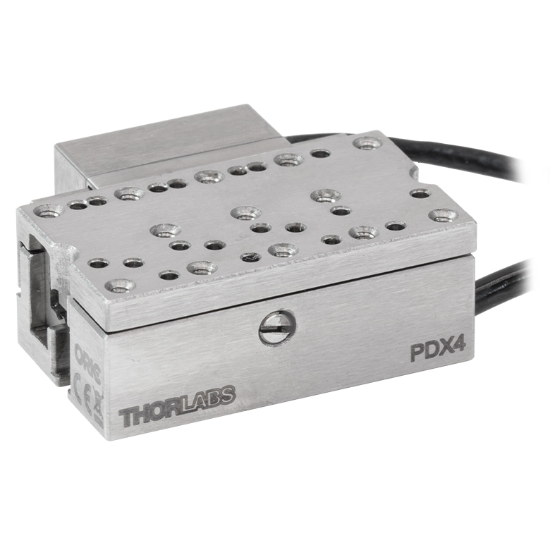 |
| Travel | 4.5 mm | 5 mm | 12 mm | |
| Speed | 1 mm/s (Typ.)a | 10 mm/s (Typ. Max)b | 8 mm/s (Typ.)c | 15 mm/s (Typ.)a |
| Drive Type | Piezoelectric Inertia Drive | |||
| Possible Axis Configurations | Z | X, XY, XYZ | ||
| Mounting Surface Size | 45.0 mm x 42.0 mm | 13.0 mm x 13.0 mm | 13.0 mm x 23.0 mm | |
| Additional Details | ||||
| Piezoelectric Stages | |||||
|---|---|---|---|---|---|
| Product Family | ORIC® PD1 Open-Loop 20 mm Stage | ORIC® PD1D Open-Loop 20 mm Monolithic XY Stage | ORIC® PDX1 Closed-Loop 20 mm Stage | ORIC® PD3 Open-Loop 50 mm Stage | |
| Click Photo to Enlarge |  |  |  |  | |
| Travel | 20 mm | 50 mm | |||
| Speed | 3 mm/s (Typ. Max)a | 20 mm/s (Typ. Max)b | 10 mm/sc | ||
| Drive Type | Piezoelectric Inertia Drive | ||||
| Possible Axis Configurations | X, XY, XYZ | XY, XYZ | X, XY, XYZ | X, XY, XYZ | |
| Mounting Surface Size | 30 mm x 30 mm | 80 mm x 30 mm | |||
| Additional Details | |||||
| Piezoelectric Stages | |||||||
|---|---|---|---|---|---|---|---|
| Product Family | Nanoflex™ 20 µm Stage with 5 mm Actuator | Nanoflex™ 25 µm Stage with 1.5 mm Actuator | Modular XR25 Series 25 mm Stage | Elliptec® 28 mm Stage | Elliptec® 60 mm Stage | LPS710E 1.1 mm Vertical Stage | |
| Click Photo to Enlarge |  |  | 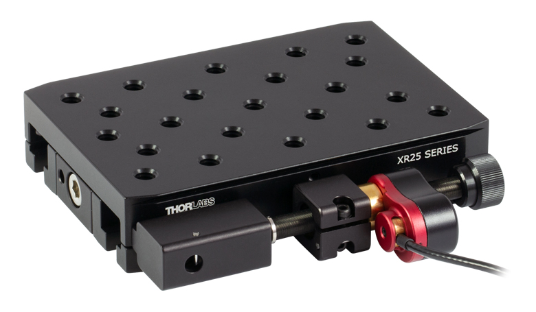 |  |  |  | |
| Travel | 20 µm + 5 mm Manual | 25 µm + 1.5 mm Manual | 25 mm | 28 mm | 60.0 mm | 1.1 mm | |
| Maximum Velocity | - | ≤3.6 mm/mina | 180 mm/s | 90 mm/s | - | ||
| Drive Type | Piezo with Manual Actuator | Piezo Inertia Drive | Resonant Piezoelectric Motor | Amplified Piezo | |||
| Possible Axis Configurations | X, XY, XYZ | X, XY, YZ, XZ, XYZ | X | Z | |||
| Mounting Surface Size | 75 mm x 75 mm | 30 mm x 30 mm | 110.0 mm x 75.7 mm | 15 mm x 15 mm | 21 mm x 21 mm | ||
| Additional Details | |||||||
ステッピングモーターステージ
こちらの移動ステージは脱着型あるいは内蔵型のステッピングモータを用いており、また300 mmまでの長い移動量が可能です。これらのステージの多くは多軸移動機能を有していたり(PLSXY)、あるいは多軸ステージを組み立てることが可能であったりします(PLSX、クイック接続型XR25シリーズ、LNRシリーズ、NRTシリーズ、LTSシリーズ)。ステージMLJ150/Mは高荷重にも対応する垂直移動ステージです。
| Stepper Motor Stages | |||||
|---|---|---|---|---|---|
| Product Family | MVSN1(/M) 13 mm Vertical Stage | PLS Series 1" Stages | Modular XR25 Series 25 mm Stage | LNR Series 25 mm Stage | LNR Series 50 mm Stage |
| Click Photo to Enlarge | 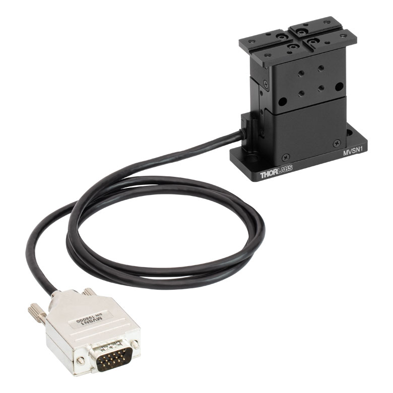 | 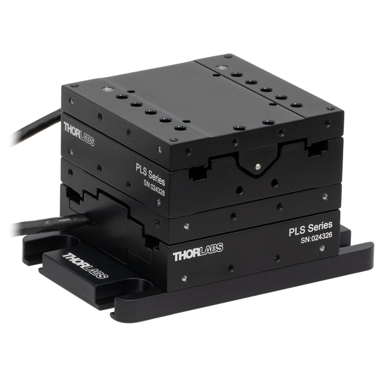 | 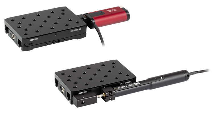 |  | 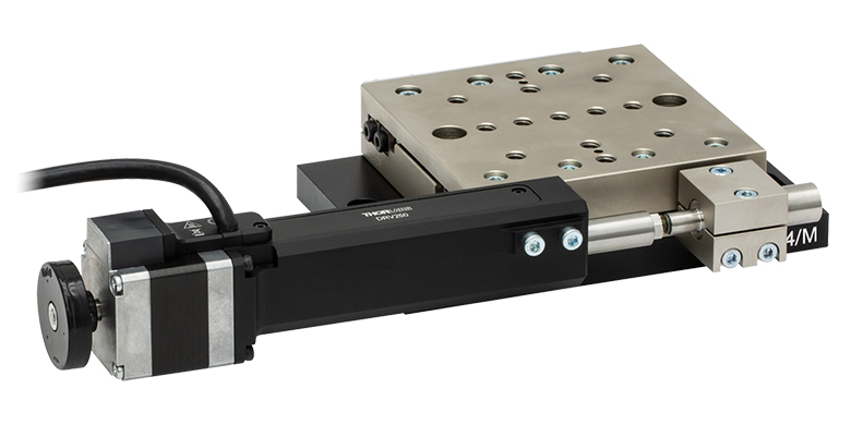 |
| Travel | 13 mm | 1" (25.4 mm) | 25 mm | 25 mm | 50 mm |
| Maximum Velocity | 5.0 mm/s | 7.0 mm/s | 2.0 mm/s | 2.0 mm/s | 50 mm/s |
| Possible Axis Configurations | Z | X, XY | X, XY, YZ, XZ, XYZ | X, XY, XYZ | X, XY, XYZ |
| Mounting Surface Size | 24.5 mm x 50.0 mm | 3" x 3" (76.2 mm x 76.2 mm) | 110.0 mm x 75.7 mm | 60 mm x 60 mm | 100 mm x 100 mm |
| Additional Details | |||||
| Stepper Motor Stages | ||||||
|---|---|---|---|---|---|---|
| Product Family | NRT Series 100 mm Stage | NRT Series 150 mm Stage | LTS Series 150 mm Stage | LTS Series 300 mm Stage | MLJ250 50 mm Vertical Stage | |
| Click Photo to Enlarge |  |  |  |  |  | |
| Travel | 100 mm | 150 mm | 150 mm | 300 mm | 50 mm | |
| Maximum Velocity | 30 mm/s | 50 mm/s | 3.0 mm/s | |||
| Possible Axis Configurations | X, XY, XYZ | X, XY, XYZ | Z | |||
| Mounting Surface Size | 84 mm x 84 mm | 100 mm x 90 mm | 148 mm x 131 mm | |||
| Additional Details | ||||||
DCサーボモーターステージ
脱着型あるいは内蔵型のDCサーボモータを用いた直線移動ステージをご用意しております。これらのステージは薄型で、多軸ステージの構築が可能です。
| DC Servo Motor Stages | |||||
|---|---|---|---|---|---|
| Product Family | MT Series 12 mm Stages | PT Series 25 mm Stages | Modular XR25 Series 25 mm Stage | MTS Series 25 mm Stage | MTS Series 50 mm Stage |
| Click Photo to Enlarge |  |  | 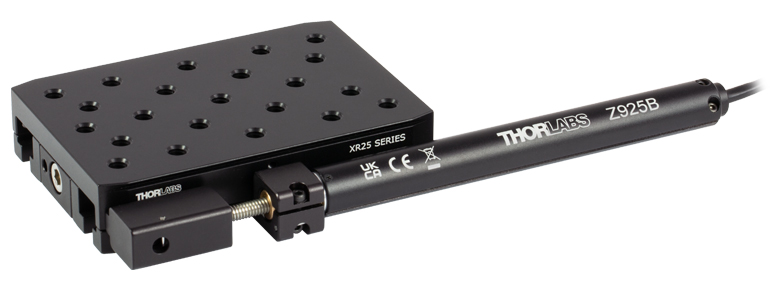 |  |  |
| Travel | 12 mm | 25 mm | 25 mm | 25 mm | 50 mm |
| Maximum Velocity | 2.6 mm/s | 2.6 mm/s | 2.4 mm/s | ||
| Possible Axis Configurations | X, XY, XYZ | X, XY, YZ, XZ, XYZ | X, XY, XYZ | ||
| Mounting Surface Size | 61 mm x 61 mm | 101.6 mm x 76.2 mm | 110.0 mm x 75.7 mm | 43 mm x 43 mm | |
| Additional Details | |||||
| DC Servo Motor Stages | ||||
|---|---|---|---|---|
| Product Family | M30 Series 30 mm Stage | M30 Series 30 mm Monolithic XY Stage | M150 Series 150 mm XY Stage | KVS30 30 mm Vertical Stage |
| Click Photo to Enlarge |  |  |  |  |
| Travel | 30 mm | 150 mm | 30 mm | |
| Maximum Velocity | 2.4 mm/s | X-Axis: 170 mm/s Y-Axis: 230 mm/s | 8.0 mm/s | |
| Possible Axis Configurations | X, Z | XY, XZ | XY | Z |
| Mounting Surface Size | 115 mm x 115 mm | 272.4 mm x 272.4 mm | 116.2 mm x 116.2 mm | |
| Additional Details | ||||
ダイレクトドライブステージ
こちらの薄型ステージにはブラシレスDCサーボモータが内蔵されており、バックラッシュの無い高速移動が可能です。電源が入ってないときは、ステージのプラットフォームにはほとんど慣性が無く、実質的にフリーラン状態になります。そのため電源が入ってないときにステージのプラットフォームが定位置に留まる必要のある用途には適していません。これらのステージを垂直方向に取付けることは推奨しません。
| Direct Drive Stages | |||||
|---|---|---|---|---|---|
| Product Family | DDS Series 50 mm Stage | DDS Series 100 mm Stage | DDS Series 220 mm Stage | DDS Series 300 mm Stage | DDS Series 600 mm Stage |
| Click Photo to Enlarge |  |  |  |  |  |
| Travel | 50 mm | 100 mm | 220 mm | 300 mm | 600 mm |
| Maximum Velocity | 500 mm/s | 300 mm/s | 400 mm/s | 400 mm/s | |
| Possible Axis Configurations | X, XY | X, XY | X | X | |
| Mounting Surface Size | 60 mm x 52 mm | 88 mm x 88 mm | 120 mm x 120 mm | ||
| Additional Details | |||||

 ズーム
ズーム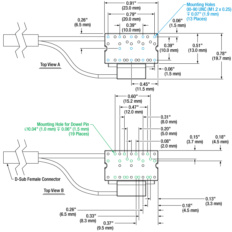
Click for Details
Figure G1.1 This schematic shows the top plate mounting features of the PDX4(/M) linear stage. Dimensions for the metric stage are given in parentheses.
Includes:
- Linear Stage with Integrated Cable, D-Sub Female Connector
- Six 00-90 (M1.2 x 0.25) Slotted Pan Head Screws
- Six Ø1 mm Dowel Pins
- Individual Test Data Certificate
- Open- and Closed-Loop Operation Supported
- Optical Encoder Provides Resolution Up to 12.5 nm
- <5 mrad XY Stacked Orthogonality
- Moves at a Typical Speed of Up to 15 mm/s (Closed Loop)
- Integrated 1.5 m (4.9 ft) Cable with D-Sub Female Connector
- Requires the PDXC or PDXC2 Piezo Inertia Controller (Sold Separately Below)
- Each Stage Individually Tested and Shipped with Test Data Certificate
This ORIC® piezo inertia stage with an optical encoder is able to operate in both open- and closed-loop modes, can support loads up to 1 kg, and operate at speeds up to 15 mm/s with no backlash. The piezo inertia drive is self-locking when the stage is at rest and no power is supplied to the piezo, making these actuators ideal for set-and-hold applications that require nanometer resolution and long-term alignment stability. See the Specs tab for detailed specifications. The configuration of mounting holes on the top plate of the stage is shown in Figure G1.1.
After each stage is manufactured, the pitch and yaw of the stage are tested. This ensures that each stage meets the stated specifications over the full translation range of the stage. A summary of the test results is provided on a data sheet that ships with each stage. A sample data sheet can be viewed here.
The stage should be placed on a surface with flatness ≤5 µm. The PD4T(/M), PD4U(/M), PD1B3(/M), and PD4Z(/M) mounting adapters (sold below) provide a mounting surface with precise flatness to avoid warping the stage when mounting it to a table or breadboard surface.
Each stage has an integrated 1.5 m cable with a 15-pin D-sub connector that can connect directly to a PDXC or PDXC2 controller. If additional cable length is needed, the 3 m long PDXCE Extension Cable (available separately below) can be used. Due to the capacitance of the cables, do not use cables longer than 4.5 m in total when connecting the stage to a PDXC or PDXC2 controller.
Note: The PDX4(/M) stage is only compatible with the PDXC and PDXC2 controllers. The stage's speed is adjusted by the voltage amplitude with constant 20 kHz driving frequency in both open-loop and closed-loop mode, or at lower driving frequencies using open-loop mode with the PDXC2 compact controller. Since 20 kHz is an inaudible frequency, under such conditions the stage operates quietly. At different driving frequencies, the stage may make a high-pitched noise or generate some heat; this is normal behavior in the performance of the device and does not indicate a fault condition.

 ズーム
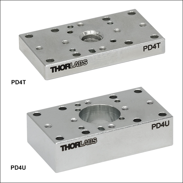
ズーム- Additional Mounting Options with 8-32 (M4 x 0.7) Threaded Hole or #8 (M4) Counterbore
- Same 23.0 mm x 13.0 mm Footprint as PDX4(/M) Stage Surface
These adapter plates provide alternative mounting holes for the PDX4(/M) stage. The PD4T(/M) adapter plate is 0.12" (3.0 mm) thick and features a central 8-32 (M4 x 0.7) threaded hole accessible from the bottom side of the plate, making it ideal for post mounting as shown in Figure G2.1. A PDX4(/M) 12 mm stage can be mounted to a PD1 series 20 mm linear stage using the PD4U(/M) adapter and a PD1T(/M) adapter. The PD4U(/M) adapter plate is 0.24" (6.0 mm) thick and features a central #8 (M4) counterbore, primarily designed to serve as a mounting adapter to provide a base with ≤5 µm flatness.
Each adapter matches the footprint of the PDX4(/M) stage and can be secured to the top or bottom of the stage using two 00-90 (M1.2 x 0.25) slotted pan head screws (included with the stage) and two Ø1 mm dowel pins (included with the stage). The top and bottom faces of both adapters provide features for compatibility with the PDX4(/M) stage and PD4Z(/M) bracket. The bottom faces (illustrated in the detailed versions of Figures G2.2 and G2.3) include eight #00 (M1.2) counterbores, four Ø1 mm dowel pin holes, and six 00-90 (M1.2 x 0.25) threaded through holes. The top faces (illustrated in Figures G2.2 and G2.3) feature six 00-90 (M1.2 x 0.25) threaded through holes, five Ø1 mm dowel pin holes, and one mounting slot for a Ø1 mm dowel pin, which provides 0.5 mm of alignment flexibility. The PD4T(/M) adapter bottom face also includes an 8-32 (M4 x 0.7) threaded mounting hole, while the PD4U(/M) adapter top face includes a counterbore for an 8-32 (M4 x 0.7) cap screw.
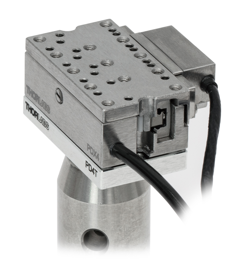
Click to Enlarge
Figure G2.1 The PDX4(/M) stage can be mounted on a Ø1/2" post using the PD4T(/M) adapter.
Click for Details
Figure G2.2 A schematic is shown for the PD4T(/M) mounting adapter plate. Dimensions for the metric adapter plate are given in parentheses.
Click for Details
Figure G2.3 A schematic is shown for the PD4U(/M) mounting adapter plate. Dimensions for the metric adapter plate are given in parentheses.

 ズーム
ズーム
Click for Details
Figure G3.2 Mechanical Drawing for the PD1B3(/M) Adapter Plate. See Table G3.3 for descriptions of the hole labels. Dimensions for the metric version of the adapter plate are given in parentheses.

- Provide Flat Surface for Mounting ORIC Stages
- Passivated Stainless Steel Construction
- Reduces Stage Warping When Mounting to Table or Breadboard
- Dimensions (L x W x H): (65.0 mm x 65.0 mm x 10.0 mm)
Thorlabs' PD1B3(/M) Universal Adapter Plate provides a flat surface (flatness ≤5 µm) for mounting any of the ORIC piezo inertia stages. Mounting holes are labeled in the mechanical drawing in Figure G3.2 corresponding to Table G3.3. The four 4-40 threaded holes are 30 mm cage system compatible, and two 1/4"-20 (M6) screws are included for mounting to breadboards.
If the stage is mounted on a surface with >5 µm flatness (as with most breadboards and optical tables), the velocity variation and pitch/yaw of the stage may suffer due to the stage warping. Mounting the stage on the adapter drastically reduces the amount the stage warps when mounted on a table or breadboard with insufficient flatness.
| Table G3.3 Hole Descriptions | ||||
|---|---|---|---|---|
| Labela | Holes/Slots Patternb | Spacingb (Stage Compatibility) | Threading Depth | Places |
| A | 1/4"-20 (M6) | 1" x 2" (25 x 50 mm) | Through | 6 |
| B | Ø2 mm Dowel Pin Holes |
16 x 16 mm | 1.5 mm | 4 |
| C | 4-40 | 30 x 30 mm (Item #s PDR1(/M), PDR1V(/M)) | 3.5 mm | 4 |
| D | 1/4" (M6) Counterbored Slot | 1" to 2" (25 to 50 mm) | N/A | 4 |
| E | 00-90 (M1.2) | 10 x 10 mm (Item #s PD2(/M), PDX2(/M), PDX4(/M)) | 3 mm | 4 |
| F | #8 (M4) Counterbored Slot | 1.25" (31.25 mm) | N/A | 1 |
| G | 2-56 (M2) | 27.0 x 23.4 mm (Item #s PDXZ1(/M), PD1(/M), PD1V(/M), PDX1(/M), PDX1A(/M), PDX1AV(/M), PD1D(/M), PDR1C(/M)) / 40.8 x 30 mm |
7 mm | 8 |
| H | 8-32 (M4) | 2" (50 mm) (Item # PD3(/M)) / 2" x 2" (50 x 50 mm) (Item # PDXR1(/M)) |
7.8 mm | 4 |

 ズーム
ズーム
Click for Details
Figure G4.2 PD4Z(/M) Bracket Schematic with Metric Bracket Dimensions Given in Parentheses
Click to Enlarge
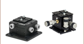
Figure G4.1 Three PDX4(/M) stages can be mounted in an XYZ configuration using the PD4Z(/M) right-angle bracket.
- Mounts PDX4(/M) Stage at 90° for Vertical or Horizontal Translation
- Enables Vertical Z-, XZ-, or XYZ-Axis Configurations
The PD4Z(/M) right-angle bracket allows the user to mount a PDX4(/M) stage at 90°, as shown in Figure G4.1. The bracket can be secured to the top plate of the stage, a PD4T(/M) adapter, or PD4U(/M) adapter using two 00-90 (M1.2 x 0.25) slotted pan head screws and the #00 (M1.2) counterbored holes in the base of the bracket. The vertical stage can then be mounted on the bracket using a second set of pan head screws and dowel pins. Eleven 00-90 (M1.2 x 0.25) mounting holes and twelve Ø1 mm dowel pin holes are located on the larger (vertical) face for precise alignment (illustrated in Figure G4.2). The base has three Ø1 mm dowel pin holes and three mounting slots for Ø1 mm dowel pins providing 0.5 mm of alignment flexibility (illustrated in the detailed version of Figure G4.2).
Note: Long-term operation (>1 km distance) when mounted vertically may cause rail creep, leading to a reduced travel range. To restore the stage performance, we recommend mounting the stage horizontally after approximately 0.5 km of translation in a vertical orientation and translating it back and forth across the full travel range several times.

 ズーム
ズーム
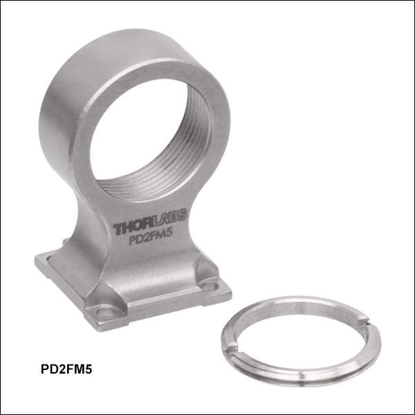
Click for Details
Figure G5.2 PD2FM5 Fixed Optic Mount Stage Mounting Features
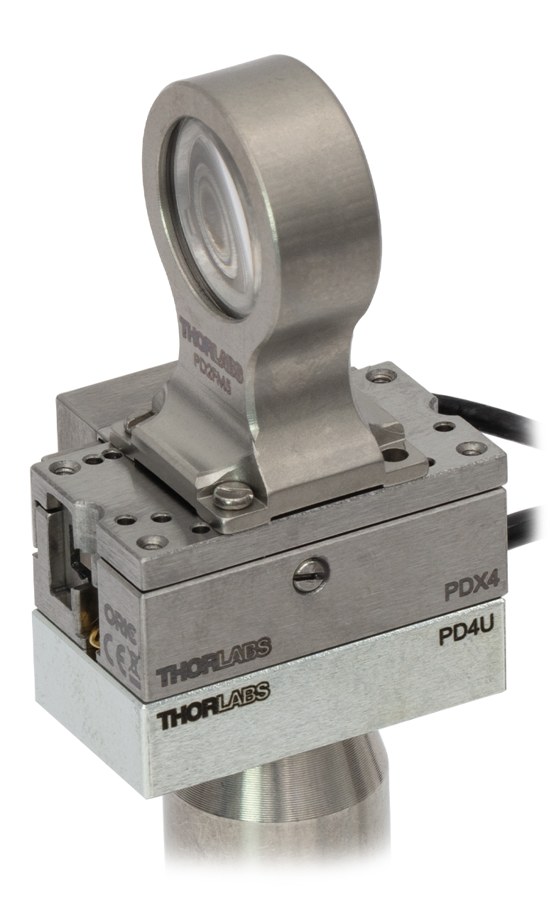
Click to Enlarge
Figure G5.1 The PDX4 stage with the PD2FM5 mount provides 12 mm of translation along the optical axis.
- Mount Ø1/2" (12.7 mm) Optics to the PDX4(/M) Stage
- Mount Optic at 0° or 90° to the Stage's Translation Axis
- SM05-Threaded Optic Bore with Included POLARIS-SM05RR Retaining Ring
- Mounts Ø1/2" Optics up to 0.15" (3.9 mm) Thick
- Included Mounting Components:
- Two Ø1 mm x 3 mm Long Dowel Pins
- Two 00-90 Brass, Slotted Round Head Screws
- Two M1.2 Stainless Steel, Slotted Cheese Head Screws
The PD2FM5 Fixed Optic Mount is designed to hold a Ø1/2" optic up to 0.15" (3.9 mm) thick and can be mounted to the top platform of a PDX4(/M) 12 mm piezo inertia stage via four 00-90 (M1.2 x 0.25) threaded holes separated by 10.00 mm. When the PD2FM5 is mounted to the PDX4(/M) stage, the height to the optical axis is 24.55 mm.

 ズーム
ズーム| Key Specificationsa | ||
|---|---|---|
| SMC Port | Number of Ports | Two |
| Voltage | 0 to 40 V | |
| Frequency | 20 kHz Max | |
| D-Sub Port | Number of Ports | One |
| Voltage | -10 to 50 V | |
| Frequency | 20 kHz Max | |
| Max Current Limit | 10 A | |
| Front USB | Type A, USB Host 2.0 | |
| Back USB | Type B, USB Device 2.0 | |
| Voltage of Analog In/Out | -10 to 10 V, ±2% | |
| Voltage of Trigger In/Out | 0 to 5 V, TTL | |
| Input Power | 100 - 240 VAC, 50 - 60 Hz | |
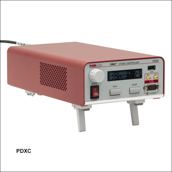
- 詳細な仕様については下の赤いアイコン(
 )をクリックしてマニュアルをご覧ください。
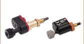
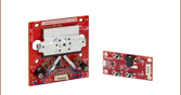
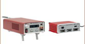
- PDシリーズピエゾ慣性アクチュエータ付き直線移動ステージ、垂直移動ステージPDXZ1/M、および回転ステージPDR1C/MとPDXR1/M用コントローラ
- 開ループおよび閉ループの両動作をサポート
- SMCおよび15ピンDサブポートが使用可能
こちらのコントローラは、当社のピエゾ慣性アクチュエータ付きの直線移動ステージ、垂直移動ステージPDXZ1/M、そして回転ステージPDR1C/M、PDXR1/Mの制御用として設計されています。開ループステージ制御用のSMC出力端子が2チャンネル、開ループまたは閉ループステージ制御用の15ピンDサブ出力ポートが1チャンネル付いています。Dサブコネクタ付きのORICシリーズステージを使用するうえで延長ケーブルが必要な場合には、PDXCEをご使用いただけます(別売り、下記参照)。
組込まれたソフトウェアにより、フロントパネルのボタン、LCDディスプレイ、およびノブを使用して、このユニットをフル制御できます。また、組込みの外部トリガーモードはシングルチャンネル動作をサポートしています。複数のコントローラを接続することで、Dサブモードでラスタ走査のようなマルチチャンネル動作が可能です。ユーザは、PCに接続しなくても、出力ポートの選択、開ループ/閉ループのモード切り替え、ホーミングやエンコーダの校正などを行うことができます。ユニット上での制御のほかに、USB接続を利用してソフトウェアのプラットフォームで簡単にPC制御を行うこともできます。
ユニットには日本国内用の電源コードが付属します。すべての用途において、お手持ちの電源ソケットに適したプラグの付いた、IEC320準拠の電源コードをご使用ください。また、背面パネルに記載された定格電源電圧が、日本国内の電源に合致していることをご確認ください。
詳細については、製品紹介ページをご参照ください。

 ズーム
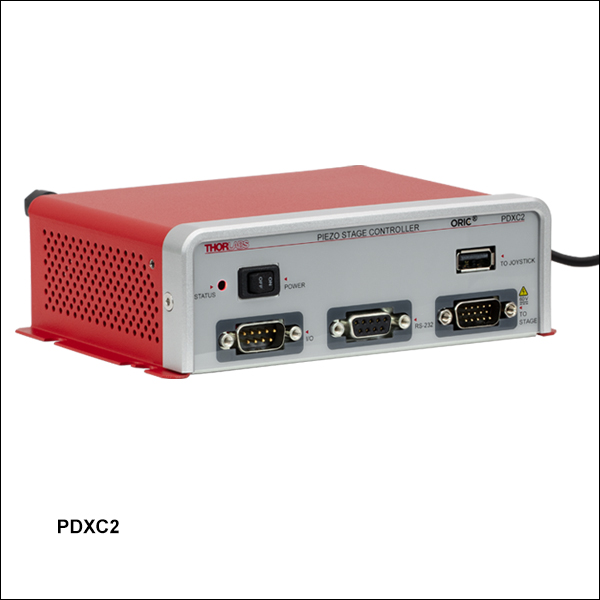
ズーム| Key Specificationsa | ||
|---|---|---|
| Performance Specificationsa | ||
| D-sub Port | Number of Ports | One |
| Voltage | 0 to 56 V | |
| Frequency | 20 kHz Max | |
| Max Current Limit | 10 A | |
| Front USB | Type A, USB HID Host | |
| Back USB | Type B, USB Device 2.0 | |
| I/O Port | Voltage of Analog In/Out | -10 to 10 V, ±2% |
| Voltage of Trigger In/Out | 0 to 5 V, TTL | |
| Ethernet PC Communication | One RJ-45 Port | |
| Dimensions (L x W x H) | 115.2 mm x 150.0 mm x 48.5 mm (4.54” x 5.91” x 1.91”) | |
| Weight | 0.53 kg | |
| Input Power | 12 V, 3 A DAC | |
- 詳細な仕様は下の赤いアイコン() をクリックしてマニュアルをご覧ください。
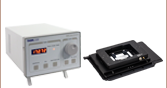
- ORICシリーズのピエゾ慣性アクチュエータ付き直線移動ステージ、垂直移動ステージPDXZ1/M、および回転ステージPDR1C/MとPDXR1/M用のコントローラ
- コンパクトな設計、ソフトウェアKinesis®による制御
- 開ループおよび閉ループの両動作をサポート
- エネルギー効率の高いスイッチングアンプ回路によりピーク出力電流10 Aを実現
- 設定可能な高速通信インターフェイス:USB 2.0、ギガビットイーサネット、デジタルI/0、アナログI/0
- パルスレートの範囲:800 Hz~20 kHz
小型コントローラPDXC2 は、当社のピエゾ慣性アクチュエータで動作するORICシリーズの直線移動ステージ、垂直移動ステージPDXZ1/M、および回転ステージPDR1/MとPDXR1/Mの制御用として設計されています。1チャンネルの開ループまたは閉ループのステージを制御できるポート(15ピンDサブ)が付いています。Dサブ-SMCアダプターケーブルPDXC2AD(下記参照)を使用すると、SMCコネクタを有するステージに接続して開ループ動作での操作ができます。
コントローラPDXC2は、背面パネルのUSBポートまたはイーサネットポートからPCに接続できます。開ループと閉ループのモード切替え、ホーミング動作の実行、パラメータの最適化等の動作パラメータとシステム操作のすべては、Kinesis®ソフトウェア(上の「Kinesisソフトウェア」タブからダウンロードできます)を搭載したPCで制御できます。トリガーモードや移動パラメータなどを設定することで、ラスター走査といった動作を構成することができます。ORICシリーズの特定のエンコーダ付きステージ(型番PDX1/M、PDX1A/M、PDX1AV/M、PDXR1/Mのみ)はモーションコントロールソフトウェアページ内のPDXC2 Calibration Toolを用いて校正できます。詳細はマニュアルをご覧ください。コマンドライン制御もUSBとRS-232のポートを用いて実行できます。
PDXC2は付属の12 VDC電源DS12 (入力電圧100~240 VAC、国内用AC電源ケーブル付属)で電源供給されます。 すべての用途において、お使いの電源ソケットに適したプラグの付いた、IEC320準拠の電源コードをご使用ください。また、背面パネルに記載された定格電源電圧が、日本国内の電源に合致していることをご確認ください。
詳細は製品紹介ページをご参照ください。

 ズーム
ズーム
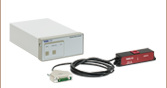
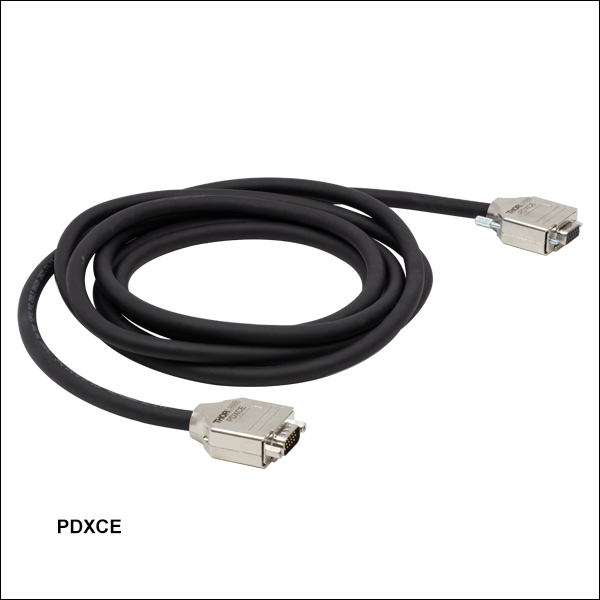
Click to Enlarge
DB15オス-DB15メス

- PDXZ1/M、PD2/M、PDX2/M、PDX4/M、PDX1/M、PDX1A/M、PDX1AV/M、PD3/M、PDXR1/Mのメス型Dサブコネクタと、ピエゾ慣性ステージ用コントローラのPDXCやPDXC2を接続
- 長さ3 mの延長用ケーブル
メス型Dサブコネクタ付きのORICステージとピエゾ慣性ステージ用コントローラORIC PDXCまたはPDXC2を接続するとき、必要に応じて長さ3 mの延長ケーブルPDXCEを用いてケーブルを延長することができます。ケーブルの静電容量により、各ステージには推奨する最大ケーブル長があります。延長ケーブルを追加する前に、各ステージの仕様をご確認ください。