電動アクチュエーター、移動量25 mm
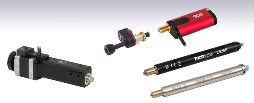
- Piezo Inertia, DC Servo, or Stepper Actuators with 25 mm of Travel
- Load Capacities Up to 55 lbs (25 kg) Available
- Maximum Speeds Up to 50 mm/s Available
- Compatible with a Wide Range of Stages
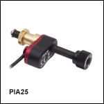
PIA25
Piezo Inertia Actuator
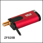
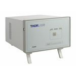
ZFS25B
Compact Stepper Motor Actuator
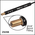
Z925B
DC Servo Actuator
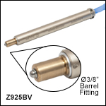
Z925BV
Vacuum-Compatible DC Servo Actuator
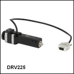
DRV225
Trapezoidal Stepper Motor Actuator

Please Wait
| Item # | ZFS25B | ZST225B | DRV225 | Z925B | Z925BV | PIA25 | PIA25VF |
|---|---|---|---|---|---|---|---|
| Travel | 25 mm (0.98") | ||||||
| Motor Type | 2-Phase Stepper | DC Servo w/ Encoder |
Piezo Inertia Acuator | ||||
| Mounting | Ø3/8" (Ø9.525 mm) Barrel | Two M4 Cap Screws | Ø3/8" (Ø9.525 mm) Barrel | ||||
| Vacuum Rating | N/A | N/A | 10-6 Torr | N/A | 10-6 Torr | ||
| Required Controller | KST201 | BSC201, BSC202, BSC203, or MST602 |
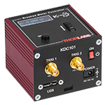
KDC101 | KIM001 or KIM101 | |||
Features
- 1" (25 mm) Travel
- Stepper Motor, Servo Motor, and Piezo Inertia Actuator Models
- Rotating and Non-Rotating Drive Tips
- Replace Micrometers on Manual Stages and Mounts
Thorlabs' Motorized Actuators are designed for use with optical positioning devices. They offer high resolution in lightweight packages, which makes these actuators ideally suited for demanding optical automation applications. These 1" (25 mm) travel motorized actuators are available with three drive types: 2-phase stepper motors, DC servos with encoders, or piezo inertia actuators. Vacuum-compatible models with DC servos or piezo inertia actuators provide functionality down to 10-6 Torr. See the table to the right for an overview of the available models or below for more details.
| Quick Links to Other Motorized Actuators | |||
|---|---|---|---|
| 10 mm (0.39") or Less Travel | 12 mm or 13 mm (1/2") Travel | 25 mm (1") Travel | 50 mm (2") Travel |
ZFS25B and ZST225B Actuators
Pin Diagram

High-Density D-Type Male 15 Pin Connector
15-Pin D-Sub Connector Pin Out
| Pin | Description | Pin | Description |
|---|---|---|---|
| 1 | Limit Ground | 8 | Reserved for Future Use |
| 2 | CCW Limit Switch | 9 | Reserved for Future Use |
| 3 | CW Limit Switch | 10 | Vcc (+5 VDC) |
| 4 | Motor Phase B - | 11 | Reserved for Future Use |
| 5 | Motor Phase B + | 12 | Reserved for Future Use |
| 6 | Motor Phase A - | 13 | Reserved for Future Use |
| 7 | Motor Phase A + | 14 | Reserved for Future Use |
| - | - | 15 | Ground |
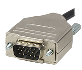
Click to Enlarge
High-Density D-Type Male 15 Pin Connector
DRV225 Actuator
Pin Diagram

High-Density D-Type Male 15 Pin Connector
15-Pin D-Sub Connector Pin Out
| Pin | Description | Pin | Description |
|---|---|---|---|
| 1 | Limit Grounda | 9 | Ident (for Future Use) |
| 2 | CCW Limit Switch | 10 | +5 V |
| 3 | CW Limit Switch | 11 | Reserved for Future Use |
| 4 | Motor Phase B -ve | 12 | Reserved for Future Use |
| 5 | Motor Phase B +ve | 13 | +5 V |
| 6 | Motor Phase A -ve | 14 | Reserved for Future Use |
| 7 | Motor Phase A +ve | 15 | Ground |
| 8 | Reserved for Future Use | - | - |

Click to Enlarge
High-Density D-Type Male 15 Pin Connector
Z925B Actuator
Pin Diagram

High-Density D-Type Male 15 Pin Connector
15-Pin D-Sub Connector Pin Out
| Pin | Description | Pin | Description |
|---|---|---|---|
| 1 | Ground (Limit and Vcc) | 9 | Resistive Identification |
| 2 | Forward Limit | 10 | +5 VDC |
| 3 | Reverse Limit | 11 | Encoder Channel A |
| 4 | Reserved for Future Use | 12 | Reserved for Future Use |
| 5 | Motor (-) | 13 | Encoder Channel B |
| 6 | Reserved for Future Use | 14 | Pin 2 Identification EEPROM |
| 7 | Motor (+) | 15 | Pin 1 Identification EEPROM |
| 8 | Reserved for Future Use |

Click to Enlarge
High-Density D-Type Male 15 Pin Connector
Z925BV Actuator
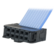
The vacuum-compatible cable integrated with the Z925BV actuator is terminated in a female IDC 10-Pin socket connector. A short converter cable, which adapts this female IDC socket connector to a D-type male HD15 pin connector, is included with the Z925BV actuator to facilitate connecting it to the recommended KDC101 controller. This converter cable, whose terminating connectors are shown below, is not vacuum compatible. Information describing the pin assignments for both the female IDC socket and male D-type HD connector (when it is connected to the female IDC socket connector) follows.
Pin Diagram
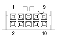
10 Pin Female IDC Socket Connector
(Amphenol T812 Series, 2.54 mm Pitch)
Female IDC 10-Pin Connector Pin Out
| Pin | Description | Pin | Description |
|---|---|---|---|
| 1 | Motor (+) | 6 | Motor (-) |
| 2 | Vcc | 7 | Limit Ground |
| 3 | Channel A | 8 | Reverse Limit |
| 4 | Channel B | 9 | Forward Limit |
| 5 | Ground | 10 | Not Connected |
Pin Diagram

High-Density D-Type Male 15 Pin Connector
Male HDDB15 Connector Pin Out
| Pin | Description | Pin | Description |
|---|---|---|---|
| 1 | Ground (Limit and Vcc) | 8 | Reserved For Future Use |
| 2 | Forward Limit | 9 | Ident Resistor |
| 3 | Reverse Limit | 10 | Vcc (+5 VDC) |
| 4 | Reserved For Future Use | 11 | Encoder Channel A |
| 5 | Motor (-) | 12 | Reserved for Future Use |
| 6 | Reserved for Future Use | 13 | Encoder Channel B |
| 7 | Motor (+) | 14, 15 | Reserved For Future Use |

Click to Enlarge
Connectors terminating the converter cable. The image on the left shows the high-density D-type male 15-pin connector, and the image on the right shows the 10-pin male IDC socket connector.
Example: Calculating the Linear Displacement per Microstep for Stepper Motor Driven Actuators
The ZFS series of stepper motor actuators have 24 full steps per revolution. When driven by the KST201 driver, there are 2048 microsteps per full step resulting in 49 152 microsteps per revolution of the motor. The output shaft of the motor goes into a 400:9 (~44.444:1) gear head. This requires the motor to rotate 44.444 times to rotate the 1.0 mm pitch lead screw one revolution, giving a linear displacement of 1.0 mm.
Number of microsteps per lead screw revolution is:
Number of Microsteps x Gearbox Ratio = 49 152 x 44 444 = 2 184 511.5 Microsteps per Lead Screw Revolution.
The theoretical linear displacement of the lead screw per microstep is:
1.0 mm / 2 184 511.5 = 0.46 x 10⁻⁶ mm = 0.46 nm.
Summary of Calculations for Stepper Motor Driven Actuators
| Item # | Required Driver | Full Steps per Revolution | Microsteps per Revolution | Gearbox Ratio | Displacement per Microstepa |
|---|---|---|---|---|---|
| ZFS25B | KST201 | 24 | 49 152 | 44.444:1 | 0.46 nm |
| ZST225B | 40.866:1 | 0.50 nm | |||
| DRV225 | BSC201, BSC202, BSC203, or MST602 |
200 | 409 600 | N/A | 2.4 nm |
Example: Calculating the Encoder Resoution for Z9 Series Servo Motor Driven Actuators
The Z9 series of servo motor driven actuators have 512 encoder counts per revolution of the servo motor. The output shaft of the motor goes into a 67.49:1 planetary gear head, requiring the motor to rotate 67.49 times to rotate the 1.0 mm pitch lead screw one revolution, giving a linear displacement of 1.0 mm.
The number of encoder counts per lead screw revolution is:
Number of Encoder Counts x Gearbox Ratio = 512 x 67.49 = 34 555 Encoder Counts per Lead Screw Revolution.
The theoretical encoder resolution (linear displacement of the lead screw per encoder count) is:
1.0 mm / 34 555 counts = 2.9 x 10⁻⁵ mm = 29 nm.
Summary of Calculations for Servo Motor Driven Actuators
| Item # | Required Driver | Encoder Counts per Revolution | Gearbox Ratio | Encoder Resolution |
|---|---|---|---|---|
| Z925B | KDC101 | 512 | 67.49:1 | 29 nm |
| Z925BV |
| Posted Comments: | |
Upasana Das
(posted 2024-10-03 12:17:22.887) I have been using two Motor Actuator with 25 mm Travel for my APD setup but when they move around 5 mm or more at a stretch it makes a loud whining noise. What can be the possible reason behind this sound and what to do for maintainance of these actuators? spolineni
(posted 2024-10-10 12:30:46.0) Thank you for reaching out. I will personally contact you to assist with troubleshooting the issue with your motor actuator. Franklin Wei
(posted 2024-06-24 18:38:20.267) We have an application which would benefit from a 50 mm version of the Z925B. Is there a chance this could be developed? cstroud
(posted 2024-06-26 11:11:40.0) Thanks for reaching out. I will pass along your feedback to our internal suggestion forum. Yu Chen
(posted 2023-12-10 00:20:42.793) I have the same problem as Martin Tmej mentioned. When connecting ZFS25B to a controller KST101 the actuator reports itself as ZST6(B) model. I noticed in the reply it said that a firmware update for the controller should solve this question. My question is where can I get the firmware update done? Thanks Victor Lorenz Fonfria
(posted 2022-09-08 10:09:28.75) Can I use the actuator Z825B to replace a micrometer in the stage LX30/M? The micrometers in LX30/M have a Ø3/8" barrel, so I guess I can replace them with Z825B, but I would like to have a confirmation. cwright
(posted 2022-09-09 05:17:59.0) Response from Charles at Thorlabs: Thank you for your query. Yes the Z825B could be used with the LX30/M as a replacement for the micrometer. Martin Tmej
(posted 2022-06-22 08:49:54.44) Hello, I connected the ZFS25B to a controller KST101 and the actuator reports itself as ZST6(B) model. There does not fit any calibration. I tried to change the actuator type through Kinesis application, but it does not allow it. Please, how can I change the actuator type?
Thanks, Martin Tmej cwright
(posted 2022-06-23 09:32:47.0) Response from Charles at Thorlabs: Thank you for your query. If the stage is not detected correctly then it may be that the controller requires a firmware update to account for a change of ident device. We will reach out to you to help with this. HYESANG KIM
(posted 2020-04-23 12:05:12.517) KDC101 with Z825B. Wanted to control them with matlab, and it worked a bit successfully.
I can use device.Home() and device.MoveTo(), but device.MoveToAt() or device.MoveContinuous() and several commands are not working with error : "Class 'Thorlabs.MotionControl.KCube.DCServoCLI.KCubeDCServo' does not have the appropriate method, property, field 'MoveToAt'.".
How can I use them? DJayasuriya
(posted 2020-04-24 09:30:11.0) Response from Dinuka at Thorlabs: Thank you for your feedback, I will be in contact with you directly to help troubleshoot your programming issues. himada
(posted 2018-11-04 21:58:18.32) Can we remove the spherical tip and attach another tip? rmiron
(posted 2018-11-05 06:40:18.0) Response from Radu at Thorlabs: Unfortunately, this is not possible with Z825B. I will relay your question internally so that it is taken into account when we design the next iteration of this product. chao.he
(posted 2018-06-07 15:19:34.433) Hi, I am using Z825B and the KDC101 to control. I can understand the calculation process and the resolution. But how could I know how many rotating steps (number on KDC101 display) corresponding to the real distance moving by one direction? For example, if I change the control number from 0 to 0.25 on KDC, what will be the real distance moving by the Z825B induced? Thanks rmiron
(posted 2018-06-11 05:53:03.0) Response from Radu at Thorlabs: I am afraid that I do not know what is the number on KDC101's display that you are referring to. By default, the controller only displays the current position in mm or degrees and the reading should be labelled accordingly. Therefore, no conversion should be necessary. I will contact you directly for clarification purposes. ruby.mchone
(posted 2015-04-24 16:12:26.65) Please provide details on designing the mating part to best press fit the actuator mounting the part. Thank you. bhallewell
(posted 2015-04-27 10:41:06.0) Response from Ben at Thorlabs: Thanks for your request here Ruby. This is dependent upon the size of the acceptance bore of the particular stage you would intend to mount this actuator to. To mount the stage into a 0.5" hole we hold the item RBA1 an adapter which would encompass the 3/8" barrel on the actuator.
I will contact you directly to discuss this. martien.veekens
(posted 2015-03-11 13:53:36.193) Dear Mrs./Mr.
To add these parts in our systems we need some more information. We could not find it in the available datasheets.
Can you inform me about the materials and surface treatments of the below mentioned parts.
ZST225B
NRT150/M
LNR50SE/M
LNR50S/M
Thanks in advance for your help. bhallewell
(posted 2015-03-16 11:40:47.0) Response from Ben at Thorlabs: Thank you for your request for this information. I will contact you directly to see if I can clarify surface detail to wihtin your requirements. mszheng
(posted 2014-09-20 12:23:38.257) I have a brand new ZST225B that becomes scalding hot once plugged in, without any load or movement at all. It is on default settings. This appears to be a defective unit, can you replace it for us? msoulby
(posted 2014-09-22 08:43:29.0) Response from Mike at Thorlabs: Our older model of TST001 and stepper actuators have a different current settings which are set in the APT Config utility. We will contact you directly to learn more about your configuration settings as if these are set incorrectly you could inadvertently supply the incorrect moving and rest currents to the motor causing it to overheat. hamid.jahroudi
(posted 2014-08-04 11:32:48.177) Hello
I need an actuator for moving in 266 nm steps and with constant velocity and minimum error.
I saw "Calculated Minimum Incremental Motion" section but I'm worried about backlash of this apparatus.
Overally, can I use this apparatus for my Goal?
I'm grateful for your help.:) msoulby
(posted 2014-08-05 05:47:52.0) Response from Mike at Thorlabs: The calculated minimum increment is a calculation based on the microstep count of the stepper motor when driven with our TST001 controller. In reality the actual minimum incremental will be much larger than the 0.5nm calculated; this is due to friction, load, mechanical slack in the system and backlash. The actuator is however very capable of moving a very low velocities and sub-micron increments. Our software also has built in backlash correction to compensate for any predictable errors to improve the repeatability of the actuator, this setting can be adjusted by the user or even disabled if necessary. michael.renner
(posted 2014-05-14 16:20:49.24) Is it possible to fit the actuators to the 10mm barrels of the metric stages (PT3/m) somehow? cdaly
(posted 2014-05-22 11:36:38.0) Response from Chris at Thorlabs: It's is not possible to take an existing PT3/M and replace the micrometers with these actuators, but it is possible for us to provide a custom which uses these. Due to the barrel size (10mm) of the metric micrometer used in the standard PT3/M, the hole is to large for the standard 3/8" actuators barrels. This would be possible with the other metric version of the stage though, which do not eed to have the larger hole, such a PT3A or PT1B. olivier.theobald
(posted 2010-11-29 09:49:26.0) I am interested with this product for a precise xy motorized table. Which tables would you recommand for a 25mm travel ? Thorlabs
(posted 2010-11-30 08:55:50.0) Response from Javier at Thorlabs to Olivier: We currently do not have any stages specifically designed to work with the DRV013 actuator. However, you can use it with our LNR50 2" travel stage (http://www.thorlabs.com/NewGroupPage9.cfm?ObjectGroup_ID=2295&pn=LNR50D). I will contact you directly to discuss your application. c.j.lee
(posted 2010-06-17 03:18:36.0) Is the actuator compatible with your babinet-soilet compensators? (e.g. http://www.thorlabs.com/NewGroupPage9.cfm?ObjectGroup_ID=871). If not, is there a way to automate the compensator? Javier
(posted 2010-06-17 09:47:59.0) From Javier at Thorlabs to c.j.lee: You may also be interested in our liquid crystal variable retarder. We offer three different versions which cover the 450-1650 nm wvalength range.(http://www.thorlabs.com/NewGroupPage9.cfm?ObjectGroup_ID=3925&pn=LCR-1-IR1&CFID=2840336&CFTOKEN=81043801) davymooree
(posted 2009-07-31 19:44:48.0) Is this actuator compatible with other motor drivers or only the TDC001? klee
(posted 2009-07-31 23:38:48.0) Response from Ken at Thorlabs to davymooree: These DC Servo Motor Actuators are only compatible with TDC001. |

| Item # | ZFS25B |
|---|---|
| Travel | 25 mm (0.98") |
| Backlasha | <15 µm |
| Repeatability | <5.0 µm |
| Home Location Accuracy | <5.0 µm |
| Maximum Load Capacity | 40 N (8.99 lb) |
| Speed | 2.0 mm/s (Max) |
| Acceleration | 10 mm/s2 (Max) |
| Gearbox Ratio | 400:9 (Approx 44:1) |
| Limit Switches | Hall Effect Sensor |
| Lead Screw Pitch | 1.0 mm |
| Motor Type | 2-Phase Stepper |
| Microsteps per Revolution of the Motorb |
24 Full Steps 2048 µsteps per Full Step 49 152 µsteps per Revolution |
| Calculated Minimum Incremental Motionc |
0.46 nm |
| Mounting | Ø3/8" (Ø9.525 mm) Barrel |
| Operating Temperature | 5 to 40 °C (41 to 104 °F) |
| Dimensions (L x W x H) | 88.5 mm x 35.0 mm x 19.0 mm (3.48" x 1.38" x 0.75") |
| Cable Length | 0.6 m (2 ft) |
| Connector | HDDB15 |
| Required Controller | KST201 |
- Compact, Bi-Polar Stepper Motor Actuator: 88.5 mm (3.48") Long when Fully Retracted
- Manual Adjustment via Rear-Located Thumbscrew
- Non-Rotating Drive Tip
- Compatible with Stages and Mounts that Accept Ø3/8" (Ø9.525 mm) Barrels
- Also Available in 6 mm and 13 mm Travel Versions
Our ZFS25B Actuator provides smooth, precise linear motion control in a sleek, compact package measuring just 88.5 mm (3.48") in length when fully retracted. This compact profile reduces the distance between the end of the actuator and optomechanical components, keeping the center of mass closer to the contact point than the ZST225B actuator.
Powered by a small-diameter, dual-phase stepper motor, this actuator operates at speeds of up to 2.0 mm/s. The non-rotating drive tip reduces wear and friction and improves smoothness of motion by removing rotational contact at the tip. If power is not supplied to the actuator, manual adjustment is accomplished using the rear-located thumbscrew. The actuator motor can be damaged if this thumbscrew is rotated while power is being supplied. Mounting is accomplished via a standard Ø3/8" (Ø9.525 mm) barrel.
The ZFS25B Motorized Actuator uses a stepper motor that provides sufficient torque for loads up to 40 N (8.99 lb). The actuator allows very small step sizes over the entire travel range, delivering greater flexibility with low (<15 µm) backlash and fine resolution. The design incorporates a 400:9 gear reduction head which, when combined with the 49 152 microsteps per revolution offered by the KST201 stepper motor driver, gives a theoretical travel per microstep of 0.46 nm (see the Calculations tab for details).
Hall effect limit switches prevent the unit from being overdriven and provide homing capability with an accuracy of <5.0 μm. The ZFS25B ships with 0.6 m (2 ft) of cable terminated in a 15-pin D-Type connector (see the Pin Diagrams tab) that is compatible with our KST201 stepper motor controller. A 1 m (3.3 ft) extension cable (PAA614) is available separately.
The ZFS25B has a standard Ø3/8" (Ø9.525 mm) mounting barrel for fastening into any application compatible with our precision micrometer heads, like the PT1 Single-Axis Translation Stage or the PT3 Three-Axis Translation Stage. The manual adjuster of the LNR25 stage in the photo below was replaced with a ZFS25B motorized actuator.
Required Controller:
KST201
- 49 152 Microsteps per Revolution
- 15 V Output at 12 W
- Trapezoidal and
'S-Curve' Velocity Profiles

Click for Details
The ZFS25B actuator is a component of the LNR25ZFS Translation Stage.

| Item # | ZST225B |
|---|---|
| Travel | 25 mm (0.98") |
| Backlasha | <15 µm |
| Repeatability | <5.0 µm |
| Home Location Accuracy | <5.0 µm |
| Maximum Load Capacity | 40 N (8.99 lb) |
| Speed | 2.0 mm/s (Max) |
| Acceleration | 10 mm/s2 (Max) |
| Gearbox Ratio | 29 791:729 (Approx 41:1) |
| Limit Switches | Hall Effect Sensor |
| Lead Screw Pitch | 1.0 mm |
| Motor Type | 2-Phase Stepper |
| Microsteps per Revolution of the Motorb |
24 Full Steps 2048 µsteps per Full Step 49 152 µsteps per Revolution |
| Calculated Minimum Incremental Motion |
0.5 nm |
| Mounting | Ø3/8" (Ø9.525 mm) Barrel |
| Operating Temperature | 5 to 40 °C (41 to 104 °F) |
| Cable Length | 0.6 m (2 ft) |
| Connector | HDDB15 |
| Required Controller | KST201 |
- Non-Rotating Drive Tip
- Bi-Polar Stepper Motor Actuator: 150.5 mm (5.93") Long
- Compatible with Stages and Mounts that Accept Ø3/8" (Ø9.525 mm) Barrels
- Also Available in 6 mm and 13 mm Travel Versions
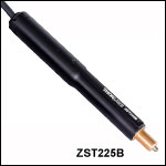
The ZST225B Actuator provides smooth, precise linear motion control in a package measuring 150.5 mm (5.93") in length. Powered by a small-diameter, dual-phase stepper motor, this actuator operates at speeds of up to 2.0 mm/s. The non-rotating drive tip reduces wear and friction and improves smoothness of motion by removing rotational contact at the tip. Mounting is via a standard Ø3/8" (Ø9.525 mm) barrel.
This actuator uses a stepper motor that provides sufficient torque for loads up to 40 N (8.99 lb). It allows very small step sizes over the entire travel range, delivering greater flexibility with low (<15 µm) backlash and fine resolution. The design incorporates a 41:1 gear reduction head which, when combined with the 49 152 microsteps per revolution offered by the KST201 stepper motor driver, gives a theoretical travel per microstep of 0.5 nm (see the Calculations tab for details).
Hall effect limit switches prevent the unit from being overdriven and provide homing capability with an accuracy of <5.0 μm. The ZST225B ships with 0.6 m (2 ft) of cable terminated in a 15-pin D-Type connector that is compatible with our KST201 stepper motor controller. A 1 m (3.3 ft) extension cable (PAA614) is available separately.
The ZST225B has a standard Ø3/8" (Ø9.525 mm) mounting barrel for fastening into any application compatible with our precision micrometer heads, like the PT1 Single-Axis Translation Stage or the PT3 Three-Axis Translation Stage.
Required Controller:
KST201
- 49 152 Microsteps per Revolution
- 15 V Output at 12 W
- Trapezoidal and
'S-Curve' Velocity Profiles

Click for Details
An LNR25 1" travel stage shown with the manual adjuster replaced by a ZST225B actuator.

| Key Specificationsa | |
|---|---|
| Travel Range | 25 mm (0.98") |
| Unidirectional Repeatability | ±1.6 µm |
| Bidirectional Repeatability | ±3.9 µm |
| Maximum Pushing Forceb | 180 N |
| Maximum Velocity | 50 mm/s |
| Maximum Acceleration | 50 mm/s2 |
| Limit Switches | Hall Effect |
| Homing Repeatability | ±3.6 µm |
| Feedback | Nonec |
| Motor Type | 2-Phase Stepper Motor |
| Full Step Angle | 1.8° |
| Lead Screw Pitch | 1.0 mm |
| Microsteps per Revolution | 409 600 |
| Actuator Mass | 0.58 kg |
| Compatible Controllersd | BSC201, BSC202, BSC203, or MST602 |
- Compatible with LNR50 TravelMax™ Stages
- ±1.6 µm Unidirectional Repeatability
- Maximum Pushing Force: 180 N
- Preload to Eliminate Backlash
- Non-Rotating Tip
- 50 mm Travel Version Also Available
The DRV225 Trapezoidal Stepper Motor Drive offers 25 mm (0.98") of travel and a unidirectional repeatability of ±1.6 μm. When used with one of our stepper motor controllers, this actuator can achieve a theoretical minimum step size of 2.4 nm and a maximum speed of 50 mm/s.
The hybrid stepper motor, with its rotor that consists of 50 individual magnetic teeth, is ideally suited for microstepping applications. Its 200 full steps per revolution are further broken down into 409 600 microsteps. In addition to the resulting increase in resolution, microstepping produces smoother low-speed motion by allowing the discrete 1.8° step size to be reduced to much smaller steps with inherently lower vibrational noise.
The DRV225 stepper motor drive is equipped with a trapezoidal screw thread for more efficient high-load operation than is available from standard threading.
This actuator is compatible with our 2" TravelMax manual stages. To use the DRV225 with these stages, mount the motor to the side of the stage using two 40 mm long M4 cap screws (included).
A 500 mm (19.7") cable with a 15-pin D-type connector is attached to the unit to connect the stepper motor to a controller. The unit also comes with a 3 m (9.8 ft) extension cable (item # PAA613). If a shorter cable is needed, the 1 m (3.3 ft) PAA612 cable is available separately.
Recommended Controllers:
BSC201, BSC202, or BSC203
- 409 600 Microsteps per Revolution
- 48 V Output at 25 W
- Trapezoidal and
'S-Curve' Velocity Profiles
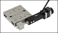
Click for Details
An LNR50 Series 2" Travel Stage with the Manual Adjuster Replaced by a DRV225 Actuator

| Item # | Z925B |
|---|---|
| Travel Range | 25 mm (0.98") |
| Encoder Resolutiona | 34 555 counts/mm (Linear Displacement) |
| Maximum Pushing Force | 45 N |
| Homing Repeatability | ±9 µm |
| Uncompensated Backlash | 13 µm |
| Uncompensated Bidirectional Repeatability | ±7 µm |
| Residual Backlash After Compensationb | 0.7 µm |
| Compensated Bidirectional Repeatability | ±0.8 µm |
| Travel Accuracyc | 40 µm |
| Minimum Repeatable Incremental Movement | 0.2 µm |
| Maximum Speedd | 2.6 mm/s |
| Maximum Acceleration | 4 mm/s2 |
| Phase to Phase Resistance | 33.0 Ω |
| Phase to Phase Inductance | 0.6 mH |
| Tested Lifetimee | > 100 000 In and Out Cycles |
| Operating Temperature Range | 41° to 104° F (5° to 40° C) |
| Weight | 0.13 kg |
| Motor Type | DC Servo |
| Cable Length | 485.0 mm (19.09") |
| Required Controller | KDC101 |
- 6 VDCサーボアクチュエータ
- サブマイクロメートルの分解能
- 最高速度:2.6 mm/s
- 移動量25 mmの様々な手動アクチュエータの代わりに取付け可能
- Ø3/8インチ(Ø9.525 mm)バレル付きステージやマウントに対応
- リミットスイッチ付き(ゼロ点とアクチュエータ保護用)
- 移動量6 mmと12 mmの製品もご用意
電動アクチュエータZ9シリーズは、光学的な位置決め装置と組み合わせて使用するように設計されています。 これらの製品は軽量なパッケージながら高分解能であるため、要求の厳しい光学実験システムを自動化するためのデバイスとして適しています。Z925Bの移動距離は25 mmです。
市販のリミットスイッチが取付けられており、これでオーバードライブの防止と精密なホーム位置決めを行います。内蔵されているモータは最大速度2.6 mm/sまで動作しますが、仕様の制御性能を得るために最大速度を2.3 mm/s以下に制限して駆動することをお勧めします。精密なエンコーダ(512カウント/回転)が使用されているため、最小分解能として約29 nmが得られます(詳細は「計算」タブをご参照ください)。
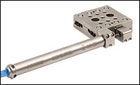
Z925Bは、単軸移動ステージPT1/Mや3軸移動ステージPT3/MのようなØ3/8インチ(Ø9.525 mm)バレルクランプ付きのステージやミラーマウントに取り付けられている手動アジャスタを代替できる製品として設計されています。
取り付けるときは、既存の手動アジャスタをマウントから取り外してから、Z9アクチュエータを取り付けてください。下の写真の3軸ステージPT3(/M)の1つの軸にはZ925Bが取り付けられています。
ユニットには長さ485.0 mmのケーブルが付いています。長さ2.5 mのエクステンションケーブルPAA632を別途ご購入いただくこともできます。
必要な移動量が異なる場合には、移動量6 mmのZ906や移動量12 mmのZ912アクチュエータをご覧ください。当社では10-6 Torrまでの真空圧力に対応するZ825BVもご提供しています(下記参照)。この製品には485.0 mmのリボンケーブル、IDCコネクタ、コントローラKDC101用コンバーターケーブルが付属しています。
DCサーボコントローラKDC101は、Z9シリーズのアクチュエータを駆動するのに必要なドライバです。最新のKinesisソフトウェアはこちらからダウンロードいただけます。KDC101をZ9シリーズアクチュエータと組み合わせてご使用いただくには、バージョン2.2.8以上のファームウェアが必要です(バージョン1.14.40以上のKinesisソフトウェアをダウンロードしていただくと付属しています)。旧バージョンのファームウェアでもZ9シリーズを駆動できますが、その場合、アクチュエータはZ8と呼ばれます。
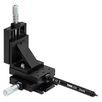
Click to Enlarge
手動アジャスタの代わりにDCサーボモーターアクチュエータZ925Bが取り付けられた移動量25 mmのXYZ移動ステージ

| Item # | Z925BV |
|---|---|
| Travel Range | 25 mm (0.98") |
| Encoder Resolutiona | 34 555 counts/mm (Linear Displacement) |
| Maximum Pushing Force | 45 N |
| Homing Repeatability | ±9 µm |
| Uncompensated Backlash | 13 µm |
| Uncompensated Bidirectional Repeatability | ±7 µm |
| Residual Backlash After Compensationb | 0.7 µm |
| Compensated Bidirectional Repeatability | ±0.8 µm |
| Travel Accuracyc | 40 µm |
| Minimum Repeatable Incremental Movement | 0.2 µm |
| Maximum Speedd | 2.6 mm/s |
| Maximum Acceleration | 4 mm/s2 |
| Maximum Phase to Phase Resistance | 33.0 Ω |
| Maximum Phase to Phase Inductance | 0.6 mH |
| Tested Lifetimee | > 100,000 In and Out Cycles |
| Operating Temperature Range | 41° to 104° F (5° to 40° C) |
| Vacuum Rating | 10-6 Torr |
| Weight | 0.094 kg |
| Motor Typef | DC Servo |
| Cable Length | 485.0 mm (19.09") |
| Required Controller | KDC101 |
- DCサーボアクチュエータ
- サブマイクロメートルの分解能
- 最大動作速度:2.6 mm/s
- 移動量25 mmの様々な手動アクチュエータの代わりに取付け可能
- Ø3/8インチ(Ø9.525 mm)バレル接続部の付いたステージやマウントに取付け可能
- リミットスイッチ付き(ゼロ点とアクチュエータ保護用)
- 10-6 Torrまでの真空圧力に対応
- 移動量6 mmと12 mmの製品もご用意
アクチュエータZ925BVは、アクチュエータZ925Bと同様の特長と仕様を有しますが、さらに10-6 Torrまでの真空圧力下でご使用いただくことができます。真空対応のサーボモータ、リン青銅製の内部カップリング機構や取付けブッシュ、高真空用グリースなどが使用されています。
このアクチュエータには、IDCコネクタの付いた、長さ485.0 mmの真空対応フラットリボンケーブルが付属しています。コントローラKDC101用のコンバーターケーブルも付属していますが、真空対応ではないため、チャンバの外でのみご使用ください。
Z925BVは、1軸移動ステージPT1/Mや3軸移動ステージPT3/Mのような、Ø3/8インチ(Ø9.525 mm)バレルクランプ付きのステージやミラーマウントの手動アジャスタを代替できる製品として設計されています。
取り付けるときは、既存の手動アジャスタをマウントから取り外してから、Z9アクチュエータを取り付けてください。下の写真では、カスタム仕様の真空対応ステージLNR25M(/M)にアクチュエータZ825BVが取り付けられています。真空対応のステージについてのご質問等は当社までお問い合わせください。移動量の異なる製品が必要な場合は、移動量6 mmのアクチュエータZ906Vや、移動量12 mmのアクチュエータZ912VおよびZ912BVをご覧ください。
DCサーボコントローラKDC101は、Z9シリーズのアクチュエータを駆動するのに必要なドライバです。最新のKinesisソフトウェアはこちらからダウンロードいただけます。KDC101をZ9シリーズの真空対応アクチュエータに使用するには、ファームウェアバージョンは2.2.8以降、Kinesisソフトウェアバージョンは1.14.44以降であることが必要です。

| Item #a | PIA25 | |||
|---|---|---|---|---|
| Travel | 25 mm (0.98") | |||
| Step Sizeb,c | 10 - 30 nm (Typ.) ≤ 30 nm (Max) | |||
| Step Size Adjustabilityd | ≤30% | |||
| Max Step Frequency | 2 kHz | |||
| Backlash | None | |||
| Max Active Preloade | 25 N | |||
| Recommended Max Axial Load Capacityf | 2.5 kg (5.5 lbs) | |||
| Speed (Continuous Stepping)b,c | 1.2 - 3.6 mm/min (Typ.) ≤ 3.6 mm/min (Max) | |||
| Drive Screw | 1/4"-80 Thread, Hard PVD Coated | |||
| Motor Type | Piezoelectric Inertia | |||
| Mounting Feature | Ø3/8" (Ø9.525 mm) Barrel | |||
| Operating Temperature | 10 to 40 °C (50 to 104 °F) | |||
| Dimensions | 2.81" x 1.24" x 0.67" (71.4 mm x 31.5 mm x 17.0 mm) | |||
| Cable Length | 1.0 m (3.28') | |||
| Connector | SMC, Female | |||
| Required Controllerg | KIM001 or KIM101 | |||
- 移動ステージに取付け可能なØ3/8インチ(Ø9.525 mm)バレル
- 31.5 mm x 17.0 mm(W x H)の小型設計
- アジャスターネジのノブで手動調整が可能
- 最大動作電圧:125 V
- 移動量13 mmおよび50 mmの製品もご用意
- 高分解能での相対位置決めとその保持が求められる用途に適した製品
- 制御ケーブルの角度は、最大110°まで調節可能
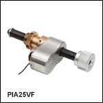
ピエゾ慣性アクチュエータPIA25は、コンパクトなパッケージながらピエゾ制御により長い距離を高分解能で直線移動することができます。最大荷重は2.5 kgまで、最大予備荷重は25 Nまでの範囲で10 nm~30 nmの典型的なステップサイズが得られ、またバックラッシュも生じません。このステップサイズは、コントローラKIM101およびKinesis®ソフトウェアを用いて、約30 nmまでの範囲内で最大30%の調整が可能です。しかし開ループであるため、ピエゾのヒステリシスや動作方向などの使用条件によって、システムのステップサイズは最大20%程度変化する可能性があり、また一般に再現性もありません。この変動を除去するには外部フィードバックシステムが必要です。
アクチュエータにはØ3/8インチ(Ø9.525 mm)バレルが付いているため、Ø3/8インチ(Ø9.525 mm)の取付け用クランプが付いたすべての手動ステージに取り付けられます。1/4"-80または3/16"-100 ネジ付きミラーマウントに対応する製品としては、移動量10 mmのピエゾ慣性アクチュエータをご覧ください。このアクチュエータは、システム静止時やピエゾ素子に電源が供給されていない時には自動的にロックされるため、ナノメートルレベルの分解能とアライメントの長期安定性が必要とされる用途に適しています。ピエゾアクチュエータを用いてアクティブにネジを移動させていないときは、アジャスターネジのノブを用いて手動調整が可能です。ノブは2.0 mm六角レンチでも操作できます。
長さ10 mmの多段チップ型ピエゾアクチュエータにより、このアクチュエータは最大速度3.6 mm/minで動作します。このピエゾモータは、移動中は送りネジの先端を回転させるように設計されています。ピエゾ慣性アクチュエータを用いた「スリップスティック」モータの設計については、こちらをご覧ください。
必要なコントローラ
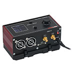
ピエゾ慣性アクチュエータPIA25を駆動するには、コントローラKIM001またはKIM101が必要です。標準的なピエゾコントローラでは、このアクチュエータを駆動することはできません。これらのドライバには鋸歯状波形の電圧信号発生器が内蔵されており、85 V~125 Vの範囲で振幅調整の可能なサブミリ秒のパルス(ステップ)を出力できます。コントローラKIM001はシングルチャンネル出力、KIM101は4チャンネル出力です。
詳細はこちらの製品紹介ページをご参照ください。
必要なコントローラ:
KIM001またはKIM101
- KIM001: シングルチャンネル出力
- KIM101: 4チャンネル出力、多チャンネルの操作が可能
- 上面パネルによる単体での操作、またはUSB経由のPC制御が可能
- 出力電圧:85 V~125 V
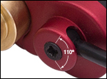
Click for Details
スペースが限られている用途向けに制御用ケーブルの角度を最大110°まで調節可能

| Item #a | PIA25VF |
|---|---|
| Travel | 25 mm (0.98") |
| Step Sizeb,c | 10 - 30 nm (Typ.) ≤30 nm (Max) |
| Step Size Adjustabilityd | Up to 30% |
| Max Step Frequency | 2 kHz |
| Backlash | None |
| Max Active Preloade | 25 N |
| Recommended Max Axial Load Capacityf | 2.5 kg (5.5 lbs) |
| Speed (Continuous Stepping)b,c | 1.2 - 3.6 mm/min (Typ.) ≤3.6 mm/min (Max) |
| Drive Screw | 1/4"-80 Thread, Hard PVD Coated |
| Motor Type | Piezoelectric Inertia |
| Mounting Featureg (Auxiliary) | Ø3/8" (Ø9.525 mm) Barrel (3/8"-40 Thread with Lock Nut) |
| Vacuum Rating | 10-6 Torr |
| Operating Temperature | 5 to 40 °C |
| Max Bakeout Temperature | 130 °C |
| Dimensions | 72.0 mm x 31.5 mm x 17.0 mm (2.83" x 1.24" x 0.67") |
| Mass (Including Cable) | 60 g (2.12 oz) |
| Cable Length | 0.75 m (2.46 ft) Flying Lead for Vacuum, 1.0 m (3.3 ft) Cored Cable for Wiring Outside Chamber |
| Connector | SMC Female |
| Required Controllerh | KIM001 or KIM101 |
- 31.5 mm x 17.0 mm(W x H)の小型設計
- 20 nmのステップサイズ(典型値)
- アジャスターネジのノブで手動調整が可能
- 10-6 Torrまでの真空圧力に対応
- 最大動作電圧:125 V
- 移動ステージに取付け可能なØ3/8インチ(Ø9.525 mm)バレル
- 高分解能での相対位置決めとその保持が求められる用途に適した製品
- 移動量13 mmおよび50 mmの製品もご用意
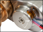
Click for Details
スペースが限られている用途向けにリード線の角度は最大110°まで調節可能
真空対応ピエゾ慣性アクチュエータPIA25VFは10-6 Torrまでの真空圧力に対応しており、またコンパクトな真空対応パッケージながらピエゾ制御により長い距離を高分解能で直線移動することができます。最大荷重は2.5 kgまで、最大予備荷重は25 Nまでの範囲で10 nm~30 nmの典型的なステップサイズが得られ、またバックラッシュも生じません。このステップサイズは、コントローラKIM101およびKinesis® ソフトウェアを用いて、約30 nmまでの範囲内で最大30%の調整が可能です。しかし開ループであるため、ピエゾのヒステリシスや動作方向などの使用条件によって、システムのステップサイズは最大20%程度変化する可能性があり、また一般に再現性もありません。この変動を除去するには外部フィードバックシステムが必要です。
アクチュエータにはØ3/8インチ(Ø9.525 mm)バレルが付いているため、Ø3/8インチ(Ø9.525 mm)の取付け用クランプが付いたすべての手動式移動ステージに取り付けられます。1/4"-100ネジ付きミラーマウントに対応する製品としては、移動量10 mmのピエゾ慣性アクチュエータがございます。このアクチュエータは、システム静止時やピエゾ素子に電源が供給されていない時には自動的にロックされるため、ナノメートルレベルの分解能とアライメントの長期安定性が必要とされる用途に適しています。ピエゾアクチュエータを用いてアクティブにネジを移動させていないときは、アジャスターネジのノブを用いて手動調整が可能です。ノブは2.0 mm六角レンチでも操作できます。
アクチュエータには長さ0.75 mのリード線が付いており、そのほかに真空チャンバの外での接続用に長さ1.0 mのケーブルが付属しています。このリード線とケーブルは必要に応じて切断可能ですが、真空槽の内外を合わせた全長は2.0 mを超えないようにしてください。上の写真のようにアクチュエータのリード線は最大110°まで回転できます。これはスペースの限られた場所で有用です。
長さ10 mmの多段チップ型ピエゾアクチュエータにより、このアクチュエータは最大速度3.6 mm/minで動作します。このピエゾモータは、移動中は送りネジの先端を回転させるように設計されています。ピエゾ慣性アクチュエータを用いた「スリップスティック」モータの設計については、こちらをご覧ください。
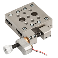
Click to Enlarge
移動ステージLNR25M/Mのマイクロメータの代わりに取り付けられたピエゾ慣性アクチュエータPIA25VF(真空対応のステージのご注文については、当社までお問合せください)。
必要なコントローラ
ピエゾ慣性アクチュエータPIA25VFを駆動するには、コントローラKIM001またはKIM101が必要です。標準的なピエゾコントローラでは、このアクチュエータを駆動することはできません。これらのドライバには鋸歯状波形の電圧信号発生器が内蔵されており、85 V~125 Vの範囲で振幅調整の可能なサブミリ秒のパルス(ステップ)を出力できます。コントローラKIM001はシングルチャンネル出力、KIM101は4チャンネル出力です。
詳細はこちらの製品紹介ページをご参照ください。
必要なコントローラ:
KIM001またはKIM101
- KIM001: シングルチャンネル出力
- KIM101: 4チャンネル出力、多チャンネルの操作が可能
- 上面パネルによる単体での操作、またはUSB経由のPC制御が可能
- 出力電圧:85 V~125 V

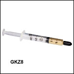
- 注入器入りApiezon 100グリース、1.5 cc入り
- 便利でムダのない低価格パッケージ
- アクチュエータの寿命を延長
- 注入しやすい容器入り
- 10-9 Torrまでの真空に対応
この Apiezonグリースは、優れた焼き付き防止特性を備えています。このグリースには潤滑性を高めるための PTFEが含まれていて、当社のZST、ZFS、Z9シリーズのアクチュエータの親ネジを再潤滑するのに適しています。 この製品は使いやすい注入器入りで、汎用および10-9 Torrまでの真空用途の両方にお使いいただけます。適する動作温度は 10 ~30 °Cです。
注: Z9、ZFSおよびZSTシリーズのモータの親ネジは10,000サイクルまたは 6か月ごとに潤滑油を差すことをお勧めします。

DRV、ZSTおよびZFSシリーズのステッピングモーターアクチュエータと、Z9シリーズのDCサーボモーターアクチュエータには、必要なコントローラとの接続用ケーブルが付いています。これらのケーブルのエクステンション用としてご使用いただけるケーブルも、別途ご用意しています。
ステッピングモータ用ケーブル
当社ではステッピングモーターアクチュエータとコントローラを接続するための様々なケーブルをご用意しております。ZST、ZFSおよびDRVシリーズのステッピングモーターアクチュエータと、BSCシリーズのベンチトップ型コントローラ、K-Cube™コントローラKST201、およびラック型制御モジュールMST602との間の接続をサポートしています。ステッピングモータとコントローラの組み合わせに対して使用可能なケーブルは、下の表をご参照ください。各ケーブルのピン配列については、こちらの製品紹介ページをご覧ください これらのケーブルはコネクタが同じであっても、ピン配列が適合しないモータとコントローラにはお使いいただけませんのでご注意ください。
DCモータ用ケーブル
PAA632はZ9シリーズのDCモーターアクチュエータ用のケーブル(長さ2.5 m)です。このケーブルはK-Cube DCサーボモーターコントローラKDC101との接続用として作られています。このケーブルのピン配置はこちらの製品紹介ページをご覧ください。 15ピンコネクタが使われていますが、当社のステッピングモータには対応しておりません。

 |
|
 Products Home


 ズーム
ズーム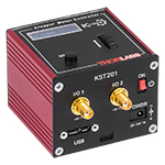


 移動量25 mm