Cシリーズ サーマルパワーセンサー
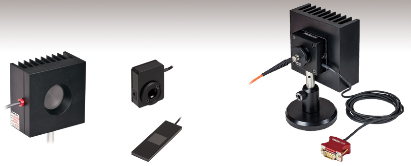
- Power Ranges Covering 10 µW to 200 W
- Wavelength Ranges Covering 190 nm to 20 µm
- Broadband Coatings with High Damage Thresholds
- Sensors Designed for Microscopes and Pulsed Lasers
S425C-L
Featuring Removable
Heat Sink and Shown
with a Fiber Adapter
(Sold Below) and
Fiber Patch Cable
S350C
For Excimer Lasers
S401C
High Sensitivity
Down to 10 µW
S175C
18 mm x 18 mm Aperture Size
for Use with Microscopes

Please Wait
S405Cの開口に付いているSM05内ネジ(写真左)には、付属のSM05 -SM1ネジ変換アダプタを取り付けることができます(写真右)。多くのセンサには、ファイバーアダプタなどのアクセサリを取り付けることができるSM1外ネジ付きアダプタが付属します。
Click to Enlarge
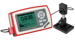
コンソールPM100Dに接続されたS401C。
| Power Meter Selection Guide |
|---|
| Sensors |
| Photodiode Power Sensors |
| Thermal Power Sensors |
| Thermal Position & Power Sensors |
| Pyroelectric Energy Sensors |
| Power Meter Consoles and Interfaces |
| Digital Handheld Console |
| Analog Handheld Console |
| Touchscreen Handheld Console |
| Dual-Channel Benchtop Console |
| USB Interfaces with External Readout |
| Complete Power Meters |
| Power Meter Bundles |
| Wireless Power Meters with Sensors |
| Compact USB Power Meters |
| Field Power Meters for Terminated Fibers |
特長
- 広い波長範囲で比較的平坦なスペクトル応答特性(下記プロット図を参照)
- 全品校正済み、NISTおよびPTBにトレーサブルなCertificate of Calibration(校正証明書)付き
- 自由空間およびファイバに対応
- すべてのセンサが自由空間入力に対応
- 多くのセンサはファイバ入力用ファイバーアダプタ(下記参照)の取付けが可能
- Cシリーズコネクタ
- 当社のパワーメーターコンソールへの接続が簡単
- 内蔵のEEPROMにはセンサ情報と校正データが保存
- 高温度警告センサ付きのモデルは10種類(詳細は「仕様」タブをご参照ください)
当社のCシリーズのサーマルパワーセンサでは、波長範囲190 nm~20 µmで 10 µW ~200 Wのパワーを検出できる製品を取り揃えています。これらのセンサはサーモパイル型で、自然放射増幅光(ASE)、発光ダイオード(LED)、白熱電球、波長掃引レーザなどの広帯域スペクトル光源の測定にお使いいただけます。また、サーマルパワーセンサは飽和しないので、高いピークパワーや長いパルス幅を有するパルス光源の測定にも適しています。サーマルパワーセンサは入射光の角度や位置に対する依存性も大きくありません。これは、フォトダイオードセンサの顕著な波長依存性や飽和閾値を許容できない用途には望ましい特性ですが、一般にサーマルパワーセンサのパワー分解能はフォトダイオードよりも低く、応答時間は長くなります。当社では、異なる特長をもつサーマルパワーセンサを幅広くご用意しています。
取付け
このページでご紹介しているセンサ(S175Cを除く)はM4(多くは#8-32も使用可)もしくはM6タップ穴を使用して、当社のØ12 mm~Ø12.7 mm(Ø1/2インチ)ポストに取付け可能です。 一部のセンサには高さ60 mmもしくは75 mmのポストが付属しています。また、センサの多くは30 mmケージシステム、Ø25 mm~Ø25.4 mm(1インチ)レンズチューブシステム 、ファイバーアダプタ(下記参照)にも対応しています。詳細については、「仕様」タブをご参照下さい。
校正
個々のセンサーヘッドはすべて校正されており、NISTおよびPTBにトレーサブルな校正証明書と一緒に出荷されます。校正や識別に関するデータはセンサのコネクタに内蔵されたEEPROMに保存されており、接続されたパワーメーターコンソールに自動的にダウンロードされます。このEEPROMには、センサのモデル名やシリアル番号、波長範囲、内蔵のサーミスタの情報(該当製品のみ)、校正日も記録されています。センサの校正については、当社のパワーメータ&センサのチュートリアルのページの「校正」タブをご覧ください。
対応するパワーメータ
センサは全てCシリーズコネクタを介してパワーメーターコンソールに接続されるので、センサの交換は簡単に行えます。これらのセンサは当社が現在販売しているパワーメーターコンソールに対応していますが、旧タイプのコンソールには対応しておりません。 センサの応答時間が1秒よりも大きい場合は、パワーメータはコネクタに保存されたデータを利用して「センサ時定数」で定義される時間経過後の入力パワーを予測できます。詳細については「動作」タブをご覧ください。
再校正サービス
当社では再校正サービスを提供しております。センサ精度維持および測定値の検証のために、定期的な再校正をお勧めしています。校正頻度はご用途にもよりますが、通常1年程度です。再校正の詳細や価格などにつきましては、当社までお問い合わせください。
センサのアップグレードサービス
全てのCシリーズのセンサは、Cシリーズのコネクタが付いていない旧タイプのパワーメーターコンソールに対応しておりません。当社では、お手持ちのセンサを新しいCシリーズコネクタ付きパワーメーターコンソールと組み合わせてお使いいただけるよう、アップグレードサービスを提供しております。尚、 アップグレード後は、Cシリーズのコネクタが付かない旧タイプのパワーメーターコンソールとはお使いいただけませんのでご注意ください。詳細は当社までお問い合わせください。
| Thermal Power Sensors Selection Guide | |||||
|---|---|---|---|---|---|
| Type | High Resolution | Max Power: 10 W | Max Power: 40 W to 200 W | High Max Power Density for Pulsed Lasers | Microscope Slide Thermal Sensor |
| Wavelength Rangea | 190 nm - 20 µm | 190 nm - 20 µm | 190 nm - 20 µm | 250 nm - 10.6 µm | 300 nm - 10.6 µm |
| Optical Power Rangea | 10 µW - 5 W | 2 mW - 10 W | 10 mW - 200 W | 100 µW - 10 W | 100 µW - 2 W |
| Max Optical Power Densitya | 500 - 1500 W/cm² (Avg.) | 1500 W/cm² (Avg.) | 2 - 4 kW/cm² (Avg.) | 35 W/cm² (Avg.); 100 GW/cm² (Peak, 1 ns Pulse) | 200 W/cm² |
| Resolutiona | 1 µW - 5 µW | 100 µW | 100 µW - 5 mW | 10 µW - 250 µW | 10 µW |
Cシリーズ サーマルパワーセンサ
下記のリンクをクリックいただくと対応する仕様表に移動します。
センサに関連する用語の定義についてはこちらをご覧ください。
高分解能
| Item # | S401C | S405C |
|---|---|---|
| Detection Specifications | ||
| Detector Type | Thermal Surface Absorber with Background Compensation (Axial Thermopile) | Thermal Surface Absorber (Axial Thermopile) |
| Wavelength Range | 190 nm - 20 µm | 190 nm - 20 µm |
| Optical Power Range | 10 µW - 1 W | 100 µW - 5 W |
| Max Average Power Densitya | 500 W/cm² | 1.5 kW/cm² |
| Max Pulse Energy Density | 0.2 J/cm² (1 µs Pulse), 2 J/cm² (1 ms Pulse) | 0.3 J/cm² (1 ns Pulse), 5 J/cm² (1 ms Pulse) |
| Max Intermittent Powerb | 3 W | - |
| Linearity | ±0.5% | ±0.5% |
| Resolutionc | 1 µW | 5 µW |
| Measurement Uncertaintyd (Calibration Uncertainty) | ±3% @ 1064 nm ±5% @ 190 nm - 10.6 µm | ±3% @ 1064 nm ±5% @ 250 nm - 17 µm |
| Response Timee | 1.1 s | 1.1 s |
| General Information | ||
| Suggested Application | Low Power Lasers and LEDs | Low Power Lasers and LEDs |
| Absorber | High-Power Broadband Coating | High-Power Broadband Coating |
| Cooling | Convection (Passive) | |
| Temperature Sensor (In Sensor Head) | NTC Thermistor | NTC Thermistor |
| Compatible Consoles | PM400, PM100D, PM100A, and PM5020 | |
| Compatible Interfaces | PM101, PM101A, PM101R, PM101U, PM102, PM102A, PM102U, and PM100USB | |
| Mechanical Specs | ||
| Housing Dimensions (Without Adapter) | 33.0 m x 43.0 mm x 15.0 mm (1.30" x 1.69" x 0.59") | 40.6 mm x 40.6 mm x 16.0 mm (1.60" x 1.60" x 0.63") |
| Sensor Input Aperture | Ø10 mm | Ø10 mm |
| Active Detector Area | 10 mm x 10 mm | 10 mm x 10 mm |
| Distance to Detectorf | 3 mm | 5 mm |
| Cable Length | 1.5 m | |
| Connector | D-Sub 9 Pin Male | |
| Weight | 0.05 kg (0.11 lb) | 0.11 kg (0.24 lb) |
| Mounting and Accessories | ||
| Post | Ø1/2" Post via Universal 8-32 & M4 Tap (Post Not Included) | Ø1/2" Post via Universal 8-32 & M4 Tap (Post Not Included) |
| Cage System Mounting | N/A | 30 mm Cage Systems via Two 4-40 Tapped Holes; Two Ø6 mm Through Holes for ER Series Rods |
| Aperture Thread | Internal SM05 | Internal SM05 |
| Accessories | Internally SM1-Threaded Adapter with an Internally SM05-Threaded Light Shield | Adapter with External SM05 and External SM1 Threads |
| Fiber Adapters (Available Below) | S120 Series Fiber Adapters | |
最大パワー: 10 W
| Item # | S415C | S425C |
|---|---|---|
| Detection Specifications | ||
| Detector Type | Thermal Surface Absorber (Axial Thermopile) | Thermal Surface Absorber (Axial Thermopile) |
| Wavelength Range | 190 nm - 20 µm | 190 nm - 20 µm |
| Optical Power Range | 2 mW - 10 W | 2 mW - 10 W |
| Max Average Power Densitya | 1.5 kW/cm² | 1.5 kW/cm² |
| Max Pulse Energy Density | 0.3 J/cm² (1 ns Pulse), 5 J/cm² (1 ms Pulse) | 0.3 J/cm² (1 ns Pulse), 5 J/cm² (1 ms Pulse) |
| Max Intermittent Powerb | 20 W | 20 W |
| Linearity | ±0.5% | ±0.5% |
| Resolutionc | 100 µW | 100 µW |
| Measurement Uncertaintyd (Calibration Uncertainty) | ±3% @ 1064 nm ±5% @ 250 nm - 17 µm | ±3% @ 1064 nm ±5% @ 250 nm - 17 µm |
| Response Timee | 0.6 s | 0.6 s |
| General Information | ||
| Suggested Application | Low and Mid-Power Lasers & LEDs | Low and Mid-Power Lasers & LEDs |
| Absorber | High-Power Broadband Coating | High-Power Broadband Coating |
| Cooling | Convection (Passive) | |
| Temperature Sensor (In Sensor Head) | NTC Thermistor | |
| Compatible Consoles | PM400, PM100D, PM100A, and PM5020 | |
| Compatible Interfaces | PM101, PM101A, PM101R, PM101U, PM102, PM102A, PM102U, and PM100USB | |
| Mechanical Specs | ||
| Housing Dimensions (Without Adapter) | 50.8 mm x 50.8 mm x 35.0 mm (2.00" x 2.00" x 1.38") | 50.8 mm x 50.8 mm x 35.0 mm (2.00" x 2.00" x 1.38") |
| Sensor Input Aperture | Ø15 mm | Ø25.4 mm |
| Active Detector Area | Ø15 mm | Ø27 mm |
| Distance to Detectorf | 5 mm | 4.6 mm |
| Cable Length | 1.5 m | |
| Connector | D-Sub 9-Pin Male | |
| Weight | 0.22 kg (0.49 lb) | 0.22 kg (0.49 lb) |
| Mounting and Accessories | ||
| Post | Ø1/2" Post via Universal 8-32 & M4 Tap (Post Not Included) | Ø1/2" Post via Universal 8-32 & M4 Tap (Post Not Included) |
| Cage System Mounting | N/A | N/A |
| Aperture Thread | Internally SM1-Threaded Aperture External SM1-Threaded Adapter for Ø1" Lens Tubes and Fiber Adapters | Internally SM1-Threaded (1.035"-40) with External SM1-Threaded Adapter for Ø1" Lens Tubes and Fiber Adapters |
| Fiber Adapters (Available Below) | S120 Series Fiber Adapters | |
最大パワー: 40 W~200 W
| Item # | S350C | S425C-L | S322C |
|---|---|---|---|
| Detection Specifications | |||
| Detector Type | Thermal Surface Absorber (Radial Thermopile) | Thermal Surface Absorber (Axial Thermopile) | Thermal Surface Absorber (Radial Thermopile) |
| Wavelength Range | 190 nm - 1.1 µm, 10.6 µm | 190 nm - 20 µm | 250 nm - 11 µm |
| Optical Power Range | 10 mW - 40 W | 2 mW - 50 W | 100 mW - 200 W |
| Max Average Power Densitya | 2 kW/cm² | 1.5 kW/cm² | 4 kW/cm² |
| Max Pulse Energy Density | 0.7 J/cm² (1 ns Pulse), 10 J/cm² (1 ms Pulse) | 0.3 J/cm² (1 ns Pulse), 5 J/cm² (1 ms Pulse) | 0.5 J/cm² (1 ns Pulse), 10 J/cm² (1 ms Pulse) |
| Max Intermittent Powerb (2 Minute Max) | 60 W | 75 W | 250 W |
| Linearity | ±1% | ±0.5% | ±1% |
| Resolutionc | 1 mW | 100 µW | 5 mW |
| Measurement Uncertaintyd (Calibration Uncertainty) | ±3% @ 1064 nm ±5% @ 190 nm - 1100 nm, 10.6 µm | ±3% @ 1064 nm ±5% @ 250 nm - 17 µm | ±3% @ 1064 nm ±5% @ 266 nm - 1064 nm |
| Response Timee | 9 s (1 s from 0 to 90%) | 0.6 s | 5 s (1 s from 0 to 90%) |
| General Information | |||
| Suggested Application | High-Power Excimer Lasers | Mid-Power Lasers | Mid-Power Lasers |
| Absorber | Excimer Coating | High-Power Broadband Coating | High-Power Broadband Coating |
| Cooling | Convection (Passive) | Forced Air with Fanef | |
| Temperature Sensor (In Sensor Head) | NTC Thermistor | ||
| Compatible Consoles | PM400, PM100D, PM100A, and PM5020 | ||
| Compatible Interfaces | PM101, PM101A, PM101R, PM101U, PM102, PM102A, PM102U, and PM100USB | ||
| Mechanical Specs | |||
| Housing Dimensions (Without Adapter, if Applicable) | 100 mm x 100 mm x 54.2 mm (3.94" x 3.94" x 2.13") | 100.0 mm x 100.0 mm x 58.0 mm (3.94" x 3.94" x 2.28") | 100 mm x 100 mm x 86.7 mm (3.94" x 3.94" x 3.41") |
| Sensor Input Aperture | Ø40 mm | Ø25.4 mm | Ø25 mm |
| Active Detector Area | Ø40 mm | Ø27 mm | Ø25 mm |
| Distance to Detectorg | 13 mm | 4.6 mm | 15 mm |
| Cable Length | 1.5 m | ||
| Connector | D-Sub 9-Pin Male | ||
| Weight | 1 kg (2.20 lb) | 0.71 kg (1.57 lb) | 0.75 kg (1.65 lb) |
| Mounting and Accessories | |||
| Post | M6, 75 mm Long Ø1/2" Post Included | Ø1/2" Post via Universal 8-32 & M4 Tap (Post Not Included) | M6, 75 mm Long Ø1/2" Post Included |
| Cage System Mounting | N/A | N/A | 30 mm Cage Systems via Four 4-40 Tapped Holes |
| Aperture Thread | Unthreaded | Internally SM1-Threaded Aperture with External SM1-Threaded Adapter for Ø1" Lens Tubes and Fiber Adapters | Externally SM1-Threaded Adapter for Ø1" Lens Tubes and Fiber Adapters |
| Fiber Adapters (Available Below) | S120 Series Fiber Adapters | ||
最大パワー密度の大きなパルスレーザ用
| Item # | S370C | S470C |
|---|---|---|
| Detection Specifications | ||
| Detector Type | Thermal Volume Absorber (Axial Thermopile) | Thermal Volume Absorber (Axial Thermopile) |
| Wavelength Range | 0.4 - 5.2 µm | 0.25 - 10.6 µm |
| Optical Power Range | 10 mW - 10 W | 100 µW - 5 W |
| Max Power Density | 35 W/cm² (Avg); 100 GW/cm² (Peak, 1 ns Pulse) | 35 W/cm² (Avg); 100 GW/cm² (Peak, 1 ns Pulse) |
| Max Pulse Energy Density | 1 J/cm² (1 ns pulse) 10 J/cm² (1 ms pulse) | 1 J/cm² (1 ns Pulse) |
| Max Intermittent Powera | 15 W | - |
| Linearity | ±1% | ±0.5% |
| Resolutionb | 250 µW | 10 µW |
| Measurement Uncertaintyc (Calibration Uncertainty) | ±3% @ 1064 nm ±5% @ 400 - 1064 nm | ±3% @ 1064 nm ±5% @ 250 nm - 10.6 µm |
| Response Timed | 45 s (3 s from 0 to 90%) | 6.5 s (<2 s="" from="" 0="" to="" 90="" td=""> |
| General Information | ||
| Suggested Application | High Peak Power Lasers | High Peak Power, Low Average Power Lasers |
| Absorber | Broadband Volume Absorber (Schott NG1 Filter) | Broadband Volume Absorber (Schott NG1 Filter) |
| Cooling | Convection | Convection |
| Temperature Sensor (In Sensor Head) | N/A | N/A |
| Compatible Consoles | PM400, PM100D, PM100A, and PM5020 | |
| Compatible Interfaces | PM101, PM101A, PM101R, PM101U, PM102, PM102A, PM102U, and PM100USB | |
| Mechanical Specs | ||
| Housing Dimensions (Without Adapter, if Applicable) | 75 mm x 75 mm x 51.2 mm (2.95" x 2.95" x 2.02") | 45.0 mm x 45.0 mm x 18.0 mm (1.77" x 1.77" x 0.71") |
| Input Aperture Size | Ø25 mm | Ø15 mm |
| Active Detector Areae | Ø25 mm | >Ø15 mm |
| Distance to Detectorf | 13 mm | 5.1 mm |
| Cable Length | 1.5 m | 1.5 m |
| Connector | Sub-D 9-Pin Male | Sub-D 9-Pin Male |
| Weight | 0.5 kg (1.10 lb) | 0.1 kg (0.22 lb) |
| Mounting and Accessories | ||
| Post | M6, 75 mm Long Post Included | Universal 8-32 / M4 Tap, Post Not Included |
| Cage System Mounting | 4 x 4-40 Threads for 30 mm Cage Compatibility | N/A |
| Aperture Thread | Externally SM1-Threaded Adapter for Ø1" Lens Tubes and Fiber Adapters | External SM1-Threaded Aperture for Ø1" Lens Tubes and Fiber Adapters |
| Fiber Adapters (Available Below) | S120 Series Fiber Adapters | S120 Series Fiber Adapters |
顕微鏡用スライドサーマルセンサ
| Item # | S175C |
|---|---|
| Detection Specifications | |
| Detector Type | Thermal Absorber (Axial Thermopile) |
| Wavelength Range | 0.3 - 10.6 µm |
| Optical Power Range | 100 µW - 2 W |
| Max Power Density | 200 W/cm2 |
| Max Pulse Energy Density | 0.1 J/cm² (1 µs pulse) 1 J/cm² (1 ms pulse) |
| Max Intermittent Power | - |
| Linearity | ±0.5% |
| Resolutiona | 10 µW |
| Measurement Uncertaintyb (Calibration Uncertainty) | ±3% @ 1064 nm ±5% @ 300 nm - 10.6 µm |
| Response Timec | 3 s (<2 s="" from="" 0="" to="" 90="" td=""> |
| General Information | |
| Suggested Application | Light Measurement on the Microscope Objective Plane |
| Absorber | Broadband Coating |
| Cooling | Convection |
| Temperature Sensor (In Sensor Head) | N/A |
| Compatible Consoles | PM400, PM100D, PM100A, and PM5020 |
| Compatible Interfaces | PM101, PM101A, PM101R, PM101U, PM102, PM102A, PM102U, and PM100USB |
| Mechanical Specs | |
| Housing Dimensions | 76 mm x 25.2 mm x 4.8 mm (2.99" x 0.99" x 0.19") |
| Input Aperture Size | 18 mm x 18 mm |
| Active Detector Area | 18 mm x 18 mm |
| Distance to Detectord | 1.1 mm |
| Cable Length | 1.5 m |
| Connector | Sub-D 9-Pin Male |
| Weight | 0.05 kg (0.11 lb) |
| Mounting and Accessories | |
| Post | N/A |
| Cage System Mounting | N/A |
| Aperture Thread | N/A |
| Fiber Adapters (Available Below) | N/A |
Cシリーズセンサーコネクタ
D型 オス
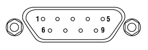
| Pin | Connection |
|---|---|
| 1 | Not Used |
| 2 | EEPROM Data |
| 3 | Sensor and NTC Ground |
| 4 | Not Used |
| 5 | Not Used |
| 6 | EEPROM Ground |
| 7 | NTC |
| 8 | Sensor Signal |
| 9 | Not Used |
動作原理
Click to Enlarge
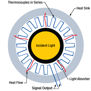
図1: 放射状に配列されたサーモカップルを内蔵するサーマルセンサ(図は上から見た様子)。光は中央の吸収層に入射し、熱はサーモカップルを通過してヒートシンクへと流れます。
Click to Enlarge
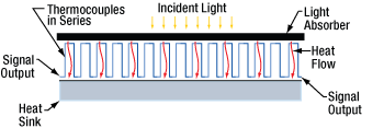
図2: 軸方向に配列されたサーモカップルを内蔵するサーマルセンサ(図は横から見た様子)。光は上部から入射し、熱はサーモカップルの層を通過して下方向に流れ、底面のヒートシンクで放熱されます。
当社のサーマルパワーセンサは、サーモパイル型です。センサの上層部は光を吸収する材料で構成されています。直列に接続された複数のサーモカップルが配置された領域は吸収体に近接しています。サーモカップルは異なる2種類の金属を接触させて作成されており、接触部はジャンクション(接点)と呼ばれています。サーモカップルの反対側にはヒートシンクがあります。サーモカップルは直列に接続されており、それぞれのジャンクションは吸収体とヒートシンクに交互に近接して配置されています。
吸収体は入射光のエネルギを熱に変換します。熱は吸収体からサーモカップルを通過してヒートシンクに流れ込み、そこで放熱されます。サーモカップルのジャンクションの温度は、吸収体の近くの方がヒートシンクの近くよりも高くなります。このジャンクションの配置は熱電(ゼーベック)効果をより良く利用するためのものです。熱電効果では隣接するジャンクション間に温度差に比例した電圧が発生します。複数のサーモカップルを直列に接続することで、発生する電圧は大きくなります。多くの場合、サーモカップルは図1のように放射状(radial、円盤状(disk)とも呼ばれます)、または図2のように軸方向(axial、格子状(matrix)とも呼ばれます)に配列されています。当社ではどちらの構成のサーマルパワーセンサもご提供しております。
放射状に配列されたサーモカップル
図1は、放射状に配列されたサーモパイルによるサーマルパワーセンサを上から見た様子です。この構造では光吸収体は中央に配置されています。光吸収体は、同心円状に並べられたサーモカップル(直列接続)に囲まれ、さらにサーモカップルは同心円のヒートシンクに囲まれています。吸収体に入射した光は熱に変換され、その熱はサーモカップルを通過してヒートシンクまで、動径方向に流れます。ヒートシンクは、サーモカップルのジャンクションの外輪部に機械的にぴったりと接触するように設計されており、光吸収体やサーモカップルの内輪部には熱的に接触しないようになっています。吸収体の裏側部分は他のものとの熱的接触を避け、熱の流れを意図した放射状の経路から逸らさないようにしなければなりません。
放射状配列の利点は、キロワットのパワーレベルまで測定できるセンサを設計できることです。この高い上限値は、センサーディスクの厚みと吸収体からサーモカップルまでの距離を適切に設定し、レーザによる熱衝撃からサーモカップルを保護することで実現されています。 一方、欠点は、特殊な設計のヒートシンクを使用しているためにセンサーヘッドのカスタマイズが複雑になることと、センサーヘッドの大きさが少なくとも検出部の直径の2倍はあることです。放射状配列のサーマルパワーセンサの分解能は、通常、10 mW程度に制限されます。
S350CおよびS322Cは放射状に配列されたサーマルパワーセンサで、中程度のパワー用に設計されています。
軸方向に配列されたサーモカップル
図2は、サーモカップルが軸方向に配列されたサーマルパワーセンサです。 図では、サーモカップルが2つの平らな層の間に配列されています。片方の層が光吸収体、もう一方の層がヒートシンクです。熱が正面から背面に直接流れるため、このセンサのパッケージはコンパクトにできます。センサ筐体は検出部とほぼ同じ大きさです。
新世代の軸方向配列のセンサは、マイクロワットの領域で比較的速い応答速度を保ちながら高い分解能を得ることができます。これらのセンサは数ワットまでの光パワーを検出できますが、この上限値は主に吸収体の厚みによって決まります。 S401CやS405Cのような新設計のセンサの性能は、応答時間の遅い旧世代の製品に比べて向上しています。
軸方向に配列されたサーモパイルのヒートシンクの形状および寸法は、放射状に配列されたサーモパイルに比べて制約が少なくなっています。軸方向配列のサーモパイルに使用するヒートシンクは、アルミニウムブロックを熱伝導性接着剤で取り付けたシンプルなものにも、あるいはセンサにはんだ付けされたメタルコアPCBのように洗練されたものにすることもできます。 サーマルパワーセンサS415C、S425C、S425C-Lのヒートシンクは簡単に取り外して交換できます。そのため、お客様側でヒートシンクにファンや水冷機能を付けてアップグレードしたり、センサをカスタムセットアップ内に組み込んだりすることができます。その際は、ヒートシンクが用途に適した放熱を行えるようにしてください。
パルスレーザ用の体積吸収体
表面吸収体の代わりに体積吸収体を使用すると、高エネルギのナノ秒の短パルスに晒されても耐えることができます。局所的なパルスエネルギを吸収すると損傷を受けてしまう表面吸収体と異なり、体積吸収体は入射光パルスによる熱を集め、体積全体に分散させます。吸収体全体で発生した熱はサーモカップルを通過して流れ、ヒートシンクで放熱されます。体積吸収体を使用したサーマルパワーセンサとしては、S370CとS470Cの2種類をご用意しています。どちらもNd:YAGレーザのパルスを検出するといった用途にご使用いただけます。これらの軸方向配列のセンサには、同タイプの他のセンサに付いている表面吸収体の代わりにSchott社製ガラスの体積吸収体が付いています。体積吸収体型センサの応答時間は、表面吸収体型センサに比べて遅くなりますが、これは体積吸収体のサーマルマスがより大きいためです。S470CはS370Cよりもガラスの体積が小さいうえに設計も異なるため、サーモパイルの応答時間は早くなっています。
Click to Enlarge
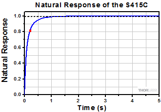
図3: S415Cの固有の応答特性。点線は99%のレベルを示し、曲線上の赤い四角はセンサの時定数に対応します。
固有の応答特性、センサ時定数およびパワーの予測測定
図3は、サーマルセンサS415Cへの入射光を暗い状態から一定強度の状態にステップ状に変化させたときの典型的な固有の応答特性です。このステップ関数的な入射光の変化に対する応答は指数関数でモデル化でき、コンデンサを充電する様子を表す関数に類似します。
センサ時定数は、センサの応答が最大応答の99%に達するのにかかる時間を用いて定義されます。センサが99%のレベルに達したとき、センサ時定数の5倍に等しい時間が経過したものとします。図3において、点線は99%のレベルに対応し、赤い四角はセンサ時定数で定義される時間が経過したときの応答に対応しています。
センサの固有の応答特性の関数がわかっている場合、それをモデルとして使用し、センサの読取値が安定な一定値を示す前に最終的なパワー読取値を予測することができます。当社のパワーメーターコンソールでは、時定数が0.5秒以上(固有の応答時間>1秒)のセンサを接続した場合、安定になった状態のパワー読取値を算出し、その予測値を表示することができます。予測は、Cシリーズコネクタに内蔵されたEEPROMに保存されているセンサの情報を用いて行われます。 S415C、S425CおよびS425C-Lのセンサ時定数は0.2秒未満(固有の応答時間は0.6秒未満)と十分早いので予測は必要なく、実施することはできません。他のセンサでは予測を行うことができます。
予測機能がアクティブ化されている時、1回目の予測はセンサ時定数に等しい時間経過後に実施され、その後はセンサ時定数の時間間隔で7回まで予測値が更新されます。その後、予測機能はオフになります。センサ時定数の7回分の時間が経過した後のパワー読取値は最終読取値の99.9%以内になります。測定値の予測には不確実性が伴うため、リップルが出現する場合があります。センサの速度が早いほど、この不確実性は低減します。予測機能がオフになった後、パワー読取値の勾配がモニタされ、定義された閾値を超える値の増加が検知されると、再度予測が可能になります。
熱的外乱からのサーマルパワーセンサの保護
正確な測定結果を得るには、動作中のサーマルパワーセンサは空気の流れや熱的外乱から保護する必要があります。さもないと測定値がドリフトしてしまいます。これは高い分解能を有する低パワー用センサで特に重要です。サーマルパワーセンサを手で持って操作すると、体温がセンサやヒートシンクに伝わり、測定結果の精度に悪影響を及ぼす可能性があるため、お勧めいたしません。
サーマルパワーセンサは温度差を電圧信号に変換して測定します。センサは、吸収体内部で発生した熱が確実にヒートシンクに流れ込むことを想定して設計されています。動作中にセンサ筐体に触れると、体温がセンサに伝わり、パワーの測定結果が不正確になる可能性があります。例えば、センサのヒートシンクを持った場合、手からヒートシンクに伝わった熱が吸収体に流れ込んでしまいます。その場合、もし吸収体に光が入射していなければ、マイナスのパワー値が表示されます。もし吸収体に光が入射していれば、不正確なパワー値が表示されます。
当社では、幅広いパワーメータ&エネルギーメータ用コンソールやパワーセンサ・エネルギーセンサを操作するためのインターフェイスを取り揃えています。 主な仕様は下記でご覧いただけるので、お客様の用途に適したモデルをお選びいただけます。 下記のほかに、センサ内蔵のワイヤレスパワーメータや小型USBパワーメータもご用意しております。
当社のパワーメータ等用のコンソールやインターフェイスは、Cシリーズのセンサとお使いいただく場合は接続したセンサの種類を自動的に認識し、電流値とそれに応じた電圧値を測定します。 Cシリーズのセンサは、コネクタ内に感度特性の校正データが保存されています。 コンソールは、入射波長に対応する感度の値を読み出し、パワーもしくはエネルギの測定値を計算します。
- フォトダイオードセンサは、入射光の光パワーと波長によって決まる電流を流します。 この電流は、トランスインピーダンスアンプに送られ、このアンプから入力電流に比例した電圧が出力されます。 フォトダイオードの感度は波長に依存するため、正確なパワーの測定値を得るためには、コンソールに正しい波長を入力する必要があります。 コンソールは、接続されたセンサから、入力された波長における感度を読み取り、測定した光電流から光パワーを計算します。
- サーマルセンサは、入射された光パワーに比例した電圧を送ります。 測定されたセンサの出力電圧とその感度特性に基づいて、コンソールは入射した光パワーを計算します。
- エネルギーセンサは焦電効果に基づいています。 したがって、エネルギーセンサは、パルスエネルギに比例したピーク電圧を送ります。 エネルギーセンサが認識されると、コンソールはピーク電圧ディテクタを活用し、センサの感度特性からパルスエネルギが計算されます。
コンソールやインターフェイスはセンサが出力する電流や電圧を表示する機能も備えています。 または、測定された電流や電圧をアナログ出力で得ることもできます。
コンソール
| Item # | PM100A | PM100D | PM400 | PM5020 |
|---|---|---|---|---|
| (Click Photo to Enlarge) | 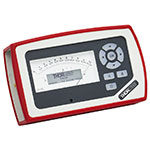 | 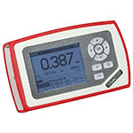 | 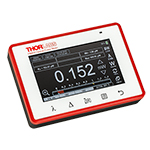 | 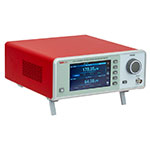 |
| Key Features | Analog Power Measurements | Digital Power and Energy Measurements | Digital Power and Energy Measurements, Touchscreen Control | Dual Channel |
| Compatible Sensors | Photodiode and Thermal Power | Photodiode Power, Thermal Power, and Pyroelectric Energya | Photodiode Power, Thermal Power, Thermal Power and Position, and Pyroelectric Energya | Photodiode Power, Thermal Power, Thermal Power and Position, and Pyroelectric Energy |
| Housing Dimensions (H x W x D) | 7.24" x 4.29" x 1.61" (184 mm x 109 mm x 41 mm) | 7.09" x 4.13" x 1.50" (180 mm x 105 mm x 38 mm) | 5.35" x 3.78" x 1.16" (136.0 mm x 96.0 mm x 29.5 mm) | 9.97" x 4.35" x 11.56" (253.2 mm x 110.6 mm x 293.6 mm) |
| Channels | 1 | 2 | ||
| External Temperature Sensor Input (Sensor not Included) | - | - | Readout and Record Temperature Over Time | Readout and Record Temperature Over Time |
| External Humidity Sensor Input (Sensor not Included) | - | - | Readout and Record Humidity Over Time | Readout and Record Humidity Over Time |
| Input/Output Ports | - | 4 GPIO, Programmable | 4 Configurable Digital I/O Channels | |
| Shutter Control | - | - | - | Support for SH05R(/M) or SH1(/M) Optical Shutter with Interlock Input |
| Fan Control | - | - | - | |
| Source Spectral Correction | - | - | ||
| Attenuation Correction | - | - | ||
| External Trigger Input | - | - | - | |
| Display | ||||
| Type | Mechanical Needle and LCD Display with Digital Readout | 320 x 240 Pixel Backlit Graphical LCD Display | Protected Capacitive Touchscreen with Color Display | |
| Dimensions | Digital: 1.9" x 0.5" (48.2 mm x 13.2 mm) Analog: 3.54" x 1.65" (90.0 mm x 42.0 mm) | 3.17" x 2.36" (81.4 mm x 61.0 mm) | 3.7" x 2.1" (95 mm x 54 mm) | 4.32" x 2.43" (109.7 mm x 61.6 mm) |
| Refresh Rate | 20 Hz | 10 Hz (Numerical) 25 Hz (Analog Simulation) | 25 Hz | |
| Measurement Viewsb | ||||
| Numerical | ||||
| Mechanical Analog Needle | - | - | - | |
| Simulated Analog Needle | - | |||
| Bar Graph | - | |||
| Trend Graph | - | |||
| Histogram | - | - | - | |
| Statistics | ||||
| Memory | ||||
| Type | - | SD Card | NAND Flash | SD Card |
| Size | - | 2 GB | 4 GB | 8 GB |
| Power | ||||
| Battery | LiPo 3.7 V 1300 mAh | LiPo 3.7 V 2600 mAh | - | |
| External | 5 VDC via USB or Included AC Adapter | 5 VDC via USB | Line Voltage: 100 - 240 V | |
パルスレーザ:パワーとエネルギーの計算
パルスレーザからの放射光が、使用するデバイスや用途に適合するかどうかを判断する上で、レーザの製造元から提供されていないパラメータを参照しなければならない場合があります。このような場合、一般には入手可能な情報から必要なパラメータを算出することが可能です。次のような場合を含めて、必要な結果を得るには、ピークパルスパワー、平均パワー、パルスエネルギ、その他の関連するパラメータを必要とすることがあります。
- 生物試料を損傷させないように保護する
- フォトディテクタなどのセンサにダメージを与えることなくパルスレーザ光を測定する
- 物質内で蛍光や非線形効果を得るために励起を行う
パルスレーザ光のパラメータは下の図1および表に示します。参照用として、計算式の一覧を以下に示します。資料を ダウンロードしていただくと、これらの計算式のほかに、パルスレーザ光の概要、異なるパラメータ間の関係性、および計算式の適用例がご覧いただけます。
計算式 | ||||
 | 、 |  | ||
 | ||||
 | ||||
 | ||||
平均パワーから算出するピークパワー、ピークパワーから算出する平均パワー : | ||||
 | 、 |  | ||
| 平均パワーおよびデューティーサイクルから算出するピークパワー*: | ||||
 | *デューティーサイクル( ) はレーザのパルス光が放射されている時間の割合です。 ) はレーザのパルス光が放射されている時間の割合です。 | |||
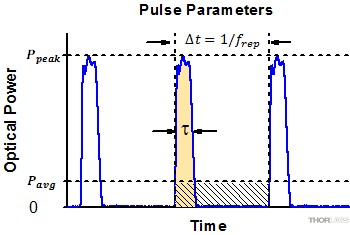
Click to Enlarge
図1: パルスレーザ光の特性を記述するためのパラメータを、上のグラフと下の表に示します。パルスエネルギ (E)は、パルス曲線の下側の黄色の領域の面積に対応します。このパルスエネルギは斜線で表された領域の面積とも一致します。
| パラメータ | シンボル | 単位 | 説明 | ||
|---|---|---|---|---|---|
| パルスエネルギ | E | ジュール[J] | レーザの1周期中に放射される1パルスの全放射エネルギ。 パルスエネルギはグラフの黄色の領域の面積に等しく、 これは斜線部分の面積とも一致します。 | ||
| 周期 | Δt | 秒 [s] | 1つのパルスの開始から次のパルスの開始までの時間 | ||
| 平均パワー | Pavg | ワット[W] | パルスとして放射されたエネルギが、1周期にわたって 均一に広がっていたと仮定したときの、 光パワーの大きさ(光パワー軸上の高さ) | ||
| 瞬時パワー | P | ワット[W] | 特定の時点における光パワー | ||
| ピークパワー | Ppeak | ワット [W] | レーザから出力される最大の瞬時パワー | ||
| パルス幅 |  | 秒 [s] | パルスの開始から終了までの時間。一般的にはパルス形状の 半値全幅(FWHM)を基準にしています。 パルス持続時間とも呼ばれます。 | ||
| 繰り返し周波数 | frep | ヘルツ [Hz] | パルス光が放射される頻度を周波数で表示した量。 周期とは逆数の関係です。 | ||
計算例
下記のパルスレーザ光を測定するのに、最大入力ピークパワーが75 mW
のディテクタを使用するのは安全かどうかを計算してみます。
- 平均パワー: 1 mW
- 繰り返し周波数: 85 MHz
- パルス幅: 10 fs
1パルスあたりのエネルギは、

と低いようですが、ピークパワーは、

となります。このピークパワーはディテクタの
最大入力ピークパワーよりも5桁ほど大きく、
従って、上記のパルスレーザ光を測定するのに
このディテクタを使用するのは安全ではありません。
Click to Enlarge
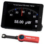
ワイヤレスパワーメータPM160とiPad mini(付属していません)。PM160はApple社のモバイルデバイスを使ってリモート操作が可能です。
こちらでは当社のパワーセンサおよびエネルギーセンサのラインナップをご紹介しています。対応するパワーメーターコンソールとインターフェイスについては右下の表をご覧ください。
下記のパワーセンサおよびエネルギーセンサのラインナップのほかに、当社ではフォトダイオードまたはサーマルセンサのどちらかを内蔵するオールインワン型のワイヤレス機能付きパワーメータや小型USBパワーメータ、およびコンソール、センサーヘッド、ポスト取付け用のアクセサリを含むパワーメーターキットもご用意しております。
当社では4種類のセンサをご用意しております:
- フォトダイオードセンサ: フォトダイオードセンサは感度が波長に依存するので、単色光源もしくは単色に近い光源のパワー測定用に設計されています。このセンサから出力される電流は、入射光パワーと波長によって決まります。この電流はトランスインピーダンスアンプにより、入力電流に比例した電圧を出力します。
- サーマルセンサ: サーモパイルセンサは、広い波長範囲で比較的平坦な応答特性を持つ材料から作られているので、LEDやSLDなどの広帯域光源のパワー測定に適しています。このセンサは、入射光パワーに比例した電圧を出力します。
- サーマル位置&パワーセンサ: これらのセンサでは4つのサーモパイルセンサが正方形の4象限に配置されています。ユニットは各象限からの出力電圧を比較してビームの位置を算出します。
- 焦電エネルギーセンサ: 焦電センサは焦電効果を通じて出力電圧を発生しパルス光源の測定に適しています(ディテクタの時定数によって繰返し周波数は制限されます)。このセンサは、入力パルスエネルギに比例したピーク電圧を出力します。
| Console Compatibility | ||||||||
|---|---|---|---|---|---|---|---|---|
| Console Item # | PM100A | PM100D | PM400 | PM5020 | PM101 Series | PM102 Series | PM103 Series | PM100USB |
| Photodiode Power |  |  |  |  |  | - |  |  |
| Thermal Power |  |  |  |  |  |  | - |  |
| Thermal Position | - | - |  |  | - |  | - | - |
| Pyroelectric Energy | - |  a a |  a a |  | - | - |  |  a a |
パワー&エネルギーセンサのセレクションガイド
当社のパワー&エネルギーセンサの仕様を比較する際には、2種類の選択をします。下の表(展開できます)では、当社のセンサを種類別に分類して(フォトダイオード、サーマル、焦電)、主な仕様を記載しています。
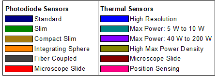
またその下のセレクションガイドのグラフでは、当社のフォトダイオードならびにサーマルパワーセンサの全ラインナップを波長範囲(左)そしてパワー範囲(右)で比較できるようになっています。枠内には型番とセンサの仕様の範囲が記載されています。グラフにより、特定の波長範囲またはパワー範囲に適したセンサーヘッドが特定しやすくなっております。
| Photodiode Power Sensors |
|---|
| Thermal Power Sensors |
|---|
| Thermal Position & Power Sensors |
|---|
| Pyroelectric Energy Sensors |
|---|
センサのラインナップ
(波長範囲)
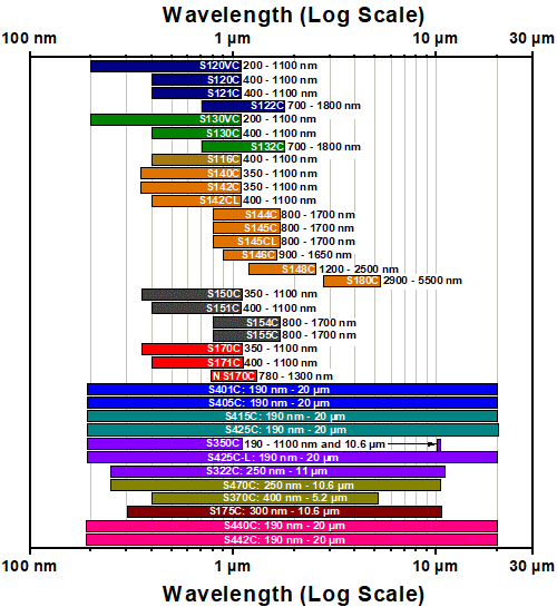
センサのラインナップ
(パワー範囲)
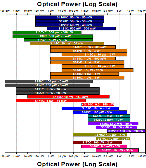
| Posted Comments: | |
user
(posted 2024-11-13 15:11:28.17) Is S401C appropriate to measure 10Hz ns laser pulse at 355nm? expected pulse energy is 10 µJ ~ 1mJ corresponding to the 0.1 ~ 10 mW average power. The beam spot is ~ 5mm x 5mm. I expect 1 percent resolution since the stated resolution is 1 µW. hkarpenko
(posted 2024-11-13 08:14:38.0) Dear customer,
thank you for your feedback.
It´s not possible to measure the average power directly with the S410C and your laser parameters. The problem is the low repetition rate of 10Hz, which the sensor is still capable of following. However you could take a record over a period of time and estimate the average power from that. This can be done within the optical power monitor software. I contact you directly to discuss this further with you. Manuel Jerez
(posted 2024-07-08 11:01:44.22) Good afternoon,
We have tried to measure optical power with your S401C device, as follows: An optical fibre faces the sunlight, guiding the radiation to the photodetector, which is located in a thermally insulated room. The results we get are very strange, with sudden drops in the measurement, and very irregular values. Is there any reason why this might happen? Thank you hchow
(posted 2024-07-09 03:17:15.0) Dear Mr. Jerez, thank you for your enquiry. Depending on how much light is coupled through your fiber into the S401C, you could possibly expect huge fluctuations in the measured optical power. This is due to unstable turbulent nature of the earth's lower atmosphere which can cause the amount of light making it through to the ground to be unstable at best. In any case, I will reach out to you in a separate email to address your concerns. Thank you. user
(posted 2024-06-13 09:14:29.643) Question about the S425C-L:
Do you have data on the change in the absorbance as a function of ambient temperature (I am specifically interested in 780 nm and 1560 nm).
Could it be that e.g. the sensor overestimates the power at 780 nm by a few percent while underestimating the power at 1560 nm (in two separate measurements)? In order words, can the calibrated absorbance curve be "tilted" to lower or higher wavelengths compared to the correct absorbance curve? hchow
(posted 2024-06-14 06:06:28.0) Dear User, no unfortunately we do not have any data with respect to absorbance versus ambient temperature. With an increase in ambient temperature, the sensitivity of the thermopile sensor decreases. The sensitivity given as volt per absorbed radiation is lower at higher ambient temperatures. The consequence of which is that the whole sensitivity curv is shifted at different voltage levels depending upon the ambient temperature. Thus, the gradient of the curves (which is proportional to the thermopile sensitivity) decreases with increasing ambient temperature. Our thermopile sensors are calibrated at room temperature, so any sharp increase or decrease in temperature will cause issues with the voltage reading. The absorbance coating does play role in the amount of transmitted heat being converted into voltage, but this is counteracted through our calibration process and the responsivity values recorded on the EEPROM chip of our thermal sensors. hchow
(posted 2024-06-14 06:06:28.0) Dear User, no unfortunately we do not have any data with respect to absorbance versus ambient temperature. With an increase in ambient temperature, the sensitivity of the thermopile sensor decreases. The sensitivity given as volt per absorbed radiation is lower at higher ambient temperatures. The consequence of which is that the whole sensitivity curv is shifted at different voltage levels depending upon the ambient temperature. Thus, the gradient of the curves (which is proportional to the thermopile sensitivity) decreases with increasing ambient temperature. Our thermopile sensors are calibrated at room temperature, so any sharp increase or decrease in temperature will cause issues with the voltage reading. The absorbance coating does play role in the amount of transmitted heat being converted into voltage, but this is counteracted through our calibration process and the responsivity values recorded on the EEPROM chip of our thermal sensors. PHAM VU
(posted 2022-10-26 19:04:24.527) I have bought PM100USB (SN 1914996) and the sensor S302C (SN M00794496) but it lack of calibration certificate.
Could you please help check and provide it?
Thank and regards,
Vu hchow
(posted 2022-10-27 04:26:56.0) Dear Mr. Vu, thank you for your enquiry. I will personally reach out to you to provide this information. Thank you. Andrey Kuznetsov
(posted 2022-10-21 12:48:23.04) Can you please update the website with all the products' Responsivity V/W? hchow
(posted 2022-10-25 08:09:47.0) Dear Mr. Kuznetsov, thank you for your enquiry. We do offer an analog to the responsivity graphs that you see for our photodiode sensors, and they are the absorbance versus wavelength graphs. I will personally reach out to you for more information. hchow
(posted 2022-10-25 08:34:59.0) Thank you and have a nice day! 叶 先生
(posted 2022-08-05 16:21:05.133) 请问,最大能量密度是在多少nm下测的呢,规格书中只注明了脉宽。谢谢 Jimm Wu
(posted 2022-02-12 00:23:41.467) Hi,
Can I ask several questions?
1. Is this item only the head? Does itself work to give the intensity of the light?
2. Where to get the intensity value because I don't see any viewing screen?
3. Does this head give the light intensity in the unit W/cm2 or mW/cm2?
4. Do I need to order other accessories to work together with this head?
Thank you very much for answering my questions, these questions are very important for my research. I just want to find a good sensor for my research. I saw this device in one published publications, so I think it should be ideal for my research.
I will appreciate it if you can respond to me as soon as possible. soswald
(posted 2022-02-15 06:50:30.0) Dear Jimm Wu,
thank you for your feedback.
The S302C is indeed only the sensor head and for readout a power meter console (https://www.thorlabs.de/newgrouppage9.cfm?objectgroup_id=3341) or interface (https://www.thorlabs.de/newgrouppage9.cfm?objectgroup_ID=4037) is required.
The head measured the optical power in W. Conversion to an irradiance in W/cm² or mW/cm² requires that you know the beam diameter incident on the sensor.
I have reached out to you directly to discuss your application in more detail. 程生 程
(posted 2021-11-03 02:05:49.85) S314价格多少? YLohia
(posted 2021-12-23 11:20:53.0) Thank you for contacting Thorlabs. An applications engineer from our team in China (techsupport-cn@thorlabs.com) has reached out to you directly regarding this. Ronald Sipkema
(posted 2020-07-14 09:06:51.93) L.S.,
I'm interested in using the S425C in combination with either a PM101 or PM100USB for OEM use / integration into a machine. Is it possible to order the sensor with a different cable length or alternatively shorten or lengthen the fixed cable attached to the sensor head ourselves? What would be practical limits on the cable length from sensor to meter?
Similarly the PM16-425 might also be an interesting solution, except for the fixed cable length and the fact that the combined electronics / USB plug probably won't fit through a cable carrier or cable hose. Are there options for changing cable length on those sensors? dpossin
(posted 2020-07-16 08:23:45.0) Dear Ronald,
Thank you for your feedback. We did not test at what length the data transfer does not work any more but up to 3m works for sure. We can either offer special power heads with longer cables or you lengthen the cable yourself. The cable of the USB powermeter PM16-425 can be easily extended by a USB to USB extension cable. Alp Ucak
(posted 2020-06-26 12:09:54.14) Hello, at our laboratory, we are using S350C to measure power. Our beam diameter is about 3mm fwhm and the average power is 25W with 350fs laser pulses. At our measurements, we observe an initial rise and we suspect of the powermeter heating problems. It is getting about 45 celsius degrees. Does that create a problem? Should we use a fan or is there another solution? dpossin
(posted 2020-07-02 10:02:19.0) Dear Alp,
Thank you for your feedback. Most probably the average power of your laser is too high which leads to the fact that the heat sink is not able to dissipate all the heat. I am reaching out to you in order to provide further help. Joseph Donovan
(posted 2019-09-18 08:11:55.98) Hi,
I was wondering if the surface of the S425C-L can tolerate short pulsed sources well (the S370C doesn't have enough power handling for our needs).
The laser we're using is 1035 nm, max. power 60W (though will be mostly used around 20W), ~300fs pulses at 1MHz, ~3mm beam diameter. dpossin
(posted 2019-09-20 02:49:18.0) Dear Joseph,
Thank you for your feedback. We do not tested this but we have at least one customer who uses our high power thermal sensors in the fs regime at a pulse peak power of 0.1 MW. At the repetition rate you would like to use the laser, the operating mode can be seen as quasi CW (continues wave). In case you want to use the laser at a average power of 20W you will get a pulse peak power of about 67 MW. At 20W, the heat dissipation should be no problem but I am a bit concerned if the absorption layer on the detector surface can survive the high peak power. Andrey Kuznetsov
(posted 2019-04-11 21:31:28.367) What are the noise figures for all the products in units of Watts? This would help to choose a meter based on how sensitive the measurement can be while not being overpowered by the noise. nreusch
(posted 2019-04-18 05:04:50.0) This is a response from Nicola at Thorlabs. Thank you for your suggestion! The optical power range specification in combination with the resolution (both specified in Watts) should allow you to determine whether your optical signal can be detected. These features contain all limiting factors including noise. gizem.alpakut
(posted 2019-01-22 08:00:48.627) Hi, I have a question regarding S425C-L and S121C pwoermeter sensors. Whenever I measure a specific power value using both of them, I always get different results. S425C-L always gives 50% less power value than S121C does. I am well aware that S425C-L is a thermal power sensor and other is a photodiode, I used PM100D and PM100USB as power meter consoles, which automatically recognize the console type. What can be the resson for that difference? Is there a way to fix this problem? Thanks in advance. nreusch
(posted 2019-01-23 10:50:02.0) This is a response from Nicola at Thorlabs. Thank you very much for your inquiry. You are right about the fact that such differences are mostly due to the different nature of both sensors. This is especially the case for e.g. broadband sources, for larger angles of incidence (relevant for the photodiode sensor) or for pulsed sources. I will get back to you directly to discuss your specific application. spanna
(posted 2018-12-30 14:08:20.63) Dear Thorlabs, I have two questions regarding the S425C-L model:
1. Below what power I can safely remove the heatsink, my laser provides 6mJ (6W @ 1kHz rep.rate) 35fs pulses with 11mm full width 1/e2 spot size?
2. Does the heatsink removal affect the detector calibration or its reading in any way?
Thanks in advance swick
(posted 2019-01-08 04:00:56.0) This is a response from Sebastian at Thorlabs. Thank you for the inquiry.
1. When measuring low optical powers we recommend for stability reasons to use thermal detectors with heat-sinks.
Removing the heat sink provides the option to use other type of heat-sinks like water-cooling.
2. Calibration should not be affected if heat-sink is replaced with an other appropriate one.
I contacted you directly for further discussion. cwong3
(posted 2017-01-16 18:00:18.07) Hi there. Can you tell me what the max energy density would be for a 30 fs pulse? I'm mostly interested in the S470C and S310C. Thanks. wskopalik
(posted 2017-01-17 05:13:38.0) This is a response from Wolfgang at Thorlabs. Thank you very much for your inquiry.
Unfortunately, we don't have specifications for the maximum energy density for fs pulses. Depending on the exact laser parameters (wavelength, pulse energy, repetition rate, etc.) one of our sensors might however still be suitable.
I have contacted you directly to further discuss your requirements and to look for a suitable sensor. arkke.eskola
(posted 2016-10-27 12:06:48.73) Hi,
I am searching a (thermal) sensor, which would work both with excimer laser (193, 248, and 351 nm) and Nd:YAG laser (213, 266, 355, and 532 nm). I am thinking your S350C sensor due to its large aperture size and wide wavelenght range. Could you please comment its suitability for this purpose; especially I would like to know whether there might appear any issue(s) to use S305C to measure (short) Nd:YAG laser pulse energies. Or should I think about pyroelectric energy sensors?
Thanks,
Arkke Eskola wskopalik
(posted 2016-10-28 05:19:58.0) This is a response from Wolfgang at Thorlabs. Thank you for your inquiry.
Thermal sensors are generally a good choice to measure the average power of pulsed lasers. It depends on the exact laser parameters which sensor model is the most suited (i.e. wavelength, pulse energy, pulse width, repetition rate, beam diameter). These parameters are necessary to make sure that the sensor can handle the power levels of the laser and will not be damaged by it.
I will contact you directly to further discuss your requirements. kedves
(posted 2016-04-13 18:29:51.247) Hello, I am looking for a power meter for a femtosecond laser of about 25 mJ pulse energy, 10 Hz repetition rate (i.e. 250 mW average power), and 40 fs pulse duration (i.e. 625 GW pulse peak power) and 15 mm pulse diameter. Which of your products would you recommend that can tolerate this high peak power too? shallwig
(posted 2016-04-14 10:34:42.0) This is a response from Stefan at Thorlabs. Thank you very much for your inquiry. At the moment we have no sensor available which is specified to stand 625 GW peak power and 353,7 GW/cm2 peak power density. I will contact you directly to discuss if there is a special solution we can offer. mastron
(posted 2016-02-24 19:42:46.833) I am looking into power meters and sensors for measurements of ultrafast pulsed lasers (pulses <250fs at 1khz). Would the S470C be appropriate for this kind of measurement? I wouldn't need shot-to-shot resolution; just to be able to measure pulse energies in several ranges: low uJ (so at 1 khz, low mW range), ~500mW, and ~2W without damaging the power sensor. Also, are calibration options available for multiple wavelength regions? I'd like to be able to measure visible, 800 nm, and near to mid-IR (so around 1.5, 2, 5, and 6 um) accurately. shallwig
(posted 2016-02-25 10:16:16.0) This is a response from Stefan at Thorlabs. Thank you very much for your inquiry due to its long response time (<2s) as typical for thermal sensors average power measurements of pulsed sources are possible. The calibration and measurement uncertainty of this sensor are specified from 250nm – 10,6µm. More information about the calibration of our thermal heads can be found in the power meter tutorial in the “calibration “ Tab here: http://www.thorlabs.com/newgrouppage9.cfm?objectgroup_id=6188
I will contact you directly to discuss your application and your parameters in more detail. user
(posted 2015-12-16 15:42:00.627) In addition to my question below, would you please advice me if you conducted calibration with any emmersion oil? How would it be calibrated with angled beam? shallwig
(posted 2015-12-16 05:09:11.0) This is a response from Stefan from Thorlabs. Thank you again for your for your inquiry. We calibrate the sensor S175C at 1064nm with a collimated laser at 100mW, the beam hits the sensors surface perpendicular. Apart from the calibration at 1064nm we do perform a reflectivity measurement were the reflectivity of the coating gets measured from 266 – 1064nm .
In our power meter tutorial the whole process gets described in detail: http://www.thorlabs.com/newgrouppage9.cfm?objectgroup_id=6188
We have a NIST traceable reference built in a integrating sphere and measure the spectral intensity distribution. Afterwards we put the sensor under test in and measure the spectral reflectivity again. The difference between both curves tells us about the reflectivity of the sensors absorber surface. This is the calibration curve you also get delivered with the sensor.
But there is no NIST standard available which allows to calibrate the sensors with angled beams so far. Therefore we cannot specify any measurement accuracy for this measurement task. user
(posted 2015-12-16 13:57:56.547) I am interested in you S175C sensor to measure oure Ti:Sa laser under 20X objective(oil emmersion). We can't know about real power under the objective as we have not had any sensor. But guessing it would be 500mW-less than 1W. Can we use your S175C for our measurment? shallwig
(posted 2015-12-16 04:37:05.0) This is a response from Stefan at Thorlabs. Thank you very much for your inquiry. For estimation how suitable this sensor is for power measurement of your Ti:Sa I would need further information about the beam. We specify for the sensor a maximum average power density of 200W/cm2 and for µs Pulses and a max pulse energy density of 0.1J/cm2 and 1J/cm2 for 1ms pulses. You can find these information in the spec sheet: http://www.thorlabs.de/thorcat/MTN/S175C-SpecSheet.pdf
The measurement accuracy we specify is only valid for parallel beams with diameter >1mm. I would like to discuss your application in more detail with you directly, unfortunately you left no email address. Please feel free to contact me at europe@thorlabs.com hsynvnvural
(posted 2015-11-20 09:55:12.33) Is there any difference between CW/Pulsed Laser average power measurement for thermopile sensors? Is the uncertainty same for both measurement for S350C and S470C sensors? shallwig
(posted 2015-11-20 10:09:03.0) This is a response from Stefan at Thorlabs. Thank you very much for your inquiry. In general Thermopile sensors have a very slow response time, for the S470C we specify <2s. Depending on the repetition rate of your pulsed source multiple of pulses will hit the active surface before a measurement point is taken. The measurement uncertainty for the S350C and S470C can be found in the specs table: ±3% @ 351 nm; ±5% @ 190 - 1100 nm (S350C) and ±3% @ 1064 nm; ±5% @ 250 nm - 10.6 µm (S470C)
A main difference apart from the power range is the detector type. The S350C is a thermal surface absorber while the S470C is a thermal volume absorber. Thermal volume absorbers have significantly higher responsivities, which allow them to detect very low power levels and short (ns) pulses. However, this improvement usually comes at the expense of response time. I will contact you directly to check which sensor is suited for your application. Paul.taylor
(posted 2015-03-20 11:12:45.53) Can you read the voltage direct from the head via a Plc analog input card? If so - what rough calibration V/W is it? shallwig
(posted 2015-03-23 06:13:37.0) This is a response from Stefan at Thorlabs. Thank you very much for your inquiry. You can use a PLC analog input card to read out the voltage directly by taking the generated thermo voltage from Pin 3 and 8 of the D-Sub connector. Please take a look into the “Pin Diagrams” Tab on the website http://www.thorlabs.com/NewGroupPage9.cfm?ObjectGroup_ID=3333 With the sensor head you will get a calibration certificate where the sensitivity at our calibration sources (1062nm) is listed with an uncertainty of +/-3%.
Depending on which sensor you are interested in the sensitivity is between 0,1mV/W and about 100mV/W. Thus you have to deal with very small voltages. Further information about how our thermal sensors get calibrated can be also found in the power meter tutorial on our website: http://www.thorlabs.com/newgrouppage9.cfm?objectgroup_id=6188 in the “calibration” tab. I will contact you directly to discuss your application in more detail. tonyhongxp
(posted 2015-02-10 22:20:54.77) would the thermal power meter work below 190 nm? The absorption curve does not seem to fall at wavelength below 190 nm. tschalk
(posted 2015-02-11 08:03:01.0) This is a response from Thomas at Thorlabs. Thank you very much for your inquiry. You can use the sensor below 190nm but we dont have specific informaiton about the sensitivity and we dont have the possibility to calibrate the sensor below that wavelength. I will contact you directly to discuss your application. user
(posted 2011-11-28 09:07:26.0) A response from Tyler at Thorlabs: Hello Krister, The thermal power meter sensors that Thorlabs sells use a thermopile sensor to measure the incident power. These sensors would not be an out-of-the-box solution for a non-contact temperature sensor. We will contact you to discuss your application and possible solutions. krister.magnusson
(posted 2011-11-28 05:57:45.0) This product measures light intensity. Does it also include a laser which send out a detection signal wich is analyzed? That is, how does it operate?
I am looking for a non-contact temperature sensor (not pyrometer).
Best regards,
Krister Magnusson jjurado
(posted 2011-07-08 15:18:00.0) Javier Jurado: Response from Javier at Thorlabs to last poster: We do offer a cap that you can use to cover the entrance port of the S302C sensor. The part number is SM1CP1:
http://www.thorlabs.com/NewGroupPage9.cfm?ObjectGroup_ID=3519
Please do not hesitate to contact us at techsupport@thorlabs,com if you have any further questions. user
(posted 2011-07-08 15:50:53.0) I ordered S302C and I would like protect its window. Do you sell a cap for it? jjurado
(posted 2011-06-02 11:34:00.0) Response from Javier at Thorlabs to halverso: Thank you very much for contacting us. With a maximum incident power density spec of 200W/cm^2, the S302C should work for your application. However, other parameters such as wavelength range, minimum incident power, and beam diameter are important, as well, in order to determine the most suitable sensor. I will contact you directly to discuss these details. halverso
(posted 2011-06-02 09:18:06.0) I want to measure power on a stable solar simulator. Expected value is 100mW/cm2. The S302C appears to be ideal for my purpose, but I wanted to confirm. Thanks. apalmentieri
(posted 2010-02-22 22:55:57.0) A response from Adam at Thorlabs to malayk: The S302C sensors are not compatible with the old PM100 power meters. They are compatible with the new PM100D power meter. I will contact you directly to help provide you with the best possible solution that suits your needs. malayk
(posted 2010-02-22 22:00:52.0) Is the S302C sensor compatible with the old PM100 power meter? |

| Item #a | S401C | S405C |
|---|---|---|
| Sensor Image (Click the Image to Enlarge) | 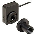 | 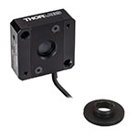 |
| Wavelength Range | 190 nm - 20 µm | 190 nm - 20 µm |
| Optical Power Range | 10 µW - 1 W (3 Wb) | 100 µW - 5 W |
| Input Aperture Size | Ø10 mm | Ø10 mm |
| Active Detector Area | 10 mm x 10 mm | 10 mm x 10 mm |
| Max Optical Power Density | 500 W/cm² (Avg.) | 1.5 kW/cm² (Avg.) |
| Detector Type | Thermal Surface Absorber (Thermopile) with Background Compensation | Thermal Surface Absorber (Thermopile) |
| Linearity | ±0.5% | ±0.5% |
| Resolutionc | 1 µW | 5 µW |
| Measurement Uncertaintyd | ±3% @ 1064 nm ±5% @ 190 nm - 10.6 µm | ±3% @ 1064 nm ±5% @ 250 nm - 17 µm |
| Response Timee | 1.1 s | 1.1 s |
| Cooling | Convection (Passive) | |
| Housing Dimensions (Without Adapter) | (1.30" x 1.69" x 0.59") | 40.6 mm x 40.6 mm x 16.0 mm (1.60" x 1.60" x 0.63") |
| Temperature Sensor (In Sensor Head) | NTC Thermistor | NTC Thermistor |
| Cable Length | 1.5 m | |
| Post Mounting | Universal 8-32 / M4 Taps (Post Not Included) | Universal 8-32 / M4 Taps (Post Not Included) |
| 30 mm Cage Mounting | - | Two 4-40 Tapped Holes & Two Ø6 mm Through Holes |
| Aperture Threads | Internal SM05 | Internal SM05 |
| Accessories | Internally SM1-Threaded Adapter with an Internally SM05-Threaded Light Shield | Adapter with External SM05 and External SM1 Threads |
| Compatible Consoles | PM400, PM100D, PM100A, and PM5020 | |
| Compatible Interfaces | PM101, PM101A, PM101R, PM101U, PM102, PM102A, PM102U, and PM100USB | |
- 1 μWまたは5 μWの高分解能
- S401CとS405Cにはセンサーヘッドの温度をモニタするサーミスタ付き
- S401C: バックグラウンド補正により低ドリフトで測定
- S405C: 最大1.5 kW/cm²の平均パワー密度に対応

Click to Enlarge
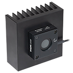
付属の遮光体を取り付けたサーマルセンサS401C
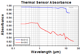
当社では低パワーの光源を高分解能で測定するために設計された広帯域サーマルパワーセンサを2種類ご用意しております。いずれのサーマルセンサの広帯域コーティングも、下のグラフのように広い波長域において平坦なスペクトル応答特性を示します。Ø10 mmの開口寸法により、スポットサイズの大きいレーザ光源のアライメントや測定が容易です。当社のレンズチューブシステムやSM1ネジ付きファイバーアダプタ(下記参照)への接続用に、各センサにはSM1外ネジが付いているか、あるいはSM1外ネジ付きアダプタが付属しています。
S401Cは、アクティブ型のサーマルバックグラウンド補正により低ドリフトで光パワー測定を行います。これは同様のセンサ回路を2つ使用することで実現しています。1つのセンサ回路はすべてのサーマルパワーセンサが使用するものと同じタイプで、光吸収体からヒートシンクへの熱流量を測定します。もう1つのセンサ回路は周囲温度をモニタします。2つのセンサ回路の測定値が差し引かれるので、レーザのパワー測定におけるサーマルドリフトの影響は最小限に抑えられます (外部からの熱的擾乱がどのようにサーマルパワーセンサの読取値に影響するかについての詳細は、「動作」タブをご覧ください)。こちらのサーマルセンサに使用している広帯域コーティングは、0.19~20 µm(グラフ参照)の波長域で高い吸収を示します。そのため、中赤外域(MIR)の量子カスケードレーザ(QCL)のアライメントや測定にお使いいただけます。付属のSM05内ネジ付き遮光体は、上または下の写真でご覧いただけます。
S405CにはSM05内ネジがあり、SM05レンズチューブに直接取り付けられます。また、当社の30 mmケージシステムにも直接取り付けられます。
当社ではこれらのセンサに対して再校正サービスをご提供しております。再校正サービスの詳細は当社へお問い合わせください。

| Item #a | S415C | S425C |
|---|---|---|
| Sensor Image (Click Image to Enlarge) | 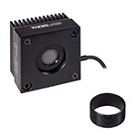 | 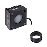 |
| Wavelength Range | 190 nm - 20 µm | 190 nm - 20 µm |
| Optical Power Range | 2 mW - 10 W (20 Wb) | 2 mW - 10 W (20 Wb) |
| Input Aperture Size | Ø15 mm | Ø25.4 mm |
| Active Detector Area | Ø15 mm | Ø27 mm |
| Max Optical Power Density | 1.5 kW/cm² (Avg.) | 1.5 kW/cm² (Avg.) |
| Detector Type | Thermal Surface Absorber (Thermopile) | |
| Linearity | ±0.5% | ±0.5% |
| Resolutionc | 100 µW | 100 µW |
| Measurement Uncertaintyd | ±3% @ 1064 nm ±5% @ 250 nm - 17 µm | ±3% @ 1064 nm ±5% @ 250 nm - 17 µm |
| Response Timee | 0.6 s | 0.6 s |
| Cooling | Convection (Passive) | |
| Housing Dimensions (Without Adapter) | (2.00" x 2.00" x 1.38") | (2.00" x 2.00" x 1.38") |
| Temperature Sensor (In Sensor Head) | NTC Thermistor | |
| Cable Length | 1.5 m | |
| Post Mounting | Universal 8-32 / M4 Taps (Post Not Included) | Universal 8-32 / M4 Taps (Post Not Included) |
| 30 mm Cage Mounting | - | - |
| Aperture Threads | Internal SM1 | Internal SM1 |
| Removable Heatsink | Yes | Yes |
| Accessories | Externally SM1-Threaded Adapter | Externally SM1-Threaded Adapter |
| Compatible Consoles | PM400, PM100D, PM100A, and PM5020 | |
| Compatible Interfaces | PM101, PM101A, PM101R, PM101U, PM102, PM102A, PM102U, and PM100USB | |
- 光パワーの分解能は100 µW
- センサーヘッドの温度をモニタするサーミスタ
- 取り外し可能なヒートシンク
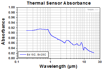
こちらのサーマルパワーセンサは、低~中程度の広いパワー範囲の測定用に設計されています。全ての製品には入射開口部と同心のSM1外ネジ付きアダプタが付属します。このアダプタはØ25 mm~Ø25.4 mm(Ø1インチ)レンズチューブやファイバーアダプタ(下記掲載)を取り付ける際に便利です。S415CおよびS425C筐体の開口にはSM1内ネジが付いています。
このセンサの応答時間は0.6秒以下です。ヒートシンクは取り外しが可能なため、カスタム仕様のセットアップに組み込んだり、ヒートシンクを取り外して水冷式やファン空冷式のものに取り換えるなどのご要望にも対応します。ヒートシンクを交換する場合には、交換後のヒートシンクが用途に適した放熱を行えるようにしてください。
当社ではこれらのセンサに対して再校正サービスをご提供しております。再校正サービスの詳細は当社へお問い合わせください。

- センサーヘッドの温度をモニタするサーミスタ
- S322Cには当社の30 mmケージシステムに対応したケージロッド用タップ穴付き
- S350Cにはスポットサイズの大きなエキシマレーザなどに適したØ40 mmの開口付き
- S425C-Lには取外し可能なヒートシンク
- S322Cはファン空冷式で光パワーの測定範囲は最大200 W
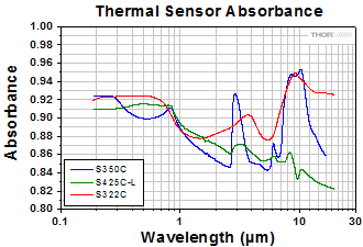
こちらのサーマルパワーセンサは、低~中程度の広いパワー範囲の測定用に設計されています。 S350Cを除くすべての製品には、入射開口部と同心のSM1外ネジ付きアダプタが付属します。これによって、センサにはファイバーアダプタ(下記参照)が使用可能です。また、既存のØ25 mm~Ø25.4 mm(Ø1インチ)レンズチューブシステムに組み込むこともできます。S425C-Lの開口にはSM1内ネジが付いています。
S425C-Lのセンサの応答時間は0.6秒以下です。ヒートシンクは取り外しが可能なため、カスタム仕様のセットアップに組み込んだり、ヒートシンクを取り外して水冷式やファン空冷式のものに取り換えるなどのご要望にも対応します。ヒートシンクを交換する場合には、交換後のヒートシンクが用途に適した放熱を行えるようにしてください。
当社ではこれらのセンサに対して再校正サービスをご提供しております。再校正サービスの詳細は当社へお問い合わせください。
| Item #a | S350C | S425C-L | S322C |
|---|---|---|---|
| Sensor Image (Click Image to Enlarge) | 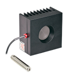 | 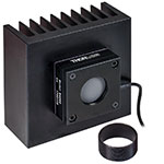 | 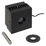 |
| Wavelength Range | 190 nm- 1.1 µm, 10.6 µm | 190 nm - 20 µm | 250 nm - 11 µm |
| Optical Power Range | 10 mW - 40 W (60 Wb) | 2 mW - 50 W (75 Wb) | 100 mW - 200 W (250 Wb) |
| Input Aperture Size | Ø40 mm | Ø25.4 mm | Ø25 mm |
| Active Detector Area | Ø40 mm | Ø27 mm | Ø25 mm |
| Max Optical Power Density | 2 kW/cm² (Avg.) | 1.5 kW/cm² (Avg.) | 4 kW/cm² (Avg., CO2) |
| Detector Type | Thermal Surface Absorber (Thermopile) | ||
| Linearity | ±1% | ±0.5% | ±1% |
| Resolutionc | 1 mW | 100 µW | 5 mW |
| Measurement Uncertaintyd | ±3% @ 1064 nm ±5% @ 190 nm - 1100 nm, 10.6 µm | ±3% @ 1064 nm ±5% @ 250 nm - 17 µm | ±3% @ 1064 nm ±5% @ 266 nm - 1064 nm |
| Response Timee | 9 s (1 s from 0 to 90%) | 0.6 s | 5 s (1 s from 0 to 90%) |
| Cooling | Convection (Passive) | Forced Air with Fanf | |
| Housing Dimensions (Without Adapter, if Applicable) | 100 mm x 100 mm x 54.2 mm (3.94" x 3.94" x 2.13") | 100.0 mm x 100.0 mm x 58.0 mm (3.94" x 3.94" x 2.28") | 100 mm x 100 mm x 86.7 mm (3.94" x 3.94" x 3.41") |
| Temperature Sensor (In Sensor Head) | NTC Thermistor | ||
| Cable Length | 1.5 m | ||
| Post Mounting | M6 Threaded Taps, Includes Ø1/2" Post, 75 mm Long | Universal 8-32 / M4 Taps (Post Not Included) | M6 Threaded Taps, Includes Ø1/2" Post, 75 mm Long |
| 30 mm Cage Mounting | - | - | Four 4-40 Tapped Holes |
| Aperture Threads | - | Internal SM1 | - |
| Removable Heatsink | - | Yes | - |
| Accessories | - | Externally SM1-Threaded Adapter | Externally SM1-Threaded Adapter |
| Compatible Consoles | PM400, PM100D, PM100A, and PM5020 | ||
| Compatible Interfaces | PM101, PM101A, PM101R, PM101U, PM102, PM102A, PM102U, and PM100USB | ||

| Item #a | S370C | S470C |
|---|---|---|
| Sensor Image (Click Image to Enlarge) | 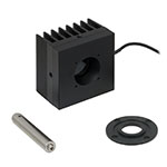 | 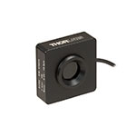 |
| Wavelength Range | 400 nm - 5.2 µm | 250 nm - 10.6 µm |
| Optical Power Range | 10 mW - 10 W (15 Wb) | 100 µW - 5 W (Pulsed and CW) |
| Input Aperture Size | Ø25 mm | Ø15 mm |
| Active Detector Area | Ø25 mm | Ø16 mm |
| Max Optical Power Density | 35 W/cm² (Avg.); 100 GW/cm² (Peak) | |
| Detector Type | Thermal Volume Absorber (Thermopile) | |
| Linearity | ±1% | ±0.5% |
| Resolutionc | 250 µW | 10 µW |
| Measurement Uncertaintyd | ±3% @ 1064 nm ±5% @ 400 nm - 1064 nm | ±3% @ 1064 nm ±5% @ 250 nm - 10.6 µm |
| Response Timee | 45 s (3 s from 0 to 90%) | 6.5 s (<2 s from 0 to 90%) |
| Cooling | Convection (Passive) | |
| Housing Dimensions (Without Adapter, if Applicable) | (2.95" x 2.95" x 2.02") | (1.77" x 1.77" x 0.71") |
| Temperature Sensor (In Sensor Head) | N/A | N/A |
| Cable Length | 1.5 m | |
| Post Mounting | M6 Threaded Taps, Includes Ø1/2" Post, 75 mm Long | Universal 8-32 / M4 Tap (Post Not Included) |
| 30 mm Cage Mounting | Four 4-40 Tapped Holes | - |
| Aperture Threads | - | External SM1 |
| Accessories | - | |
| Compatible Consoles | PM400, PM100D, PM100A, and PM5020 | |
| Compatible Interfaces | PM101, PM101A, PM101R, PM101U, PM102, PM102A, PM102U, and PM100USB | |
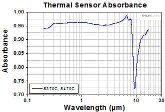
- Nd:YAGレーザの光パワー測定用
- ピークパワーの大きなパルスレーザに適した製品
- S370C: スポットサイズの大きなビームに対応したØ25 mmの開口
- S470C: 平均パワーが小さく、ピークパワーが大きなパルスレーザに対して高感度
サーマルセンサS370CならびにS470Cは、高エネルギーの短パルスレーザ用に設計されています。 すべてのユニットは自由空間光を測定するためにポストに取り付けることができ、またセンサのコネクタ部にはNISTトレーサブルなデータが保存されています。
こちらのサーマルパワーセンサは体積吸収体を使用している点がユニークな特長です。他のサーマルパワーセンサでは表面吸収体が使用されています。体積吸収体はSchott社製ガラスフィルタでできています。入射パルスは吸収され、熱は体積全体に分散されます。このため、表面吸収体の吸収コーティングを損傷するようなパルスでも、体積吸収体ではより安全に測定することができます。
S370Cの開口部はØ25 mmと大きく、スポットサイズが大きいビームの測定に適しており、平均パワー10 mW~10 W(CW)に対応しています。
S370Cと比較してS470Cは応答が速くなっていますが、これはガラス吸収体の体積が小さく、またその他の設計パラメータも速度を上げるために最適化されているためです。その結果、光パワーの測定範囲も異なり、100 µWの低いパワーまで測定できます。 S470Cの開口部はØ15 mmと小さく、また最大平均パワーも5 Wと小さくなっています。分解能は10 µWで、S370Cの250 µWと比較して優れています。
サーマルセンサS370CおよびS470Cは、高出力パルスレーザの高い平均パワーにも高いピークパワー密度にも耐えられます。しかし、こちらのセンサよりもスペクトル範囲が広い、あるいは応答時間が短いセンサをお探しの場合は、当社の焦電エネルギーセンサをご検討ください。
当社ではこれらのセンサに対して再校正サービスをご提供しております。再校正サービスの詳細は当社へお問い合わせください。

| Item #a | S175C |
|---|---|
| Sensor Image (Click Image to Enlarge) | 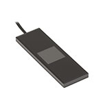 |
| Wavelength Range | 0.3 - 10.6 µm |
| Power Range | 100 µW - 2 W |
| Input Aperture Size | 18 mm x 18 mm |
| Active Detector Area | 18 mm x 18 mm |
| Max Optical Power Density | 200 W/cm2 |
| Detector Type | Thermal Surface Absorber (Thermopile) |
| Linearity | ±0.5% |
| Resolutionb | 10 µW |
| Measurement Uncertaintyc | ±3% @ 1064 nm; ±5% @ 300 nm - 10.6 µm |
| Response Timed | 3 s (< 2 s from 0 to 90%) |
| Housing Dimensions | 76 mm x 25.2 mm x 4.8 mm (2.99" x 0.99" x 0.19") |
| Temperature Sensor (In Sensor Head) | N/A |
| Cable Length | 1.5 m |
| Housing Features | Integrated Glass Cover Engraved Laser Target on Back |
| Compatible Consoles | PM400, PM100D, PM100A, and PM5020 |
| Compatible Interfaces | PM101, PM101A, PM101R, PM101U, PM102, PM102A, PM102U, and PM100USB |
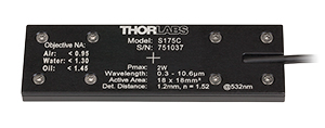
Click to Enlarge
S175Cの筐体の背面には、センサの仕様とビームをセンサの中央に入射させるためのターゲットが刻印されています。
- 顕微鏡の試料面で光を計測できる設計
- 標準的な顕微鏡スライドと同じ設置面積:76.0 mm x 25.2 mm
- 波長範囲:300 nm~10.6 μm
- 100 µW~2 Wの光パワーを測定可能
- コネクタに以下の情報を保存
- センサーデータ
- NISTおよびPTBトレーサブルな校正データ
顕微鏡用スライドサーマルパワーセンサーヘッドS175Cを用いて、顕微鏡システム内の試料面における光パワーを測定できます。このサーマルセンサ は、300 nm~10.6 µmの波長範囲で100 µW~2 Wの光パワーを検出します。センサーヘッドの設置面積は標準的な顕微鏡スライドと同じ76.0 mm x 25.2 mmなので、ほとんどの標準的な正立および倒立顕微鏡に対応しています。
18 mm x 18 mmの検出部は密封された筐体に収納されており、その上にはガラスカバーが付いています。液浸材(水、グリセロール、油など)は、ガラスカバープレートの上につけてください。
右の写真のようにセンサ筐体の背面には、ビームのアライメントと集光を補助するためのターゲットがレーザ刻印されています。標準的な顕微鏡では、このターゲットを用いてビームをアライメントした後、センサーヘッドを反転させて対物レンズに向ければパワーの測定を行うことができます。倒立顕微鏡では、透過照明をオンにしてディテクタ筐体のターゲットとビームを合わせます。これにより、対物レンズの正面中央にセンサがきます。
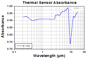
Click to Enlarge
生データはこちらからご覧いただけます。
S175C(ガラスおよび吸収体)の典型的な吸収曲線 注: この曲線は典型値であり、実際の吸収スペクトルはユニットごとに異なります。
センサの仕様とNISTおよびPTBトレーサブルな校正データは、センサーコネクタの非揮発性メモリに保存されており、当社の最新世代のパワーメータで読み出すことができます。精度と性能を維持するために定期的な再校正をお勧めしています。校正頻度は用途にもよりますが、通常1年程度です。再校正サービスについては当社までお問い合わせください。
センサの損傷を防ぐために、ビームが集光されていない位置にセンサを配置することをお勧めいたします。ビームのスポット全体において、平均パワー密度の最大値(Max Average Power Density、左表参照)を超えないことが重要です。
仕様の詳細は「仕様」タブをご覧ください。当社では、低パワーで高分解能な測定が可能なフォトダイオードセンサ付き顕微鏡用スライドセンサーヘッドもご用意しております。詳しい製品説明はこちらからご覧いただけます。

こちらのSM1内ネジ付きアダプタはフォトダイオードパワーセンサ、サーマルパワーセンサ、そしてフォトディテクタをはじめとする当社の全てのSM1外ネジ付き部品とコネクタ付きファイバを接続させることができます。
ナローキーとワイドキーの詳細については、光ファイバとはのページをご覧ください。アダプタが取り付け可能かどうかが不確かな場合には当社までご連絡くさい。
APCアダプタには 2つの窪みがあるので、どちらの面からもスパナレンチSPW909またはSPW801を用いて締め付け可能です。このアダプタをSM1レンズチューブと遮光用途でお使いいただけるように、窪みはディスクを貫通していません。
フェルール用アダプタS120-25は、ロッキングコネクタ機構無しの設計になっています。Ø2.5 mmフェルール付きのファイバーパッチケーブルに対応し、フォトディテクタやパワーセンサを用いた測定を迅速に行うことができます。

※パワーセンサ校正について - 当社のパワーセンサ校正は自動で行われており、測定と同時にセンサ内のメモリにある補正データを書き換えます(出力されるデータは校正前の感度と校正後の感度になります)。また、センサ面(NDフィルタ)が汚れ等で正常に感度測定ができないと判断された場合には、フィルタ交換(無償)してから校正される場合がございますので、ご了承ください。この場合は校正前の感度は測定できません。
| Sensor Type | Sensor Item #s |
|---|---|
| Thermal Power | S175C, S302Ca, S305Ca, S310Ca, S314Ca,S322C, S350C, S370C, S401C, S405C, S415C, S425C, S425C-L, S470C, PM160T, PM160T-HP, PM16-401, PM16-405 |
| Pyroelectric Energy | ES111C, ES120C, ES145C, ES220C, ES245C, ES308C, ES312C, ES408C, ES412C |
Thorlabs offers recalibration services for our Thermal Power and Pyroelectric Energy Sensors. To ensure accurate measurements, we recommend recalibrating the sensors annually. Recalibration of a single-channel power and/or energy meter console or interface is included with the recalibration of a sensor at no additional cost. If you wish to calibrate one or more sensors with a dual-channel console, each sensor and console calibration service will need to be purchased individually.
Please note that the CAL-THPY recalibration service cannot be used for our Thermal Position & Power Sensors; recalibration for these sensors can be requested by contacting Tech Support. The table to the upper right lists the sensors for which the CAL-THPY recalibration service is available.
Requesting a Calibration
Thorlabs provides two options for requesting a calibration:
- Complete the Returns Material Authorization (RMA) form. When completing the RMA form, please enter your name, contact information, the Part #s, and the Serial #s of all sensors or consoles being returned for calibration; in the Reason for Return field, select "I would like an item to be calibrated." All other fields are optional. Once the form has been submitted, a member of our RMA team will reach out to provide an RMA Number, return instructions, and to verify billing and payment information.
- Enter the Part # and Serial # of the item that requires recalibration below and then Add to Cart. If you would like a console calibrated with your sensor, repeat this process for Item # CAL-PM1 or CAL-PM2 below, entering the console Item # and Serial #. A member of our RMA team will reach out to coordinate the return of the item(s) for calibration. Note that each console calibration Item # represents the cost of calibrating a console alone; if requesting a single-channel console calibration with a sensor calibration, the appropriate discount will be applied when your request is processed. Should you have other items in your cart, note that the calibration request will be split off from your order for RMA processing.
Please Note: To ensure your item being returned for calibration is routed appropriately once it arrives at our facility, please do not ship it prior to being provided an RMA Number and return instructions by a member of our team. Pyroelectric energy sensors returned for recalibration or servicing must include the separate BNC to DB9 adapter, which contains the sensor EEPROM.

※パワーセンサ校正について - 当社のパワーセンサ校正は自動で行われており、測定と同時にセンサ内のメモリにある補正データを書き換えます(出力されるデータは校正前の感度と校正後の感度になります)。また、センサ面(NDフィルタ)が汚れ等で正常に感度測定ができないと判断された場合には、フィルタ交換(無償)してから校正される場合がございますので、ご了承ください。この場合は校正前の感度は測定できません。
| Calibration Service Item # | Compatible Consoles & Interfaces |
|---|---|
| Single-Channel | |
| CAL-PM1 | PM100D, PM100A, PM400, PM100USB, PM101 Series, PM102 Series, PM103 Series |
| Dual-Channel | |
| CAL-PM2 | PM5020, Previous-Generation PM320E |
These recalibration services are for the power and/or energy meter electronics of our consoles and interfaces. To ensure accurate measurements, we recommend recalibrating annually. Recalibration of a single-channel console or interface is included with these sensor recalibration services at no additional cost. If you wish to calibrate one or more sensors with a dual-channel console, each sensor and console calibration service will need to be purchased individually. For more details on these recalibration services, please click the Documents (![]() ) icons below.
) icons below.
The table to the upper right lists the power and/or energy meter consoles and interfaces that can be calibrated using the CAL-PM1 and CAL-PM2 recalibration services.
Requesting a Calibration
Thorlabs provides two options for requesting a calibration:
- Complete the Returns Material Authorization (RMA) form. When completing the RMA form, please enter your name, contact information, the Part #, and the Serial # of each item being returned for calibration; in the Reason for Return field, select "I would like an item to be calibrated." All other fields are optional. Once the form has been submitted, a member of our RMA team will reach out to provide an RMA Number, return instructions, and to verify billing and payment information.
- Select the appropriate Item # below, enter the Part # and Serial # of the item that requires recalibration, and then Add to Cart. If you would like to calibrate one or more sensors with your console, repeat this process for the appropriate sensor recalibration service above, entering the console Item # and Serial #. A member of our RMA team will reach out to coordinate return of the item(s) for calibration. Note that each console calibration Item # represents the cost of calibrating a console alone; if requesting a single-channel console calibration with a sensor calibration, the appropriate discount will be applied when your request is processed. Should you have other items in your cart, note that the calibration request will be split off from your order for RMA processing.
Please Note: To ensure your item being returned for calibration is routed appropriately once it arrives at our facility, please do not ship it prior to being provided an RMA Number and return instructions by a member of our team.
 Products Home








 サーマルパワーセンサ