 Products Home
Kurios® Liquid Crystal Tunable Bandpass Filters
- Tunable Bandpass Filters for Visible and NIR Wavelengths
- Ideal for Multispectral and Hyperspectral Imaging
- Available with Fixed or Selectable Bandwidth
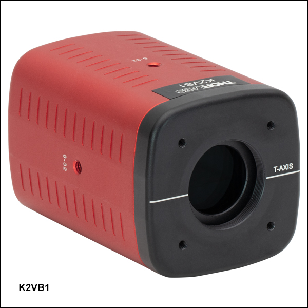
K2VB1
Variable Bandwidth, Ø20 mm CA
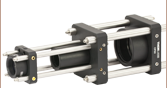
Application Idea
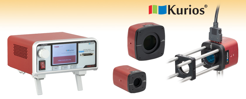
The Kurios® filter heads can be connected to 30 mm cage systems for custom optical assemblies.
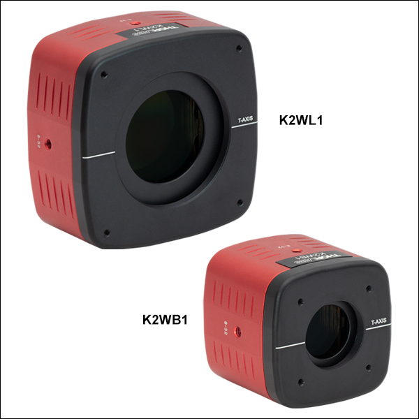
K2WL1
Fixed Bandwidth, Ø35 mm CA
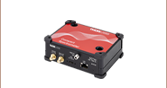
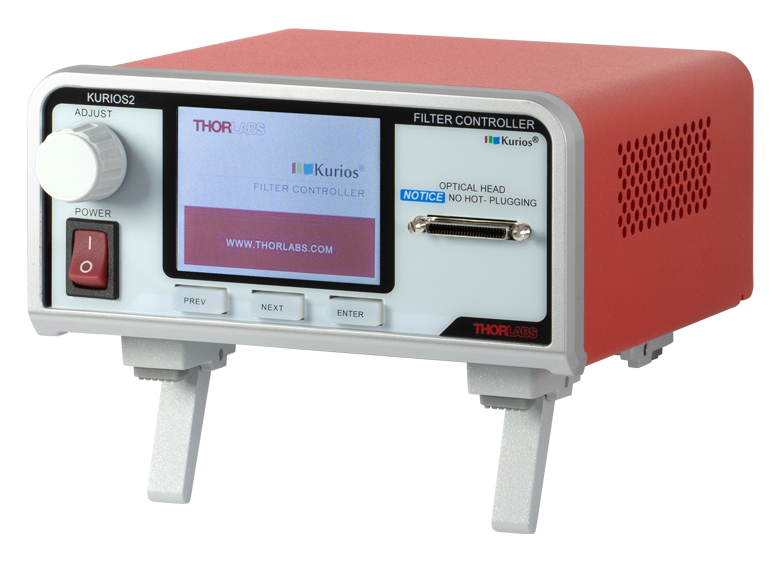
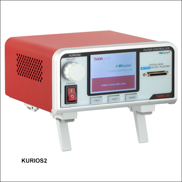
KURIOS2
Controller for Kurios® Filters


Please Wait

Click to Enlarge
A hyperspectral image of a root cell taken using the previous-generation
KURIOS-WB1. Two sample spectrums at the regions indicated are also shown. More details on this measurement are available in the Application Ideas tab.
Features
- Tunable Optical Filters with Fully Programmable Sequences
- Temperature-Controlled Head for Long-Term Stability
- Ø20 mm or Ø35 mm Clear Aperture
- Requires KURIOS2 Controller (Sold Separately Below)
- Provides Local Control via the Front Panel and Remote Control via BNC and USB
- Software and SDK Included (See Software Tab for Details)
- Several Mounting Options
- Three 8-32 (M4 x 0.7) Tapped Holes for Post Mounting
- Internal SM1 (1.035"-40) or SM2 (2.035"-40) Threads on Both Sides
- 4-40 Tapped Holes on Both Sides for 30 mm or 60 mm Cage Systems
- Filters are Factory Calibrated and Include a Test Report (Click Here for a Sample Test Report)
Kurios® Liquid Crystal Tunable Bandpass Filters provide a continuously tunable center wavelength (CWL) in the 420 - 730 nm, 430 - 730 nm, or 650 - 1100 nm range. Most Kurios models have a fixed bandwidth for any given center wavelength. Alternatively, the K2VB1(/M) has user-selectable bandwidth settings of Narrow, Medium, and Wide. The switching time varies depending upon the initial and final wavelengths and on the Kurios' bandwidth setting (for K2VB1(/M) only). See the plots in the tables below for details.
The Kurios optical filters require the KURIOS2 controller for operation (sold separately below). It provides Trigger In, Trigger Out, and Analog In functionality, making these tunable optical bandpass filters ideal for applications that perform multispectral or hyperspectral imaging, as demonstrated in the image to the right. For example, they can be used in conjunction with a monochrome scientific CMOS camera to obtain images with a much higher accuracy for color representation than using a color CMOS camera with a Bayer mosaic. This technique produces true spectral imaging and can thus show spectral features that would otherwise be impossible to detect. Thorlabs' Kurios tunable filters and CMOS cameras are also compatible with our modular Cerna® Microscopy Platform that supports customizable microscopy solutions. For examples of how the Kurios filters can be integrated with the Cerna microscopy platform and standard optomechanical components, please see the Application Ideas tab.
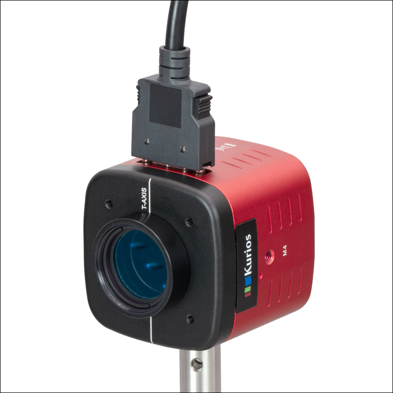
Similar in construction to Lyot and Solc filters, Kurios filters consist primarily of liquid crystal cells that are sandwiched between polarizing elements. Their integrated design enables quick and vibrationless tuning. For added operational stability, a closed-loop temperature control servo is used to maintain the filter head's operating temperature. An LED on the filter head displays red when the head is warming up and green when it is ready to be used.

Click to Enlarge
The back of the filter head contains the same mounting features as the front. The output polarization is rotated by 90° with respect to the input polarization.

Click to Enlarge
The front of the filter head contains internal SM1 or SM2 threads, four
Wavelength Control with KURIOS2 Controller
The controller's front panel provides manual control of the center wavelength and enables programmable switching sequences, as described in the Control tab. It also features three menu buttons that can be used to toggle through various operating modes. For the K2VB1(/M), the buttons toggle between Narrow, Medium, and Wide (the three selectable bandwidths), as well as beam-blocking mode ("Black"). For the fixed bandwidth models, the buttons toggle between the only bandwidth available and Black mode. Please see the Control tab for more details.
The KURIOS2 controller also offers three BNC connectors (Trigger In, Trigger Out, and Analog In) that allow a Kurios filter to be synchronized with a wide range of other devices, such as scientific cameras and motion control stages. Each Kurios filter is factory calibrated and ships with a switching time map so that the user may optimize their system for the specific filter.
Click to Enlarge
The K2WB1/M Filter Head With the Included FESH0750 Hard-Coated Shortpass Filter
Transmission and Polarization
The liquid crystal optics in Kurios filters are not sensitive to the direction of propagation, allowing the filter to be used in either direction. The first element in the filter head is a linear polarizer and each face is marked with a white line (see the images to the left) that indicates the transmitted polarization direction. For maximum transmission, the input beam should be linearly polarized and aligned with this polarization axis. Please note that since Kurios filters are structured like Lyot and Solc filters, the polarization axis rotates by 90° through the filter head. To obtain the specified attenuation of out-of-band wavelengths, the input beam should be well collimated, since the filter head's field of view is ±6°.
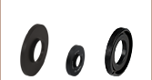
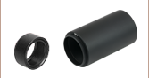
A lens-tube-mounted hard-coated 750 nm shortpass filter is included with our K2WB1(/M), K2WL1(/M), K2XL1(/M), and K2VB1(/M) Tunable Filters for visible wavelengths. Use of this filter is recommended to protect the filter head components from excessive IR illumination.
Mounting Options
These tunable filters are post mountable via three 8-32 (M4 x 0.7) taps on the sides of the housing. In addition, four 4-40 tapped holes on the front and back faces provide compatibility with our 30 mm or 60 mm cage systems, depending on the model. The front and back faces of the housing are internally SM1- (1.035"-40) or SM2- (2.035"-40) threaded. These threads accommodate Ø1" or Ø2" lens tubes, respectively. To connect the K2WB1(/M) or K2VB1(/M) filter to a camera, use our SM1A39 SM1-to-C-Mount thread adapter together with an appropriate tube lens.
| Fixed Bandwidth Tunable Filters | |||||
|---|---|---|---|---|---|
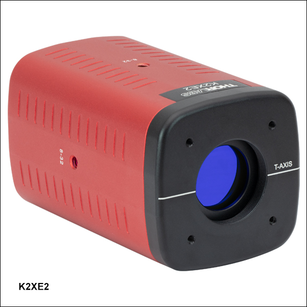
| Item # | K2WB1(/M) | K2WL1(/M) | K2XL1(/M) | K2XE2(/M) | |
| Wavelength Range | 420 - 730 nm | 430 - 730 nm | 650 - 1100 nm | ||
| Bandwidth (FWHM)a | 35 nm at 550 nm | 10 nm at 550 nm | 17 nm at 850 nm | ||
| Switching Speedb | <150 ms | <250 ms | <760 ms | ||
| Clear Aperture | Ø20 mm | Ø35 mm | Ø20 mm | ||
| Polarized Transmissionc | 45% at 550 nm | 17% at 550 nm | 44% at 850 nm | ||
| Out-of-Band Blocking | OD > 2 | ||||
| Minimum Incremental Step Size | 1 nm | ||||
| Tuning Accuracy | ±FWHM/10 | ||||
| Field of View | ±6° | ||||
| Wavelength Uniformity | FWHM/8 | FWHM/4 | |||
| Damage Threshold | Pulsed (ns) | 0.1 J/cm2 | 0.1 J/cm2 (810 nm, 10 Hz, 7.2 ns, Ø216 µm) | ||
| Pulsed (fs) | 0.02 J/cm2 (532 nm, 76 Hz, 100 fs, Ø162 µm) | 0.006 J/cm2 (800 nm, 100 Hz, 36.4 fs, Ø189 µm) | |||
| CW | 0.8 W/cmd (532 nm, Ø0.471 mm) | - | |||
| Filter Head Dimensions | 52.6 mm x 52.6 mm x 48.5 mm (2.07" x 2.07" x 1.91") |
79.0 mm x 79.0 mm x 39.5 mm (3.11" x 3.11" x 1.56") |
79.0 mm x 79.0 mm x 60.5 mm (3.11" x 3.11" x 2.38") |
52.6 mm x 52.6 mm x 87.5 mm (2.07" x 2.07" x 3.44") |
|
| Filter Head Front/Rear Threading | SM1 (1.035"-40) Internal Threads | SM2 (2.035"-40) Internal Threads | SM1 (1.035"-40) Internal Threads | ||
| Filter Head Mounting Options | 8-32 (M4 x 0.7) Tap for Post Mounting (3 Places) 4-40 Taps for Cage System |
||||
| Operating Temperature | 15 to 40 °C | ||||
| Storage Temperature | -15 to 65 °C | ||||
| KURIOS2 Controller | |
|---|---|
| Electrical Characteristics | |
| Adjustable Output Voltage | 0 to ±25 V RMS |
| Voltage Resolution | 1.0 mV |
| Switching Frequency | 2000 ± 1 Hz, 50% Duty Cycle |
| Slew Rate | 10 V/μs |
| DC Offset | ±5 mV |
| Warm-Up Time | 30 min |
| USB Port | USB Standrad B Plug |
| Power Compatibility | 110 - 240 VAC, 50 - 60 Hz Operation, Location Specific Power Cord Included |
| Maximum Ratings | |
| Maximum External Input Voltage | 5 VDC |
| Maximum Output Current | 50 mA |
| Maximum Heating Current | 900 mA |
| Operating Temperature Range | 10 to 40 °C |
| Maximum Relative Humidity | 85% |
| General Specifications | |
| Dimensions (L x W x H) | 177.0 mm x 154.0 mm x 85.0 mm (6.97" x 6.03" x 3.35") |
| Weight | 0.89 kg |
| Selectable Bandwidth Tunable Filter | ||
|---|---|---|
| Item # | K2VB1(/M) | |
| Wavelength Range | 420 - 730 nm | |
| Bandwidth, CWL = 550 nma | Narrow: 10 nm FWHM Medium: 18 nm FWHM Wide: 32 nm FWHM |
|
| Switching Speedb | Narrow: <750 ms Medium: <500 ms Wide: <250 ms |
|
| Clear Aperture | Ø20 mm | |
| Polarized Transmission, CWL = 550 nmc |
Narrow: 13% Medium: 17% Wide: 20% |
|
| Out-of-Band Blocking | OD > 2 | |
| Minimum Incremental Step Size | 1 nm | |
| Tuning Accuracy | ±FWHM/10 | |
| Angle of Incidence (Field of View) | ±6° | |
| Wavelength Uniformity | FWHM/4 | |
| Damage Threshold | Pulsed (ns) | 0.1 J/cm2 |
| Pulsed (fs) | 0.02 J/cm2 (532 nm, 76 Hz, 100 fs, Ø162 µm) | |
| CW | 0.8 W/cmd (532 nm, Ø0.471 mm) | |
| Filter Head Dimensions | 52.6 mm x 52.6 mm x 78.5 mm (2.07" x 2.07" x 3.09") |
|
| Filter Head Front/Rear Threading | SM1 (1.035"-40) Internal Threads | |
| Filter Head Mounting Options | 8-32 (M4 x 0.7) Tap for Post Mounting (3 Places) 4-40 Taps for Cage System |
|
| Operating Temperature | 15 to 40 °C | |
| Storage Temperature | -15 to 65 °C | |
Kurios® tunable bandpass filters have three operating modes for control of the center wavelength: Manual, Sequenced, and Analog. They also provide a beam blocking mode ("black mode"). Full details on the operation are available in the KURIOS2 controller manual.
Click to Enlarge
The front panel of the KURIOS2 controller.
Click to Enlarge
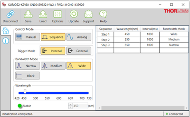
The main window of the software when the K2VB1 Selectable Bandpass Tunable Filter is connected. (When using the K2WB1(/M) or K2WL1(/M), the Narrow and Medium buttons are grayed out. For the K2XL1(/M), the Medium and Wide buttons are grayed out.)
Manual Mode
In manual mode, the center wavelength is immediately set when a command is issued. This command can be issued in several ways:
- Turn the ADJUST knob on the KURIOS2 front panel (pictured to the right).
- Use the PREV, NEXT, and ENTER buttons on the KURIOS2 front panel to toggle "WAVELENGTH", and change the value using either the ADJUST knob or the PREV and NEXT buttons.
- Use the wavelength slider in the software interface (shown in the screenshot below).
- Type the desired wavelength into the software interface.
- Issue the serial command.
The KURIOS2 controller defaults to the manual mode when it is powered on. If the controller is not in manual mode, it can be activated through any of the following methods:
- Use the PREV, NEXT, and ENTER buttons on the KURIOS2 controller's front panel to toggle "MODE", and change the selection to "MANUAL".
- Press Manual in the software interface (shown in the screenshot below).
- Issue the serial command.
Bandwidth (Item # K2VB1(/M) Only)
For the K2VB1(/M) Selectable Bandpass Tunable Filter, the bandwidth (Narrow, Medium, or Wide) can be set using any of the following methods:
- Use the PREV, NEXT, and ENTER buttons on the KURIOS2 front panel to toggle "BANDWIDTH", and change the selection to either "NARROW", "MEDIUM", or "WIDE".
- Press Narrow, Medium, or Wide in the software interface (shown in the screenshot to the below).
- Issue the proper serial commands.
Sequenced Mode
In sequenced mode, the KURIOS2 controller stores a series of center wavelengths that it sends to the optical head whenever an internal or external trigger is received. The maximum number of wavelengths that can be stored in the sequence is 1024; at the end of the sequence, the controller loops back to the beginning and starts over again. This sequence is stored within the controller's non-volatile memory, enabling the user to close the software GUI or unplug with USB cable without loss of the preloaded sequence. However, powering off the controller will cause the non-volatile memory to reset. The software is used to input the sequence of wavelengths desired. Sequenced mode can be activated using any of the following methods:
- Use the PREV, NEXT, and ENTER buttons on the KURIOS2 front panel to toggle "MODE" and change the selection to either "SEQ.INT" or "SEQ.EXT".
- Press Sequence in the software interface (shown in the screenshot to the right).
- Issue the proper serial commands.
Analog Mode
In analog mode, the center wavelength is directly controlled by a 0 to 5 V signal connected to the ANALOG IN connector on the KURIOS2 controller's back panel. A signal of 0 V corresponds to the shortest wavelength and 5 V to the longest. When an internal or external trigger is received, the center wavelength is updated to the value determined by the ANALOG IN voltage; at all other times, the ANALOG IN voltage is ignored. Analog mode can be accessed using any of the following methods:
- Use the PREV, NEXT, and ENTER buttons on the KURIOS2 front panel to toggle "MODE" and change the selection to either "ANA.INT" or "ANA.EXT".
- Press Analog in the software interface (shown in the screenshot to the right).
- Issue the proper serial commands.
Internal and External Triggering
In both sequenced and analog modes, an internal or external trigger is needed to update the center wavelength. Otherwise, the wavelength remains unchanged.
For internal triggering, the signal is provided by a clock within the controller and has a user-specified interval between triggers from 1 ms to 60 s. Moreover, when in sequenced mode, each wavelength in the sequence can have its own interval time. In contrast, when in analog mode, the controller updates the wavelength according to the analog input signal at the interval time set by the user.
For external triggering, the 5 V TTL signal is provided through the Trigger In BNC connector on the back panel. The user can choose whether the trigger occurs on the rising or falling edge of the signal.
Beam Blocking Mode
In beam blocking mode ("black mode"), the transmission is set to a minimum value, ignoring the center wavelength setting. This mode can be activated through any of the following methods:
- Use the PREV, NEXT, and ENTER buttons on the KURIOS2 front panel to toggle "BANDWIDTH" and change the selection to "BLACK".
- Press Black in the software interface (shown in the screenshot above).
- Issue the proper serial command.

Click to Enlarge
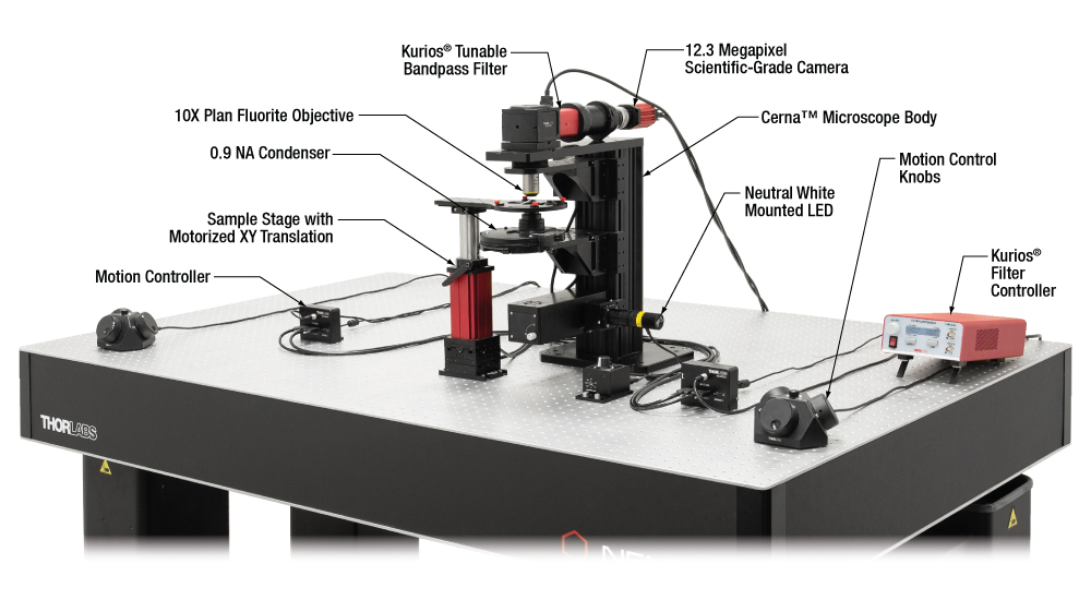
ハイパースペクトルイメージング顕微鏡の概略図
Click for Details
こちらのDIYハイパースペクトルイメージングシステムは、
当社のCerna顕微鏡プラットフォームをベースに構築されています。
主なコンポーネントはチューナブルバンドパスフィルタKURIOS-VB1(旧製品)、モノクロサイエンティフィックカメラ CS126MU、およびマウント付き白色LEDMNWHL4です。
ハイパースペクトルイメージング
ハイパースペクトルイメージングでは、波長毎に独立した2次元画像のスタックが取得されます。この手法は試料の同定と分析を素早くできるため、顕微鏡法、バイオ医学イメージング、マシンビジョンなどの用途に頻繁に使用されます。
ハイパースペクトルイメージングで得られる画像のスペクトル分解能は、カラータイプのカメラを単独で使用した場合に比べて格段に優れています。カラータイプのカメラは3種類の比較的幅広のスペクトルチャンネル(赤、緑、青)を使用して、画像のスペクトル範囲全体を表示します。これに対し、ハイパースペクトルイメージングシステムでは液晶チューナブルバンドパスフィルタや回折格子のような光学素子を用いるため、非常に狭い帯域幅のスペクトルチャンネルが得られます。
画像のスタック例
下の画像および動画はハイパースペクトルイメージング技術によるものです。図1は成熟したナズナの胚の2枚の画像で、中心波長500 nmおよび650 nmに設定したチューナブルフィルタで取得しています。これら2つの画像は、それぞれのスペクトルチャンネル毎に得られた視野全体を示しています。図2は、同じ試料の31枚の画像から構成された動画です。420 nm~730 nmの中心波長範囲について10 nm刻みで取得しています。(10 nmはスペクトル分解能ではありません。スペクトル分解能は各波長におけるFWHM帯域幅によって決まります)。図3では、各スペクトルチャンネルの画像を使用して各ピクセルの色を決定し、カラー画像を合成しています。また図3はピクセルごとに広帯域のスペクトルが得られることを示しており、それにより視野内の異なる部位の特性を分光学的に同定することができます。
Kurios®チューナブルフィルタはハイパースペクトルイメージングに多くの利点をもたらしています。角度調整タイプのフィルタを使用した場合や手動でフィルタ交換を行った場合とは異なり、Kuriosフィルタは動く部分が無いためミリ秒レベルで振動の無い波長切り替えが可能です。測定中にフィルタを動かしたり交換したりしないため、画像を登録する際にデータの「画素ずれ」も生じません。当社のフィルタにはソフトウェアと外部トリガ付きのベンチトップ型コントローラも付属しており、データ収集および分析プログラムとも容易に統合できます。
Click to Enlarge
図3:各スペクトルチャンネルで取得した視野全体の画像(図1参照)を統合して得られた、成熟したナズナの胚のカラー画像。複数のチャネルに渡ってデータを取得することで、画像内の各ピクセルのスペクトルが得られます。

Click to Enlarge
図1:異なる中心波長で取得された2枚の成熟したナズナの胚の画像。スペクトルチャンネルごとに視野全体の画像を取得しています。
図2: この動画はチューナブルフィルタKURIOS-WB1(旧製品)の中心波長ごとに取得した試料の画像を示しています。中心波長を420 nm~730 nmの範囲で10 nm刻みで増加させています(10 nmはスペクトル分解能ではありません。スペクトル分解能は各波長におけるFWHM帯域幅によって決まります)。
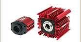
波長可変光源
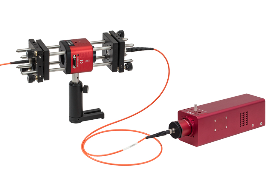
下の写真はKURIOSチューナブルフィルタと広帯域光源を用いた波長可変光源で、可視波長域(420~730 nm)においてミリ秒レベルでの波長チューニングが可能です。
Click to Enlarge
The K2WB1/M filter is connected to an SLS201L tungsten-halogen light source to create a tunable
illumination source for visible wavelengths.
Click to Enlarge
The main window of the software when the K2VB1 Selectable Bandpass Tunable Filter is connected. (When using the K2WB1(/M) or K2WL1(/M), the Narrow and Medium buttons are grayed out. For the K2XL1(/M), the Medium and Wide buttons are grayed out.)
ソフトウェア
バージョン1.9.6
Kurios制御用のGUIならびに制御に必要なドライバやC/C++のコード例、LabVIEW VIを含みます。ダウンロードするには下記のボタンをクリックしてください。

Kurios®ソフトウェアパッケージ
GUIインターフェイス
Kuriosソフトウェアパッケージでは、フィルターヘッドの中心波長を決定するモードをマニュアルモード、シーケンスモード、アナログモードから選択できます(各モードの詳細については「制御」タブをご覧ください)。マニュアルモードでは、波長スライダが使用可能で、420~730 nm、430~730 nmまたは650~1100 nmの範囲内で中心波長を選択することが可能です。シーケンスモードならびにアナログモードでは、内部トリガまたは外部トリガを選択することができます。中心波長を更新するためにはトリガが必要です。
シーケンスモードならびにアナログモードでは、コントローラによって繰り返される最大1024個の波長のシーケンスを定義することができます。シーケンスの各ステップでは波長と持続時間(1 ms~60 s)が決まっています。シーケンスは「Save Profile」ならびに「Load Profile」ボタンを使用して、CSV形式で保存と読み込みができます。
カスタムソフトウェアの開発
当社では、KuriosコントローラのUSBポートを介してほかの機器から制御できるよう、C/C++ならびにLabVIEWによるソフトウェア開発キットもご提供しております。C++のコードとLabVIEWによるプログラムのサンプルにより、C言語のコマンドとLabVIEWのVIがどのように使われるかが分かります。
| Damage Threshold Specifications | ||
|---|---|---|
| Item # Suffix | Laser Type | Damage Threshold |
| -WB1/M -WL1(/M) -XL1(/M) |
Pulsed (ns) | 0.1 J/cm2 |
| Pulsed (fs) | 0.02 J/cm2 (532 nm, 76 Hz, 100 fs, Ø162 µm) | |
| CWa | 0.8 W/cm (532 nm, Ø0.471 mm) | |
Damage Threshold Data for Kurios® Tunable Bandpass Filters
The specifications to the right are measured data for Thorlabs' Kurios Tunable Filters.
レーザによる損傷閾値について
このチュートリアルでは、レーザ損傷閾値がどのように測定され、使用する用途に適切な光学素子の決定にその値をどのようにご利用いただけるかを総括しています。お客様のアプリケーションにおいて、光学素子を選択する際、光学素子のレーザによる損傷閾値(Laser Induced Damage Threshold :LIDT)を知ることが重要です。光学素子のLIDTはお客様が使用するレーザの種類に大きく依存します。連続(CW)レーザは、通常、吸収(コーティングまたは基板における)によって発生する熱によって損傷を引き起こします。一方、パルスレーザは熱的損傷が起こる前に、光学素子の格子構造から電子が引き剥がされることによって損傷を受けます。ここで示すガイドラインは、室温で新品の光学素子を前提としています(つまり、スクラッチ&ディグ仕様内、表面の汚染がないなど)。光学素子の表面に塵などの粒子が付くと、低い閾値で損傷を受ける可能性があります。そのため、光学素子の表面をきれいで埃のない状態に保つことをお勧めします。光学素子のクリーニングについては「光学素子クリーニングチュートリアル」をご参照ください。
テスト方法
当社のLIDTテストは、ISO/DIS 11254およびISO 21254に準拠しています。
初めに、低パワー/エネルギのビームを光学素子に入射します。その光学素子の10ヶ所に1回ずつ、設定した時間(CW)またはパルス数(決められたprf)、レーザを照射します。レーザを照射した後、倍率約100倍の顕微鏡を用いた検査で確認し、すべての確認できる損傷を調べます。特定のパワー/エネルギで損傷のあった場所の数を記録します。次に、そのパワー/エネルギを増やすか減らすかして、光学素子にさらに10ヶ所レーザを照射します。このプロセスを損傷が観測されるまで繰返します。損傷閾値は、光学素子が損傷に耐える、損傷が起こらない最大のパワー/エネルギになります。1つのミラーBB1-E02の試験結果は以下のようなヒストグラムになります。
上の写真はアルミニウムをコーティングしたミラーでLIDTテストを終えたものです。このテストは、損傷を受ける前のレーザのエネルギは0.43 J/cm2 (1064 nm、10 ns pulse、 10 Hz、Ø1.000 mm)でした。
| Example Test Data | |||
|---|---|---|---|
| Fluence | # of Tested Locations | Locations with Damage | Locations Without Damage |
| 1.50 J/cm2 | 10 | 0 | 10 |
| 1.75 J/cm2 | 10 | 0 | 10 |
| 2.00 J/cm2 | 10 | 0 | 10 |
| 2.25 J/cm2 | 10 | 1 | 9 |
| 3.00 J/cm2 | 10 | 1 | 9 |
| 5.00 J/cm2 | 10 | 9 | 1 |
試験結果によれば、ミラーの損傷閾値は 2.00 J/cm2 (532 nm、10 ns pulse、10 Hz、 Ø0.803 mm)でした。尚、汚れや汚染によって光学素子の損傷閾値は大幅に低減されるため、こちらの試験はクリーンな光学素子で行っています。また、特定のロットのコーティングに対してのみ試験を行った結果ではありますが、当社の損傷閾値の仕様は様々な因子を考慮して、実測した値よりも低めに設定されており、全てのコーティングロットに対して適用されています。
CWレーザと長パルスレーザ
光学素子がCWレーザによって損傷を受けるのは、通常バルク材料がレーザのエネルギを吸収することによって引き起こされる溶解、あるいはAR(反射防止)コーティングのダメージによるものです[1]。1 µsを超える長いパルスレーザについてLIDTを論じる時は、CWレーザと同様に扱うことができます。
パルス長が1 nsと1 µs の間のときは、損傷は吸収、もしくは絶縁破壊のどちらかで発生していると考えることができます(CWとパルスのLIDT両方を調べなければなりません)。吸収は光学素子の固有特性によるものか、表面の不均一性によるものかのどちらかによって起こります。従って、LIDTは製造元の仕様以上の表面の質を有する光学素子にのみ有効です。多くの光学素子は、ハイパワーCWレーザで扱うことができる一方、アクロマティック複レンズのような接合レンズやNDフィルタのような高吸収光学素子は低いCWレーザ損傷閾値になる傾向にあります。このような低い損傷閾値は接着剤や金属コーティングにおける吸収や散乱によるものです。
線形パワー密度におけるLIDTに対するパルス長とスポットサイズ。長パルス~CWでは線形パワー密度はスポットサイズにかかわらず一定です。 このグラフの出典は[1]です。

繰返し周波数(prf)の高いパルスレーザは、光学素子に熱的損傷も引き起こします。この場合は吸収や熱拡散率のような因子が深く関係しており、残念ながらprfの高いレーザが熱的影響によって光学素子に損傷を引き起こす場合の信頼性のあるLIDTを求める方法は確立されておりません。prfの大きいビームでは、平均出力およびピークパワーの両方を等しいCW出力と比較する必要があります。また、非常に透過率の高い材料では、prfが上昇してもLIDTの減少は皆無かそれに近くなります。
ある光学素子の固有のCWレーザの損傷閾値を使う場合には、以下のことを知る必要があります。
- レーザの波長
- ビーム径(1/e2)
- ビームのおおよその強度プロファイル(ガウシアン型など)
- レーザのパワー密度(トータルパワーをビームの強度が1/e2の範囲の面積で割ったもの)
ビームのパワー密度はW/cmの単位で計算します。この条件下では、出力密度はスポットサイズとは無関係になります。つまり、スポットサイズの変化に合わせてLIDTを計算し直す必要がありません(右グラフ参照)。平均線形パワー密度は、下の計算式で算出できます。
ここでは、ビーム強度プロファイルは一定であると仮定しています。次に、ビームがホットスポット、または他の不均一な強度プロファイルの場合を考慮して、おおよその最大パワー密度を計算する必要があります。ご参考までに、ガウシアンビームのときはビームの強度が1/e2の2倍のパワー密度を有します(右下図参照)。
次に、光学素子のLIDTの仕様の最大パワー密度を比較しましょう。損傷閾値の測定波長が光学素子に使用する波長と異なっている場合には、その損傷閾値は適宜補正が必要です。おおよその目安として参考にできるのは、損傷閾値は波長に対して比例関係であるということです。短い波長で使う場合、損傷閾値は低下します(つまり、1310 nmで10 W/cmのLIDTならば、655 nmでは5 W/cmと見積もります)。
この目安は一般的な傾向ですが、LIDTと波長の関係を定量的に示すものではありません。例えば、CW用途では、損傷はコーティングや基板の吸収によってより大きく変化し、必ずしも一般的な傾向通りとはなりません。上記の傾向はLIDT値の目安として参考にしていただけますが、LIDTの仕様波長と異なる場合には当社までお問い合わせください。パワー密度が光学素子の補正済みLIDTよりも小さい場合、この光学素子は目的の用途にご使用いただけます。
当社のウェブ上の損傷閾値の仕様と我々が行った実際の実験の値の間にはある程度の差があります。これはロット間の違いによって発生する誤差を許容するためです。ご要求に応じて、当社は個別の情報やテスト結果の証明書を発行することもできます。損傷解析は、類似した光学素子を用いて行います(お客様の光学素子には損傷は与えません)。試験の費用や所要時間などの詳細は、当社までお問い合わせください。
パルスレーザ
先に述べたように、通常、パルスレーザはCWレーザとは異なるタイプの損傷を光学素子に引き起こします。パルスレーザは損傷を与えるほど光学素子を加熱しませんが、光学素子から電子をひきはがします。残念ながら、お客様のレーザに対して光学素子のLIDTの仕様を照らし合わせることは非常に困難です。パルスレーザのパルス幅に起因する光学素子の損傷には、複数の形態があります。以下の表中のハイライトされた列は当社の仕様のLIDT値が当てはまるパルス幅に対する概要です。
パルス幅が10-9 sより短いパルスについては、当社の仕様のLIDT値と比較することは困難です。この超短パルスでは、多光子アバランシェ電離などのさまざまなメカニクスが損傷機構の主流になります[2]。対照的に、パルス幅が10-7 sと10-4 sの間のパルスは絶縁破壊、または熱的影響により光学素子の損傷を引き起こすと考えられます。これは、光学素子がお客様の用途に適しているかどうかを決定するために、レーザービームに対してCWとパルス両方による損傷閾値を参照しなくてはならないということです。
| Pulse Duration | t < 10-9 s | 10-9 < t < 10-7 s | 10-7 < t < 10-4 s | t > 10-4 s |
|---|---|---|---|---|
| Damage Mechanism | Avalanche Ionization | Dielectric Breakdown | Dielectric Breakdown or Thermal | Thermal |
| Relevant Damage Specification | No Comparison (See Above) | Pulsed | Pulsed and CW | CW |
お客様のパルスレーザに対してLIDTを比較する際は、以下のことを確認いただくことが重要です。
エネルギ密度におけるLIDTに対するパルス長&スポットサイズ。短パルスでは、エネルギ密度はスポットサイズにかかわらず一定です。このグラフの出典は[1]です。
- レーザの波長
- ビームのエネルギ密度(トータルエネルギをビームの強度が1/e2の範囲の面積で割ったもの)
- レーザのパルス幅
- パルスの繰返周波数(prf)
- 実際に使用するビーム径(1/e2 )
- ビームのおおよその強度プロファイル(ガウシアン型など)
ビームのエネルギ密度はJ/cm2の単位で計算します。右のグラフは、短パルス光源には、エネルギ密度が適した測定量であることを示しています。この条件下では、エネルギ密度はスポットサイズとは無関係になります。つまり、スポットサイズの変化に合わせてLIDTを計算し直す必要がありません。ここでは、ビーム強度プロファイルは一定であると仮定しています。ここで、ビームがホットスポット、または他の不均一な強度プロファイルの場合を考慮して、おおよその最大パワー密度を計算する必要があります。ご参考までに、ガウシアンビームのときは一般にビームの強度が1/e2のときの2倍のパワー密度を有します。
次に、光学素子のLIDTの仕様と最大エネルギ密度を比較しましょう。損傷閾値の測定波長が光学素子に使用する波長と異なっている場合には、その損傷閾値は適宜補正が必要です[3]。経験則から、損傷閾値は波長に対して以下のような平方根の関係であるということです。短い波長で使う場合、損傷閾値は低下します(例えば、1064 nmで 1 J/cm2のLIDTならば、532 nmでは0.7 J/cm2と計算されます)。
波長を補正したエネルギ密度を得ました。これを以下のステップで使用します。
ビーム径は損傷閾値を比較する時にも重要です。LIDTがJ/cm2の単位で表される場合、スポットサイズとは無関係になりますが、ビームサイズが大きい場合、LIDTの不一致を引き起こす原因でもある不具合が、より明らかになる傾向があります[4]。ここで示されているデータでは、LIDTの測定には<1 mmのビーム径が用いられています。ビーム径が5 mmよりも大きい場合、前述のようにビームのサイズが大きいほど不具合の影響が大きくなるため、LIDT (J/cm2)はビーム径とは無関係にはなりません。
次に、パルス幅について補正します。パルス幅が長くなるほど、より大きなエネルギに光学素子は耐えることができます。パルス幅が1~100 nsの場合の近似式は以下のようになります。
お客様のレーザのパルス幅をもとに、光学素子の補正されたLIDTを計算するのにこの計算式を使います。お客様の最大エネルギ密度が、この補正したエネルギ密度よりも小さい場合、その光学素子はお客様の用途でご使用いただけます。ご注意いただきたい点は、10-9 s と10-7 sの間のパルスにのみこの計算が使えることです。パルス幅が10-7 sと10-4 sの間の場合には、CWのLIDTも調べなければなりません。
当社のウェブ上の損傷閾値の仕様と我々が行った実際の実験の値の間にはある程度の差があります。これはロット間の違いによって発生する誤差を許容するためです。ご要求に応じて、当社では個別のテスト情報やテスト結果の証明書を発行することも可能です。詳細は、当社までお問い合わせください。
[1] R. M. Wood, Optics and Laser Tech. 29, 517 (1997).
[2] Roger M. Wood, Laser-Induced Damage of Optical Materials (Institute of Physics Publishing, Philadelphia, PA, 2003).
[3] C. W. Carr et al., Phys. Rev. Lett. 91, 127402 (2003).
[4] N. Bloembergen, Appl. Opt. 12, 661 (1973).

レーザーシステムが光学素子に損傷を引き起こすかどうか判断するプロセスを説明するために、レーザによって引き起こされる損傷閾値(LIDT)の計算例をいくつかご紹介します。同様の計算を実行したい場合には、右のボタンをクリックしてください。計算ができるスプレッドシートをダウンロードいただけます。ご使用の際には光学素子のLIDTの値と、レーザーシステムの関連パラメータを緑の枠内に入力してください。スプレッドシートでCWならびにパルスの線形パワー密度、ならびにパルスのエネルギ密度を計算できます。これらの値はスケーリング則に基づいて、光学素子のLIDTの調整スケール値を計算するのに用いられます。計算式はガウシアンビームのプロファイルを想定しているため、ほかのビーム形状(均一ビームなど)には補正係数を導入する必要があります。 LIDTのスケーリング則は経験則に基づいていますので、確度は保証されません。なお、光学素子やコーティングに吸収があると、スペクトル領域によってLIDTが著しく低くなる場合があります。LIDTはパルス幅が1ナノ秒(ns)未満の超短パルスには有効ではありません。
ガウシアンビームの最大強度は均一ビームの約2倍です。
CWレーザの例
波長1319 nm、ビーム径(1/e2)10 mm、パワー0.5 Wのガウシアンビームを生成するCWレーザーシステム想定します。このビームの平均線形パワー密度は、全パワーをビーム径で単純に割ると0.5 W/cmとなります。
しかし、ガウシアンビームの最大パワー密度は均一ビームの約2倍です(右のグラフ参照)。従って、システムのより正確な最大線形パワー密度は1 W/cmとなります。
アクロマティック複レンズAC127-030-CのCW LIDTは、1550 nmでテストされて350 W/cmとされています。CWの損傷閾値は通常レーザ光源の波長に直接スケーリングするため、LIDTの調整値は以下のように求められます。
LIDTの調整値は350 W/cm x (1319 nm / 1550 nm) = 298 W/cmと得られ、計算したレーザーシステムのパワー密度よりも大幅に高いため、この複レンズをこの用途に使用しても安全です。
ナノ秒パルスレーザの例:パルス幅が異なる場合のスケーリング
出力が繰返し周波数10 Hz、波長355 nm、エネルギ1 J、パルス幅2 ns、ビーム径(1/e2)1.9 cmのガウシアンビームであるNd:YAGパルスレーザーシステムを想定します。各パルスの平均エネルギ密度は、パルスエネルギをビームの断面積で割って求めます。
上で説明したように、ガウシアンビームの最大エネルギ密度は平均エネルギ密度の約2倍です。よって、このビームの最大エネルギ密度は約0.7 J/cm2です。
このビームのエネルギ密度を、広帯域誘電体ミラーBB1-E01のLIDT 1 J/cm2、そしてNd:YAGレーザーラインミラーNB1-K08のLIDT 3.5 J/cm2と比較します。LIDTの値は両方とも、波長355 nm、パルス幅10 ns、繰返し周波数10 Hzのレーザで計測しました。従って、より短いパルス幅に対する調整を行う必要があります。 1つ前のタブで説明したようにナノ秒パルスシステムのLIDTは、パルス幅の平方根にスケーリングします:
この調整係数により広帯域誘電体ミラーBB1-E01のLIDTは0.45 J/cm2に、Nd:YAGレーザーラインミラーのLIDTは1.6 J/cm2になり、これらをビームの最大エネルギ密度0.7 J/cm2と比較します。広帯域ミラーはレーザによって損傷を受ける可能性があり、より特化されたレーザーラインミラーがこのシステムには適していることが分かります。
ナノ秒パルスレーザの例:波長が異なる場合のスケーリング
波長1064 nm、繰返し周波数2.5 Hz、パルスエネルギ100 mJ、パルス幅10 ns、ビーム径(1/e2)16 mmのレーザ光を、NDフィルタで減衰させるようなパルスレーザーシステムを想定します。これらの数値からガウシアン出力における最大エネルギ密度は0.1 J/cm2になります。Ø25 mm、OD 1.0の反射型NDフィルタ NDUV10Aの損傷閾値は355 nm、10 nsのパルスにおいて0.05 J/cm2で、同様の吸収型フィルタ NE10Aの損傷閾値は532 nm、10 nsのパルスにおいて10 J/cm2です。1つ前のタブで説明したように光学素子のLIDTは、ナノ秒パルス領域では波長の平方根にスケーリングします。
スケーリングによりLIDTの調整値は反射型フィルタでは0.08 J/cm2、吸収型フィルタでは14 J/cm2となります。このケースでは吸収型フィルタが光学損傷を防ぐには適した選択肢となります。
マイクロ秒パルスレーザの例
パルス幅1 µs、パルスエネルギ150 µJ、繰返し周波数50 kHzで、結果的にデューティーサイクルが5%になるレーザーシステムについて考えてみます。このシステムはCWとパルスレーザの間の領域にあり、どちらのメカニズムでも光学素子に損傷を招く可能性があります。レーザーシステムの安全な動作のためにはCWとパルス両方のLIDTをレーザーシステムの特性と比較する必要があります。
この比較的長いパルス幅のレーザが、波長980 nm、ビーム径(1/e2)12.7 mmのガウシアンビームであった場合、線形パワー密度は5.9 W/cm、1パルスのエネルギ密度は1.2 x 10-4 J/cm2となります。これをポリマーゼロオーダ1/4波長板WPQ10E-980のLIDTと比較してみます。CW放射に対するLIDTは810 nmで5 W/cm、10 nsパルスのLIDTは810 nmで5 J/cm2です。前述同様、光学素子のCW LIDTはレーザ波長と線形にスケーリングするので、CWの調整値は980 nmで6 W/cmとなります。一方でパルスのLIDTはレーザ波長の平方根とパルス幅の平方根にスケーリングしますので、1 µsパルスの980 nmでの調整値は55 J/cm2です。光学素子のパルスのLIDTはパルスレーザのエネルギ密度よりはるかに大きいので、個々のパルスが波長板を損傷することはありません。しかしレーザの平均線形パワー密度が大きいため、高出力CWビームのように光学素子に熱的損傷を引き起こす可能性があります。
| Posted Comments: | |
inkwon Yoon
(posted 2023-11-29 10:57:35.407) Hello, I'm currently using Kurios-WB1/M, and I was wondering if you could provide guidance on how to automate it using MATLAB. Thank you.
Best regards,
Thor labs cdolbashian
(posted 2023-12-13 03:18:47.0) Thank you for contacting Thorlabs! We currently have a demo project that we can share with you. We will reach out to you directly by email. Dang Nguyen Hai
(posted 2023-11-02 16:43:52.283) Dear Sir/Madam
Firstly, I would like to introduce about us. MTEC Co., Ltd.
We are a distributor for some brand such as: Tektronix - Fluke - Keithley - Hioki - Sanwa - Ametek - Emtest - Elit - Bristol Instruments... in Vietnam.
Currently, Our strategy client need your Kurios WL1(/M) device.
Quantity: 1 set
Please send me your best quote and data sheet for this equipment and its accessories.
Let me know exactly Country of Origin of all Goods
Contact: (+84) 818 020781
sales3@mtec.com.vn cdolbashian
(posted 2023-11-02 12:45:47.0) Thank you for reaching out to us with this quote request! I have reached out to you with such details, and further contact information on your local distributor which would be able to fulfill this order. Mutian Zhuang
(posted 2023-09-21 10:30:10.067) Could you make the Tunable infrared filters work in 1000 to 1700 nm? cdolbashian
(posted 2023-10-02 04:20:11.0) Thank you for contacting Thorlabs. We greatly appreciate hearing from our customers concerning possible extensions to our product lines. Currently, we are in the process of expanding our KURIOS offerings, and an IR tunable filter is on our roadmap. Thorlabs has an internal forum where product ideas can be posted. I will be sure to add your requirement to that list in the hopes that it will expedite the development progress. For future custom requests, please feel free to contact your local Tech Support team (in your case: techsupport@thorlabs.com). user
(posted 2021-11-18 12:52:01.01) 您好,目前我们正在使用KURIOS-XL1这款产品,希望能够搭建一个多光谱偏振成像系统,在实际应用过程中将一个普通科研相机放置于滤波器后无法成像(画面漆黑一片),请问这可能是什么原因造成的呢?有什么解决办法吗?如果方便的话,可以请负责这方面的技术人员联系我详谈吗。 YLohia
(posted 2021-11-23 02:04:52.0) Thank you for contacting Thorlabs. An applications engineer from our team in China (techsupport-cn@thorlabs.com) has reached out to you directly. Kinjiro Amano
(posted 2021-04-14 06:26:55.773) Could I have the information about the resolution of wavelength? Would it be posslbiel to tune the band at every 10nm?
Would it be possible to make the spectral range wider. e.g. 400-730nm? YLohia
(posted 2021-04-19 03:48:52.0) Thank you for contacting Thorlabs. KURIOS' center wavelength resolution is 1nm. Unfortunately, it is not possible to tune the bandpass width every 10 nm because it is wavelength-dependent and increases linearly with wavelength. Please see the performance plots displayed below. We cannot offer a 400-730 nm range option for this device at the moment. Gianrico Filacchione
(posted 2021-02-08 03:45:31.81) Good morning,
I'm interested to procure a Kurios-WL1 liquid crystal tunable filter to be employed in a remote sensing instrument breadboard. Before proceeding with the order, I need to understand filter's performances when used in a converging optical beam configuration, e.g. when the filter is placed between a telescope and a detector. I'm asking this because from Thorlabs documentation and given examples seems that the filter performances refer to collimated optical beam (parallel rays). Can you please clarify me this point? The FOV=+/-6° specification is applicable also to converging optical beams?
Thank you for your feedback.
Best regards,
Gianrico Filacchione
INAF-IAPS, Rome, IT
phone: +39-0645488454
gianrico.filacchione@inaf.it YLohia
(posted 2021-02-09 09:42:44.0) Hello Gianrico, thank you for contacting Thorlabs. This specification is also applicable to converging optical beams. The wider FOV would result in a non-uniform image. To achieve a better image quality, you may want to use the KURIOS with a longer focal length relay lens (narrower FOV). We have reached out to you directly to discuss this further. Frederic Bourson
(posted 2020-10-08 05:27:41.167) In the specifications, the tuning acuracy is given to be +/-FWHM/10 so, about +/- 2nm.
Could you please tell me if this value corresponds to the repetability of the repositioning or to a possible bias between the setpoint and the central wavelength of the filter. By "repeatability of the positioning", I mean the accuracy of the repositionning after a change in wavelength?
Thank you in advance YLohia
(posted 2020-10-12 09:28:39.0) Thank you for contacting Thorlabs. The tuning accuracy specs refers to the error between the set wavelength and the actual pass-band wavelength of the filter during operation. The repeatability is around 1-2 nm. Nick Anthony
(posted 2020-01-06 15:44:04.517) How can I reset back to the beginning of a sequence? For example: When using an externally triggered sequence if I load a sequence of 100 wavelengths and then let the sequence run up to the 50th item, how do I make the sequence start at the 1st item again for the next run. I have tried deleting the sequence and loading a new one but I have found that when I run the sequence again it will still start at the 51st item of the sequence. nbayconich
(posted 2020-01-08 01:51:30.0) Thank you for contacting Thorlabs and thank you for reporting this issue we were not aware of. The internal sequence buffer stores the next immediate wavelength which might have already been deleted, but it is not cleared in time. We are now working on fixing this.
At this stage, you may temporarily switch back to manual mode to do so. If you are using the Kurios software, you may switch the operating mode to manual before importing the new sequence; if you are using serial commands, you may use the command "OM=1" to switch the operating mode to manual before inserting new sequence. You may also use to chapter 5.3 of the Kurios manual as a reference for the command list. We will reach out to you via email with more information. Nick Anthony
(posted 2019-12-19 18:52:32.043) I am trying to replace some old `Varispec` LCTFs with the Kurios-VB1 but I am getting very poor imaging performance compared to the old LCTF model. Can you please contact me so I can provide example images and a better description of my optical set up? nbayconich
(posted 2020-01-15 09:03:27.0) Thank you for contacting Thorlabs and providing us your optical setup and results via email. The "Angle of Incidence (Field of View)" for Kurios-VB1 is +/-6 degree. The larger field of view of the Varispec model may be the cause of the difference in performance you are observing. To achieve better image quality you may try to use the KURIOS with a longer focal length relay lens such as 200mm for a more uniform image. ikhwan8327
(posted 2018-08-15 05:22:17.62) Hi I have a question about running Kurios-VB1 in MATLAB
I want to know that "how to control the Kurios in MATLAB"
I thought that MATLAB could involved the c++ code (uart_library.h and uart_library_ftdi64.dll) library using "loadlibray" function. However it was failed.
Best regards YLohia
(posted 2018-09-17 09:59:58.0) Hello, thank you for contacting Thorlabs. While we currently do not fully support MATLAB for this product line, we do have a demo project that we can provide. We tried reaching out to you directly with this information, but it looks like the email you provided had a typo. Please reach out to techsupport@thorlabs.com for a follow up. christoph.eckert
(posted 2017-10-02 14:09:15.153) Is it possible that the CW Damage Threshold value 0.8W/cm has to be squared ?
Like 0.8W/cm^2
Best regards tfrisch
(posted 2017-10-02 12:45:29.0) Hello, thank you for contacting Thorlabs. While the areal power density (in units of watts per square centimeter) is the natural way of thinking about thermal damage, this does not scale well over different regimes of beam size. Rather linear power density (power over diameter) does, so we have been working on changing our LIDT data over to that. More details on this can be found on the damage threshold tab: https://www.thorlabs.us/newgrouppage9.cfm?objectgroup_id=3488&tabname=Damage%20Thresholds dominique.guilhem
(posted 2017-08-02 14:41:38.357) For multispectral infrared thermography I am looking for variable interference filter (Delta-lambda ~ 0.1 to 0.5 µm) working within the band 3 to 5 µm (or a portion of this spectrum).
Does it exists some parts like that in your catalog of products ?
If not do you know where to look for it ? tfrisch
(posted 2017-08-16 11:36:18.0) Hello, thank you for contacting Thorlabs. I have posted your need for an IR tunable filter in our internal engineering forum, and I will reach out to you directly to discuss your application. lhj
(posted 2015-03-18 08:18:19.073) Dear sirs
Presently usuing this liquid crystal Tunable Filetr I hope to make a hyperspectral imaging system.
If the KURIOS-WB1 attached on general CMOS camera (not attached on microscope), can I get useful image?
Thanks in advance.
Hyang Jin Lee
iNexus,inc. jlow
(posted 2015-03-20 09:10:16.0) Response from Jeremy at Thorlabs: We will contact you directly to discuss your application in more detail. user
(posted 2014-06-11 16:29:01.703) What was the coupling ratio of fiber to fiber in the picture of Application Idea. myanakas
(posted 2014-06-11 11:35:13.0) Response from Mike at Thorlabs: Thank you for your feedback. There is not one answer to this question as there are many variables involved. Assuming that we collimate most of the input power that was coupled from the SLS201 broadband light source, the efficiency after this point will vary depending on the selected wavelength from the broadband source. Approximately 85-90% of that light will make it through the FGS900M. For maximum transmission KURIOS-WB1 the input light should be polarized along the transmission axis which is marked using white witness lines. Being unpolarized here we will transmit approximately 50% of the input light. From here the efficiency will be solely dependent on the wavelength chosen using the KURIOS-WB1 and the amount of power you white light source had at tat wavelength. The plot in the overview tab shows the percentage of light that will be transmitted at a certain wavelength by the KURIOS filter. From here the final factor is the coupling efficiency of the output collimation package into the output fiber. This will also vary by the wavelength chosen. If you estimate these losses, just to give an idea of the efficiency for the system, you will get about 20% efficiency. The coupling efficiency of the system will vary based on the wavelength and the source power distribution. |

 ズーム
ズーム| Performance Plots (Click for Plot) | ||
|---|---|---|
| Item # | K2WB1(/M) | K2WL1(/M) |
| Transmission Spectruma |  |
 |
| Bandwidthb |  |
 |
| Transmission at Center Wavelengtha | ||
| Optical Density, CWL = 625 nm |  |
 |
| Switching Timec |  |
 |
| Uniformity,d CWL = 550 nm |  |
 |
| Raw Data for All Plots | K2WB1(/M) | K2WL1(/M) |
- Wavelength Range: 420 - 730 nm
- Bandwidth at λ = 550 nm: 35 nm FWHM
- Switching Time: <150 ms
- Polarized Transmission at λ = 550 nm: 45%
- Requires the KURIOS2 Controller (Sold Separately Below)
- See the Table to the Right and the Specs Tab Above for More Details
K2WB1(/M) and K2WL1(/M) are fixed, wide-bandpass versions of our Kurios tunable bandpass filters. The center wavelength (CWL) is tunable from 420 nm to 730 nm. The performance plots to the right show that the transmission and width of the bandpass region vary over the specified wavelength range.
To eliminate transmission in the near-IR and IR wavelength range, each of these tunable filters includes a hard-coated shortpass filter with a 750 nm cut-off wavelength in an SM-threaded housing. This filter is recommended for use at the incident side of the filter head to protect the internal components from excessive IR exposure. The K2WB1(/M) includes the FESH0750 filter and the K2WL1(/M) includes a Ø2" version of the FESH0750 filter with the same optical properties. The filter also blocks UV light (<385 nm) and may be used to reduce UV intensity in the incident beam.
The fixed bandpass tunable filters provide switching times that vary depending upon the initial and final wavelengths. As shown in the contour plots in the table to the right, for small changes in the CWL (Δλ ≤ 30 nm), the switching time will be ≤75 ms. For greater changes in the CWL, the switching time will increase, reaching a maximum of 150 ms when switching over the full wavelength range.
The K2WB1(/M) has a clear aperture of Ø20 mm. The housing has internal SM1 (1.035"-40) threading and is compatible with our 30 mm cage systems. Alternatively, the K2WL1(/M) has a clear aperture of Ø35 mm. Its housing has internal SM2 (2.035"-40) threading and is compatible with our 60 mm cage systems.
The K2WB1(/M) and K2WL1(/M) filters require the KURIOS2 controller for operation (sold separately below). Each filter is factory calibrated and ships with a switching time map so that users may optimize their system for the specific filter. The map can be saved to disk through the included Windows® software.

 ズーム
ズーム| K2XL1(/M) Performance Plots (Click for Plot) | |
|---|---|
| Transmission Spectruma |  |
| Bandwidthb |  |
| Transmission at Center Wavelengtha | |
| Optical Density, CWL = 625 nm |  |
| Switching Timec |  |
| Uniformity,d CWL = 550 nm |  |
| Raw Data for All Plots | |
- Wavelength Range: 430 - 730 nm
- Bandwidth at λ = 550 nm: 10 nm FWHM
- Switching Time: <250 ms
- Polarized Transmission at λ = 550 nm: 17%
- Requires the KURIOS2 Controller (Sold Separately Below)
- See the Table to the Right and the Specs Tab Above for More Details
K2XL1(/M) is a fixed, narrow-bandpass version of our Kurios tunable bandpass filters. The center wavelength (CWL) is tunable from 430 nm to 730 nm. The performance plots to the right show that the transmission and width of the bandpass region vary over the specified wavelength range.
To eliminate transmission in the near-IR and IR wavelength range, this tunable filter includes a Ø2" version of the FESH0750 hard-coated shortpass filter with a 750 nm cut-off wavelength in an SM2-threaded housing. This filter is recommended for use at the incident side of the filter head to protect the internal components from excessive IR exposure. The filter also blocks UV light (<385 nm) and may be used to reduce UV intensity in the incident beam.
The fixed narrow bandpass tunable filter provides switching times that vary depending upon the initial and final wavelengths. As shown in the contour plot in the table to the right, for small changes in the CWL (Δλ ≤ 30 nm), the switching time will be ≤120 ms. For greater changes in the CWL, the switching time will increase, reaching a maximum of 250 ms when switching over the full wavelength range.
The K2XL1(/M) has a clear aperture of Ø35 mm. Its housing has internal SM2 (2.035"-40) threading and is compatible with our 60 mm cage systems.
The K2XL1(/M) filters require the KURIOS2 controller for operation (sold separately below). Each filter is factory calibrated and ships with a switching time map so that users may optimize their system for the specific filter. The map can be saved to disk through the included Windows® software.

 ズーム
ズーム| K2XE2(/M) Performance Plots (Click for Plot) | |
|---|---|
| Transmission Spectruma |  |
| Bandwidthb |  |
| Transmission at Center Wavelengtha | |
| Optical Density, CWL = 850 nm |  |
| Switching Timec |  |
| Uniformity,d CWL = 850 nm |  |
| Raw Data for All Plots | |
- Wavelength Range: 650 - 1100 nm
- Bandwidth at λ = 850 nm: 17 nm FWHM
- Switching Time: <760 ms
- Polarized Transmission at λ = 850 nm: 44%
- Requires the KURIOS2 Controller (Sold Separately Below)
- See the Table to the Right and the Specs Tab Above for More Details
K2XE2(/M) is a fixed, bandpass Kurios tunable bandpass filter for near-IR wavelengths. The center wavelength (CWL) is tunable from 650 nm to 1100 nm.
The fixed bandpass tunable filters provide switching times that vary depending upon the initial and final wavelengths. As shown in the contour plot in the table to the right, for small changes in the CWL (Δλ ≤ 30 nm), the switching time will be ≤200 ms. For greater changes in the CWL, the switching time will increase, reaching a maximum of 760 ms when switching over the full wavelength range.
The K2XE2(/M) has a clear aperture of Ø20 mm. The housing has internal SM1 (1.035"-40) threading and is compatible with our 30 mm cage systems.
The K2XE2(/M) filters require the KURIOS2 controller for operation (sold separately below). Each filter is factory calibrated and ships with a switching time map so that users may optimize their system for the specific filter. The map can be saved to disk through the included Windows® software.

 ズーム
ズーム| K2VB1(/M) Performance Plots (Click for Plot) | |||
|---|---|---|---|
| Setting | Narrow | Medium | Wide |
| Transmission Spectruma |  |
 |
 |
| Bandwidthb |  |
||
| Transmission at Center Wavelengtha | |||
| Optical Density, CWL = 625 nm |  |
||
| Spectrum at 625 nm |  |
||
| Switching Timec |  |
 |
 |
| Uniformity,d CWL = 550 nm |  |
 |
 |
| Raw Data for All Plots | |||
- Wavelength Range: 420 - 730 nm
- Bandwidth at λ = 550 nm:
- Narrow Setting: 10 nm FWHM
- Medium Setting: 18 nm FWHM
- Wide Setting: 32 nm FWHM
- Switching Time Depends Upon Bandwidth and Initial and Final Wavelength:
- Narrow Setting: <750 ms
- Medium Setting: <500 ms
- Wide Setting: <250 ms
- Polarized Transmission at λ = 550 nm:
- Narrow Setting: 13%
- Medium Setting: 17%
- Wide Setting: 20%
- Requires the KURIOS2 Controller (Sold Separately Below)
- See the Table to the Right and the Specs Tab Above for More Details
K2VB1(/M) is the selectable bandpass version of our Kurios tunable bandpass filters. The center wavelength (CWL) is tunable from 420 nm to 730 nm, and the user may set a bandwidth of Narrow, Medium, or Wide. The performance plots to the right show that the transmission and width of the bandpass region vary over the specified wavelength range.
To eliminate transmission in the near-IR and IR wavelength ranges, an FESH0750 Hard-Coated Shortpass Filter is included. This filter has a 750 nm cut-off wavelength, is mounted in an SM1-threaded (1.035"-40) housing, and is recommended for use at the incident side of the filter head to protect the internal components from excessive IR exposure. The filter also blocks UV light (<385 nm) and may be used to reduce UV intensity in the incident beam.
The switching time of the selectable bandpass Kurios depends upon the bandwidth setting and the initial and final wavelengths. The maximum switching time is 750 ms for the Narrow setting, 500 ms for the Medium setting, and 250 ms for the Wide setting. In general, the switching time will be longer for greater changes in wavelength.
The K2VB1(/M) filters require the KURIOS2 controller for operation (sold separately below). Each filter is factory calibrated and ships with a switching time map so that the user may optimize their system for the specific filter. The map can be saved to disk through the included Windows® software.

 ズーム
ズーム
- Designed for Kurios Liquid Crystal Tunable Filter Heads
- Compatible with Narrow, Medium, and Wide Passband Wavelengths
- Includes Kurios Software Package for Remote Operation
- See the Control Tab Above for More Details
The KURIOS2 Liquid Crystal Tunable Filter Controller is designed specifically for the Kurios tunable bandpass filters sold above. It adjusts the passband wavelength by applying drive voltages to the filter and can be operated manually, externally via an analog control signal, or using the included Kurios Software (see the Control tab for more details). Please note that the optical filter head should be connected before turning the controller on, and hot plugging is not recommended.
Included with the controller is the complete Kurios Software package that accesses all the functions of the KURIOS2 controller (see Software tab for details). Additionally, a full command-line interface can be used for custom software development.