近赤外域(NIR)用スーパールミネッセントダイオード(SLD)
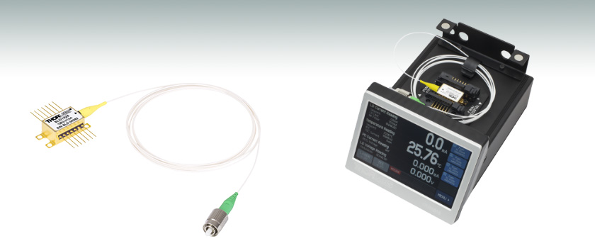
- Broadband Emission Wavelengths from 770 nm to 1610 nm
- Low Ripple
- Butterfly Package
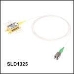
SLD1325
1325 nm SLD, >100 nm Bandwidth
30 dB (Min) Optical Isolation
Application Idea
SLD1550S-A2
Superluminescent Diode
Mounted in a CLD1015 Compact
Laser Diode Driver with TEC

Please Wait
| Recommended Controller / Mount Options | |||
|---|---|---|---|
| Item # | Mount | Diode Driver | TEC Controller |
| CLD1015 | |||
| LM14S2 | - | - | |
| ITC4000 Series | Use with LM14S2 Mount | ||
| LDC200 Series | Use with LM14S2 Mount | - | |
| TED200C | Use with LM14S2 Mount | - | |
特長
- 中心波長770 nm~1610 nm
- 3 dBバンド幅(典型値):18~110 nm
- 中心波長が1220 nm、1315 nm、1325 nm、1400 nmのスーパールミネッセントダイオード(SLD)は、光アイソレータ内蔵の製品を標準品としてご用意しております。
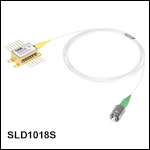
- 14ピンバタフライパッケージ、長さ≥ 1 mのSMまたはPMファイバピグテール付き
- 2.0 mmナローキー付きFC/APCコネクタ
- TECおよびサーミスタ内蔵
スーパールミネッセントダイオード(SLD)は高出力で広帯域な優れた光源であり、光コヒーレンストモグラフィ(OCT)イメージングシステムや光ファイバージャイロスコープ(FOG)などの用途に適しています。
近赤外域(NIR)用スーパールミネッセントダイオードは中心波長770 nm~1610 nmでご用意しています(右表からクリックしてご覧ください)。こちらのバタフライパッケージのSLDのうち、波長1100 nmまでの製品はガリウムヒ素(GaAs)を基板としており、その他はインジウムリン(InP)を基板にしています。
各デバイスの14ピンバタフライパッケージにはペルチェ素子およびサーミスタが内蔵されているため、安定した出力を得ることができます。出力光はシングルモードファイバまたは偏波保持ファイバに結合されており、それらのファイバには2.0 mmのナローキーFC/APCコネクタが接続されています。なお、戻り光があると、出力光パワーが減少したり、あるいはSLDが損傷したりするすることがありますのでご注意ください。当社では、こちらのSLDに対して、FC/PCコネクタのような後方反射しやすいコンポーネントを使用することは推奨していません。スーパールミネッセントダイオードSLD1220x、SLD1310x、SLD1325、SLD1330x、SLD1410xにはアイソレータが内蔵されています。波長の異なるSLDで光アイソレータの内蔵された製品をご希望の場合は、当社までお問い合わせください。
仕様は上の「仕様」タブからご覧いただけます。各SLDは、スペクトルおよび動作パラメータに関する情報を含む製品固有のデータシートとともに発送致します。各SLDの試験データをご希望の場合は、当社までお問い合わせください。
スペクトルの比較グラフは上の「スペクトルの比較」タブでご覧いただけます。こちらのページでご紹介しているSLD光源のスペクトル形状には、ガウシアンに近いものと上部が平坦なものがございます。それらの2つの異なるスペクトル形状により、中心波長の求め方が異なります。計算方法については「仕様」タブをご覧ください。
ご希望の波長において低いリップルのSLDや、より高い出力のSLDをカスタムでご提供することも可能です。但し、費用にはカスタム設計費やウエハ製造のコストも含まれるため、少ロットでのご要望の場合は、割高となることをご承知おきください。SLDのお見積りは、お気軽に当社までお問い合わせください。こちらでご紹介しているSLDは、ベンチトップ型でご提供している製品もございます。詳細は「セレクションガイド」のタブをご参照ください。
超広帯域なスーパールミネッセントダイオードを製造するという性質上、下記のSLD光源の何種類かはガウシアンに近いスペクトルを有しますが、その他は上部が平坦なスペクトルになります。このように異なるスペクトル形状が存在するため、ダイオードの特性を的確に表現するためには、中心波長を2つの異なる方法で定義する必要があります。
ガウシアンに近い場合の中心波長の定義
スペクトル形状がガウシアンに近いデバイスの中心波長は相対振幅の加重平均によって定義しています。スペクトルの形状にばらつきがあることから、この値はピークパワーの波長やFWHMに基づく中心波長には一致しない場合があります。光スペクトラムアナライザ(OSA)のトレースデータから、中心波長は以下の式で求められます。

ここで、
- CWは仕様として示される中心波長
- Xi はトレースデータポイントの波長
- Yi はトレースデータポイントの振幅
上部が平坦な場合の中心波長の定義
上部が平坦のスペクトル形状を持つデバイスの中心波長は、スペクトルのピークから3 dB下がった位置にある2つの波長の中間点と定義します。OSAのトレースデータから、中心波長は以下の式で求められます。

ここで、
- CWは仕様として示される中心波長
- XR_3dB は3 dB帯域幅の右端の波長
- XL_3dB は3 dB帯域幅の左端の波長
SLDの仕様
下記の仕様はガイドラインとして示しています。各SLDに添付される特性評価シートには、そのデバイス固有の動作パラメータに対する最小値、最大値、推奨値、および仕様が記載されています。ASEパワーの仕様はファイバーピグテールからの出力値を示しています。
770 nmスーパールミネッセントダイオード
| Item # | SLD770S | ||
|---|---|---|---|
| Parametera | Min | Typ. | Max |
| Operating Current | - | - | 170 mA |
| Center Wavelength (CWL)b | 760 nm | 770 nm | 780 nm |
| Spectral Shape | Near Gaussian | ||
| ASE Powerc | 4.5 mW | 5.5 mW | - |
| Optical 3 dB Bandwidthc,d | 15 nm | 18 nm | - |
| RMS Gain Ripplec | - | 0.01 dB | 0.3 dB |
| Forward Voltagec | - | 1.95 V | 2.5 V |
| Fiber Type | 780HP (SM) | ||
| TEC Operation: Typ. / Max @ TCASE = 25 °C / 70 °C | |||
| TEC Current | - | 0.11 A | 1.4 A |
| TEC Voltage | - | 0.16 V | 4.0 V |
| Thermistor Resistance | - | 10 kΩ | - |
| Performance Graphs (Click Icons for Plots) | |||
| Output Spectrum | |||
| LIV Plot | |||
| Gain Ripplec,e | |||
| Absolute Maximum Ratingsa | |||
| Absolute Max Current | 170 mA | ||
| Operating Case Temperature | 0 to 70 °C | ||
| Storage Temperature | -10 to 70 °C | ||
| Pin Code | 14 Pin, Type 1 | ||
810 nmスーパールミネッセントダイオード
| Item # | SLD810S | |||||
|---|---|---|---|---|---|---|
| Parametera | Min | Typical | Max | |||
| Operating Current | - | - | 270 mA | |||
| Center Wavelength (CWL)b | 795 nm | 810 nm | 825 nm | |||
| Spectral Shape | Near Gaussian | |||||
| ASE Powerc | 13 mW | 15 mW | - | |||
| Optical 3 dB Bandwidthc,d | 25 nm | 30 nm | - | |||
| RMS Gain Ripplec | - | 0.03 dB | 0.15 dB | |||
| Forward Voltage | - | 2.1 V | 2.5 V | |||
| Fiber | 780HP (SM) | |||||
| TEC Operation: Typ. / Max @ TCASE = 25 °C / 70 °C | ||||||
| TEC Current | - | 0.2 A | 1.4 A | |||
| TEC Voltage | - | 0.3 V | 6.0 V | |||
| Thermistor Resistance | - | 10 kΩ | - | |||
| Performance Graphs (Click Icons for Plots) | ||||||
| Output Spectrum | ||||||
| LIV Plot | ||||||
| Gain Ripplec,e | ||||||
| Absolute Maximum Ratingsa | ||||||
| Absolute Max Current | 290 mA | |||||
| Operating Case Temperature | 0 to 70 °C | |||||
| Storage Temperature | -10 to 70 °C | |||||
| Pin Code | 14 Pin, Type 1 | |||||
830 nmスーパールミネッセントダイオード
| Item # | SLD830S-A10W | SLD830S-A20W | SLD830S-A10 | SLD830S-A20 | ||||||||
|---|---|---|---|---|---|---|---|---|---|---|---|---|
| Parametera | Min | Typical | Max | Min | Typical | Max | Min | Typical | Max | Min | Typical | Max |
| Operating Current | - | - | 240 mA | - | - | 330 mA | - | - | 150 mA | - | - | 240 mA |
| Center Wavelength (CWL)b | 815 nm | 830 nm | 845 nm | 815 nm | 830 nm | 845 nm | 820 nm | 830 nm | 840 nm | 820 nm | 830 nm | 840 nm |
| Spectral Shape | Flat Top | Flat Top | Near Gaussian | Near Gaussian | ||||||||
| ASE Powerc,d | 10 mW | - | - | 20 mW | - | - | 10 mW | 13 mW | - | 20 mW | 22 mW | - |
| Optical 3 dB Bandwidthc,e | 50 nm | 60 nm | - | 40 nm | 55 nm | - | 17 nm | 20 nm | - | 17 nm | 20 nm | - |
| Optical 20 dB Bandwidthc | - | - | - | - | - | - | - | 50 nm | - | - | 50 nm | - |
| RMS Gain Ripplec,f | - | 0.06 dB | 0.3 dB | - | 0.03 dB | 0.3 dB | - | 0.03 dB | 0.15 dB | - | 0.03 dB | 0.15 dB |
| Forward Voltage | - | 2.0 V | 2.5 V | - | 2.0 V | 2.5 V | - | 2.0 V | 2.5 V | - | 2.0 V | 2.5 V |
| Fiber Type | 780HP | 780HP | 780HP | 780HP | ||||||||
| TEC Operation: Typ. / Max @ TCASE = 25 °C / 70 °C | ||||||||||||
| TEC Current | - | 0.14 A | 1.4 A | - | 0.14 A | 1.4 A | - | 0.1 A | 1.5 A | - | 0.1 A | 1.5 A |
| TEC Voltage | - | 0.18 V | 6.0 V | - | 0.18 V | 6.0 V | - | 0.13 V | 4.0 V | - | 0.13 V | 4.0 V |
| Thermistor Resistance | - | 10 kΩ | - | - | 10 kΩ | - | - | 10 kΩ | - | - | 10 kΩ | - |
| Performance Graphs (Click Icons for Plots) | ||||||||||||
| Output Spectrum | ||||||||||||
| LIV Plot | ||||||||||||
| Gain Ripplef | ||||||||||||
| Absolute Maximum Ratingsa | ||||||||||||
| Absolute Max Current | 240 mA | 330 mA | 150 mA | 240 mA | ||||||||
| Operating Case Temperature | 0 to 70 °C | 0 to 70 °C | 0 to 70 °C | 0 to 70 °C | ||||||||
| Storage Temperature | -10 to 70 °C | -10 to 70 °C | -10 to 70 °C | -10 to 70 °C | ||||||||
| Pin Code | 14 Pin, Type 1 | 14 Pin, Type 1 | 14 Pin, Type 1 | 14 Pin, Type 1 | ||||||||
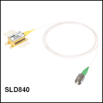
840 nmスーパールミネッセントダイオード
| Item # | SLD840x | |||||
|---|---|---|---|---|---|---|
| Parametera | Min | Typical | Max | |||
| Operating Current | - | 140 mA | 180 mA | |||
| Center Wavelength (CWL)b | 820 nm | 840 nm | 860 nm | |||
| Spectral Shape | Flat Top | |||||
| ASE Powerc,d | 3 mW | 4 mW | - | |||
| Optical 3 dB Bandwidthc,e | 60 nm | 70 nm | - | |||
| RMS Gain Ripplec,f | - | 0.01 dB | 0.1 dB | |||
| Forward Voltage | - | 2.0 V | 2.5 V | |||
| Fiber | 780HP (SM) PM780-HP (PM)g | |||||
| TEC Operation: Typ. / Max @ TCASE = 25 °C / 70 °C | ||||||
| TEC Current | - | 0.1 A | 1.5 A | |||
| TEC Voltage | - | 0.15 V | 4.0 V | |||
| Thermistor Resistance | - | 10 kΩ | - | |||
| Performance Graphs (Click Icons for Plots) | ||||||
| Output Spectrum |
| |||||
| LIV Plot |
| |||||
| Gain Ripplef |
| |||||
| Absolute Maximum Ratingsa | ||||||
| Absolute Max Current | 180 mA | |||||
| Operating Case Temperature | 0 °C to 70 °C | |||||
| Storage Temperature | -10 °C to 70 °C | |||||
| Pin Code | 14 Pin, Type 1 | |||||
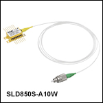
850 nmスーパールミネッセントダイオード
| Item # | SLD850S-A10W | SLD850S-A20W | ||||
|---|---|---|---|---|---|---|
| Parametera | Min | Typical | Max | Min | Typical | Max |
| Operating Current | - | - | 180 mA | - | - | 340 mA |
| Center Wavelength (CWL)b | 835 nm | 850 nm | 865 nm | 835 nm | 850 nm | 865 nm |
| Spectral Shape | Flat Top | Flat Top | ||||
| ASE Powerc,d | 10 mW | - | - | 20 mW | - | - |
| Optical 3 dB Bandwidthc,e | 40 nm | 60 nm | - | 40 nm | 55 nm | - |
| RMS Gain Ripplec,f | - | 0.03 dB | 0.3 dB | - | 0.03 dB | 0.3 dB |
| Forward Voltage | - | 2.0 V | 2.5 V | - | 2.0 V | 2.5 V |
| Fiber Type | 780HP | 780HP | ||||
| TEC Operation: Typ. / Max @ TCASE = 25 °C / 70 °C | ||||||
| TEC Current | - | 0.11 A | 1.4 A | - | 0.18 A | 1.4 A |
| TEC Voltage | - | 0.17 V | 6.0 V | - | 0.27 V | 6.0 V |
| Thermistor Resistance | - | 10 kΩ | - | - | 10 kΩ | - |
| Performance Graphs (Click Icons for Plots) | ||||||
| Output Spectrum | ||||||
| LIV Plot | ||||||
| Gain Ripplef | ||||||
| Absolute Maximum Ratingsa | ||||||
| Absolute Max Current | 180 mA | 340 mA | ||||
| Operating Case Temperature | 0 to 70 °C | 0 to 70 °C | ||||
| Storage Temperature | -10 to 70 °C | -10 to 70 °C | ||||
| Pin Code | 14 Pin, Type 1 | 14 Pin, Type 1 | ||||
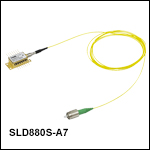
880 nmスーパールミネッセントダイオード
| Item # | SLD880S-A7 | SLD880S-A25 | ||||
|---|---|---|---|---|---|---|
| Parametera | Min | Typical | Max | Min | Typical | Max |
| Operating Current | - | - | 225 mA | - | - | 410 mA |
| Center Wavelength (CWL)b | 860 nm | 880 nm | 900 nm | 860 nm | 880 nm | 900 nm |
| Spectral Shape | Flat Top | Flat Top | ||||
| ASE Powerc,d | 6 mW | 7 mW | - | 23 mW | 25 mW | - |
| Optical 3 dB Bandwidthc | 35 nm | 40 nm | - | 35 nm | 40 nm | - |
| Optical 20 dB Bandwidthc | - | 80 nm | - | - | 80 nm | - |
| RMS Gain Ripplec,e | - | 0.06 dB | 0.3 dB | - | 0.06 dB | 0.3 dB |
| Forward Voltagec | - | 2.0 V | 2.5 V | - | 2.0 V | 2.5 V |
| Fiber Type | 780HP | 780HP | ||||
| TEC Operation: Typ. / Max @ TCASE = 25 °C / 70 °C | ||||||
| TEC Current | - | 0.2 A | 1.4 A | - | 0.2 A | 1.4 A |
| TEC Voltage | - | 0.8 V | 6.0 V | - | 0.8 V | 6.0 V |
| Thermistor Resistance | - | 10 kΩ | - | - | 10 kΩ | - |
| Performance Graphs (Click Icons for Plots) | ||||||
| Output Spectrum | ||||||
| LIV Plot | ||||||
| Gain Ripplee | ||||||
| Absolute Maximum Ratingsa | ||||||
| Absolute Max Current | 225 mA | 410 mA | ||||
| Operating Case Temperature | 0 to 70 °C | 0 to 70 °C | ||||
| Storage Temperature | -10 to 70 °C | -10 to 70 °C | ||||
| Pin Code | 14 Pin, Type 1 | 14 Pin, Type 1 | ||||
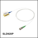
920 nmスーパールミネッセントダイオード
| Item # | SLD920x | |||||
|---|---|---|---|---|---|---|
| Parametera | Min | Typical | Max | |||
| Operating Current | - | - | 420 mA | |||
| Center Wavelength (CWL)b | 895 nm | 920 nm | 945 nm | |||
| Spectral Shape | Flat Top | |||||
| ASE Powerc,d | 10 mW | 15 mW | - | |||
| Optical 3 dB Bandwidthc,e | 50 nm | 65 nm | - | |||
| RMS Gain Ripplec,f | - | 0.02 dB | 0.3 dB | |||
| Forward Voltage | - | 2.0 V | 2.5 V | |||
| Fiber | 780HP (SM) PM780-HP (PM)g | |||||
| TEC Operation: Typ. / Max @ TCASE = 25 °C / 70 °C | ||||||
| TEC Current | - | 0.3 A | 1.4 A | |||
| TEC Voltage | - | 0.4 V | 6.0 V | |||
| Thermistor Resistance | - | 10 kΩ | - | |||
| Performance Graphs (Click Icons for Plots) | ||||||
| Output Spectrum | ||||||
| LIV Plot | ||||||
| Gain Ripplee | ||||||
| Absolute Maximum Ratingsa | ||||||
| Absolute Max Current | 420 mA | |||||
| Operating Case Temperature | 0 °C to 70 °C | |||||
| Storage Temperature | -10 °C to 70 °C | |||||
| Pin Code | 14 Pin, Type 1 | |||||
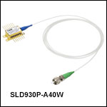
930 nmスーパールミネッセントダイオード
| Item # | SLD930x-A40W | |||||
|---|---|---|---|---|---|---|
| Parametera | Min | Typical | Max | |||
| Operating Current | - | - | 800 mA | |||
| Center Wavelength (CWL)b | 915 nm | 930 nm | 945 nm | |||
| Spectral Shape | Flat Top | |||||
| ASE Powerc,d | 36 mW | 40 mW | - | |||
| Optical 3 dB Bandwidthc,e | 40 nm | 45 nm | - | |||
| RMS Gain Ripplec,f | - | 0.06 dB | 0.3 dB | |||
| Forward Voltage | - | 2.0 V | 2.5 V | |||
| Fiber | 780HP (SM) PM780-HP (PM)g | |||||
| TEC Operation: Typ. / Max @ TCASE = 25 °C / 70 °C | ||||||
| TEC Current | - | 0.54 A | 1.4 A | |||
| TEC Voltage | - | 0.78 V | 6.0 V | |||
| Thermistor Resistance | - | 10 kΩ | - | |||
| Performance Graphs (Click Icons for Plots) | ||||||
| Output Spectrum |
| |||||
| LIV Plot |
| |||||
| Gain Ripplef |
| |||||
| Absolute Maximum Ratingsa | ||||||
| Absolute Max Current | 800 mA | |||||
| Operating Case Temperature | 0 °C to 70 °C | |||||
| Storage Temperature | -10 °C to 70 °C | |||||
| Pin Code | 14 Pin, Type 1 | |||||
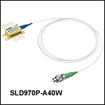
970 nmスーパールミネッセントダイオード
| Item # | SLD970x-A40W | ||
|---|---|---|---|
| Parametera | Min | Typical | Max |
| Operating Current | - | 1000 mA | 1010 mA |
| Center Wavelength (CWL)b | 945 nm | 970 nm | 995 nm |
| Spectral Shape | Flat Top | ||
| ASE Powerc,d | 35 mW | 40 mW | - |
| Optical 3 dB Bandwidthc,e | 40 nm | 50 nm | - |
| RMS Gain Ripplec,f | - | 0.03 dB | 0.2 dB |
| Forward Voltage | - | 1.2 V | 2.5 V |
| Fiber Type | HI1060 (SM) PM980-XP (PM)g | ||
| TEC Operation: Typ. / Max @ TCASE = 25 °C / 70 °C | |||
| TEC Current | - | 0.83 A | 1.4 A |
| TEC Voltage | - | 0.12 V | 6.0 V |
| Thermistor Resistance | - | 10 kΩ | - |
| Performance Graphs (Click Icons for Plots) | |||
| Output Spectrum | |||
| LIV Plot | |||
| Gain Ripplef | |||
| Absolute Maximum Ratingsa | |||
| Absolute Max Current | 1010 mA | ||
| Operating Case Temperature | 0 °C to 70 °C | ||
| Storage Temperature | -10 °C to 70 °C | ||
| Pin Code | 14 Pin, Type 1 | ||
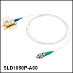
1050 nmスーパールミネッセントダイオード
| Item # | SLD1050x | SLD1050S-A60 | SLD1050P-A60 | |||||||||
|---|---|---|---|---|---|---|---|---|---|---|---|---|
| Parametera | Min | Typical | Max | Min | Typical | Max | Min | Typical | Max | |||
| Operating Current | - | - | 300 mA | - | - | 1010 mA | - | - | 1010 mA | |||
| Center Wavelength (CWL)b | 1030 nm | 1050 nm | 1070 nm | 1025 nm | 1050 nm | 1075 nm | 1025 nm | 1050 nm | 1075 nm | |||
| Spectral Shape | Near Gaussian | Flat Top | Flat Top | |||||||||
| ASE Powerc,d | 6 mW | 8 mW | - | 55 mW | 60 mW | - | 55 mW | 60 mW | - | |||
| Optical 3 dB Bandwidthc,e | 40 nm | 50 nm | - | 60 nm | 70 nm | - | 60 nm | 70 nm | - | |||
| Optical 20 dB Bandwidthc | - | - | - | - | 100 nm | - | - | - | - | |||
| RMS Gain Ripplec,f | - | 0.1 dB | 0.25 dB | - | 0.03 dB | 0.2 dB | - | 0.06 dB | 0.3 dB | |||
| Forward Voltagec | - | 2.0 V | 2.5 V | - | 2.0 V | 2.5 V | - | 1.9 V | 2.5 V | |||
| Fiber Type | HI1060 (SM) PM980-XP (PM)g | HI1060 | PM980-XPg | |||||||||
| TEC Operation: Typ. / Max @ TCASE = 25 °C / 70 °C | ||||||||||||
| TEC Current | - | 0.25 A | 1.5 A | - | 0.7 A | 2.5 A | - | 0.7 A | 2.5 A | |||
| TEC Voltage | - | 0.30 V | 4.0 V | - | 0.9 V | 3.2 V | - | 1.0 V | 3.2 V | |||
| Thermistor Resistance | - | 10 kΩ | - | - | 10 kΩ | - | - | 10 kΩ | - | |||
| Performance Graphs (Click Icons for Plots) | ||||||||||||
| Output Spectrum |
| |||||||||||
| LIV Plot |
| |||||||||||
| Gain Ripplef | - | |||||||||||
| Absolute Maximum Ratingsa | ||||||||||||
| Absolute Max Current | 360 mA | 1010 mA | 1010 mA | |||||||||
| Operating Case Temperature | 0 °C to 70 °C | 0 °C to 70 °C | 0 °C to 70 °C | |||||||||
| Storage Temperature | - | -10 °C to 70 °C | -10 °C to 70 °C | |||||||||
| Chip Temperature (TEC) | 10 °C to 30 °C | - | - | |||||||||
| Pin Code | 14 Pin, Type 1 | 14 Pin, Type 1 | 14 Pin, Type 1 | |||||||||
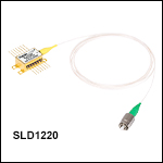
1220 nmスーパールミネッセントダイオード
| Item # | SLD1220x | |||||||||||
|---|---|---|---|---|---|---|---|---|---|---|---|---|
| Parametera | Min | Typ. | Max | |||||||||
| Center Wavelength (CWL)b | 1205 nm | 1220 nm | 1235 nm | |||||||||
| Spectral Shape | Flat Top | |||||||||||
| Operating Current | - | 400 mA | 450 mA | |||||||||
| ASE Powerc,d | 4 mW | 5 mW | - | |||||||||
| Optical 3 dB Bandwidthc,e | 85 nm | 90 nm | - | |||||||||
| RMS Gain Ripplec,f | - | 0.05 dB | 0.35 dB | |||||||||
| Forward Voltagec | - | 1.7 V | 2.0 V | |||||||||
| TEC Operation: Typ. / Max @ TCASE = 25 °C / 70 °C | ||||||||||||
| TEC Current | - | 0.28 A | 1.5 A | |||||||||
| TEC Voltage | - | 0.39 V | 3.5 V | |||||||||
| Thermistor Resistance | - | 10 kΩ | - | |||||||||
| Integrated Isolator | ||||||||||||
| Isolation | - | 50 dB | - | |||||||||
| Performance Graphs (Click Icons for Plots) | ||||||||||||
| Output Spectrum |
| |||||||||||
| LIV Plot |
| |||||||||||
| Absolute Maximum Ratingsg | ||||||||||||
| Absolute Max Current | 1.5 A | |||||||||||
| Operating Case Temperature | 0 to 70 °C | |||||||||||
| Storage Temperature | -10 to 70 °C | |||||||||||
| Pin Code | 14 Pin, Type 1 | |||||||||||
| Fiber Specifications | ||||||||||||
| Fiber Type | HI1060 (SM) Corning® PM13-U40A (PM) | |||||||||||
| Numerical Aperture | 0.14 (SM) 0.12 (PM) | |||||||||||
| Mode Field Diameter (Nominal) | 5.9 ± 0.3 µm @ 980 nm (SM) 6.2 ± 0.3 µm @ 1030 nm (SM) 9.3 ± 0.5 µm @ 1550 nm (PM) | |||||||||||
| Fiber Length | 1.50 ± 0.05 m | |||||||||||
| Connector | FC/APC, 2.0 mm Narrow Keyh | |||||||||||
1310 nmおよび1315 nmスーパールミネッセントダイオード
| Item # | SLD1021S | SLD1018x | SLD1310 | SLD1310P | ||||||||
|---|---|---|---|---|---|---|---|---|---|---|---|---|
| Parametera | Min | Typical | Max | Min | Typical | Max | Min | Typical | Max | Min | Typical | Max |
| Operating Current | - | 700 mA | 900 mA | - | 600 mA | 800 mA | - | 900 mA | 1000 mA | - | 900 mA | 1000 mA |
| Center Wavelength (CWL)b | 1290 nm | - | 1330 nm | 1290 nm | - | 1330 nm | 1300 nm | 1315 nm | 1330 nm | 1300 nm | 1315 nm | 1330 nm |
| Spectral Shape | Near Gaussian | Near Gaussian | Flat Top | Flat Top | ||||||||
| ASE Powerc,d | 10 mW | 12.5 mW | - | 22 mW | 30 mW | - | 22 mW | 30 mW | - | 22 mW | 30 mW | - |
| Optical 3 dB Bandwidthc,d,e | 80 nm | 85 nm | - | 40 nm | 45 nm | - | 75 nm | 90 nm | - | 75 nm | 90 nm | - |
| RMS Gain Ripplec,f | - | - | 0.35 dB | - | 0.1 dB | 0.35 dB | - | 0.12 dB | 0.3 dB | - | 0.12 dB | 0.35 dB |
| Forward Voltagec | - | 1.55 V | 2.0 V | - | 1.5 V | 1.8 V | - | 2.0 V | 2.3 V | - | 1.5 V | 1.8 V |
| Polarization Extinction Ratio (PER) | - | - | - | - | - | - | - | - | - | - | 23 dB | - |
| Fiber Type | SMF-28e+ | SMF-28e+ (SM) Corning PM 13-U40A (PM)g | SMF-28e | Corning PM13-U40Ag | ||||||||
| TEC Operationh | ||||||||||||
| TEC Current | - | 0.4 A | 1.5 A | - | 0.4 A | 1.5 A | - | 0.7 A | 1.5 A | - | 0.7 A | 1.5 A |
| TEC Voltage | - | 0.5 V | 4 V | - | 0.5 V | 4 V | - | 1.0 V | 4.0 V | - | 1.0 V | 4.0 V |
| Thermistor Resistance | - | 10 kΩ | - | - | 10 kΩ | - | - | 10 kΩ | - | - | 10 kΩ | - |
| Integrated Isolator | ||||||||||||
| Isolation | N/Ai | N/Ai | - | 50 dB | - | - | 50 dB | - | ||||
| Performance Plots (Click Icons for Plots) | ||||||||||||
| Output Spectrum | ||||||||||||
| LIV Plot | ||||||||||||
| Gain Ripplef | - | - | ||||||||||
| Absolute Maximum Ratingsj | ||||||||||||
| Absolute Max Current | - | - | 1000 mA | 1000 mA | ||||||||
| Operating Case Temperature | - | - | 0 °C to 70 °C | 0 °C to 70 °C | ||||||||
| Storage Temperature | - | - | -10 °C to 70 °C | -10 °C to 70 °C | ||||||||
| Pin Code | 14 Pin, Type 1 | 14 Pin, Type 1 | 14 Pin, Type 1 | 14 Pin, Type 1 | ||||||||
1325 nmスーパールミネッセントダイオード
1400 nmスーパールミネッセントダイオード
1450 nmスーパールミネッセントダイオード
| Item # | SLD1450x | |||||
|---|---|---|---|---|---|---|
| Parametera | Min | Typical | Max | |||
| Operating Current | - | 500 mA | 600 mA | |||
| Center Wavelength (CWL)b | 1435 nm | 1450 nm | 1465 nm | |||
| Spectral Shape | Near Gaussian | |||||
| ASE Powerc,d | 23 mW | 25 mW | - | |||
| Optical 3 dB Bandwidthc,e | 50 nm | 54 nm | - | |||
| RMS Gain Ripplec,f | - | 0.06 dB | 0.35 dB | |||
| Forward Voltage | - | 1.7 V | 2.0 V | |||
| Fiber | SMF-28e (SM) Corning® PM15-U40A (PM)g | |||||
| TEC Operation: Typ. / Max @ TCASE = 25 °C / 70 °C | ||||||
| TEC Current | - | 0.3 A | 1.5 A | |||
| TEC Voltage | - | 0.4 V | 4.0 V | |||
| Thermistor Resistance | - | 10 kΩ | - | |||
| Performance Graphs (Click Icons for Plots) | ||||||
| Output Spectrum |
| |||||
| LIV Plot |
| |||||
| Gain Ripplef |
| |||||
| Absolute Maximum Ratingsa | ||||||
| Absolute Max Current | 600 mA | |||||
| Operating Case Temperature | 0 °C to 70 °C | |||||
| Storage Temperature | -10 °C to 70 °C | |||||
| Pin Code | 14 Pin, Type 1 | |||||
1550 nmスーパールミネッセントダイオード
| Item # | SLD1550x-A1 | SLD1550x-A2 | SLD1005S | SLD1550x-A40 | ||||||||
|---|---|---|---|---|---|---|---|---|---|---|---|---|
| Parametera | Min | Typical | Max | Min | Typical | Max | Min | Typical | Max | Min | Typical | Max |
| Operating Current | - | 450 mA | 600 mA | - | 550 mA | 600 mA | - | 600 mA | 800 mA | - | 750 mA | 900 mA |
| Center Wavelength (CWL)b | 1520 nm | 1550 nm | 1580 nm | 1520 nm | 1550 nm | 1580 nm | 1530 nm | 1550 nm | 1570 nm | 1530 nm | 1550 nm | 1570 nm |
| Spectral Shape | Near Gaussian | Near Gaussian | Near Gaussian | Near Gaussian | ||||||||
| ASE Powerc,d | 0.75 mW | 1.0 mW | - | 2.0 mW | 2.5 mW | - | 20 mW | 22 mW | - | 35 mW | 40 mW | - |
| Optical 3 dB Bandwidthc | 90 nm | 110 nm | - | 85 nm | 90 nm | - | 45 nm | 50 nm | - | 30 nm | 33 nm | - |
| RMS Gain Ripplec,e | - | - | 0.1 dB | - | - | 0.25 dB | - | 0.2 dB | 0.35 dB | - | 0.2 dB | 0.35 dB |
| Forward Voltagec | - | 1.6 V | 2.0 V | - | 1.6 V | 2.0 V | - | 1.4 V | 1.8 V | - | 1.4 V | 1.8 V |
| Fiber Type | SMF-28e+ (SM) Corning PM 15-U40A (PM)f | SMF-28e+ (SM) Corning PM 15-U40A (PM)f | SMF-28e+ | SMF-28e+ (SM) Corning PM 15-U40A (PM)f | ||||||||
| TEC Operation: Typ. / Max @ TCASE = 25 °C / 65 °C | ||||||||||||
| TEC Current | - | 0.35 A | 1.5 A | - | 0.35 A | 1.5 A | - | 0.3 A | 1.5 A | - | 0.3 A | 1.5 A |
| TEC Voltage | - | 0.5 V | 3.5 V | - | 0.5 V | 3.5 V | - | 0.3 V | 3.5 V | - | 0.3 V | 3.5 V |
| Thermistor Resistance | - | 10 kΩ | - | - | 10 kΩ | - | - | 10 kΩ | - | - | 10 kΩ | - |
| Performance Plots (Click Icon for Plot) | ||||||||||||
| Output Spectrum | ||||||||||||
| LIV Plot | ||||||||||||
1610 nmスーパールミネッセントダイオード
| Item # | SLD1610x | |||||
|---|---|---|---|---|---|---|
| Parametera | Min | Typical | Max | |||
| Operating Current | - | 800 mA | 900 mA | |||
| Center Wavelength (CWL)b | 1590 nm | 1610 nm | 1630 nm | |||
| Spectral Shape | Near Gaussian | |||||
| ASE Powerc,d | 22 mW | 27 mW | - | |||
| Optical 3 dB Bandwidthc,e | 50 nm | 57 nm | - | |||
| RMS Gain Ripplec,f | - | 0.2 dB | 0.5 dB | |||
| Forward Voltage | - | 1.8 V | 2.2 V | |||
| Fiber | SMF-28e (SM) Corning® PM15-U40A (PM)g | |||||
| TEC Operation: Typ. / Max @ TCASE = 25 °C / 70 °C | ||||||
| TEC Current | - | 0.5 A | 1.5 A | |||
| TEC Voltage | - | 0.8 V | 4.0 V | |||
| Thermistor Resistance | - | 10 kΩ | - | |||
| Performance Graphs (Click Icons for Plots) | ||||||
| Output Spectrum |
| |||||
| LIV Plot |
| |||||
| Gain Ripplef |
| |||||
| Absolute Maximum Ratingsa | ||||||
| Absolute Max Current | 900 mA | |||||
| Operating Case Temperature | 0 °C to 70 °C | |||||
| Storage Temperature | -10 °C to 70 °C | |||||
| Pin Code | 14 Pin, Type 1 | |||||
近赤外域(NIR)用スーパールミネッセントダイオード(SLD)の発光スペクトルの比較
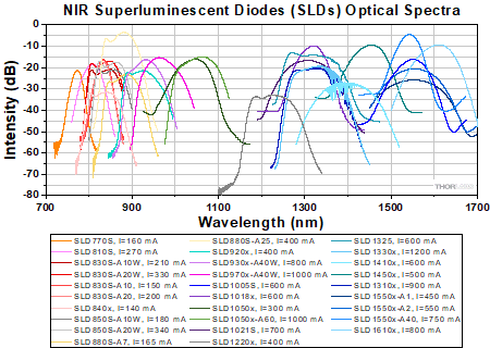
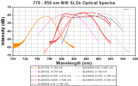
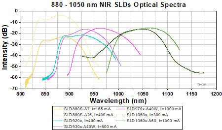
ここでは、当社のすべての近赤外域用スーパールミネッセントダイオードの発光スペクトルを比較したグラフと、波長域ごとにそれらの詳細を示したグラフをご覧いただけます。下のグラフで、シングルモードファイバ結合型と偏波保持ファイバ結合型の両方のタイプがあるSLDのスペクトルは、1つのスペクトルで表されています。そのスペクトルデータは両方のタイプに適用され、またSLDの型番には「x」が記載されています。すべての発光スペクトルの生データはこちらからダウンロードできます。
Click to Enlarge
すべてのNIR SLDの発光スペクトルの比較
Click to Enlarge
中心波長770~850 nmのNIR SLDの発光スペクトルの比較
Click to Enlarge
中心波長880~1050 nmのNIR SLDの発光スペクトルの比較

Click to Enlarge
中心波長1220~1610 nmのNIR SLDの発光スペクトルの比較
バタフライ型パッケージ、タイプ1
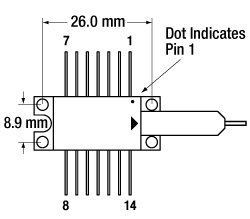
| Pin | Description | Pin | Description |
|---|---|---|---|
| 1 | + TEC | 14 | - TEC |
| 2 | Thermistor | 13 | Case Ground |
| 3 | Not Connected | 12 | Not Connected |
| 4 | Not Connected | 11 | SLD Cathode |
| 5 | Thermistor | 10 | SLD Anode |
| 6 | Not Connected | 9 | Not Connected |
| 7 | Not Connected | 8 | Not Connected |
スーパールミネッセントダイオードの性能
緑色の欄はOCTシステムに適した製品です。
| Item # | Center Wavelength | Package | Output Powera | Bandwidth (3 dB) | Optical Spectrum | LIV Curvesb | Integrated Isolator | Equivalent Benchtop Source |
|---|---|---|---|---|---|---|---|---|
| SLD405B | 405 nm | Butterfly, SM Pigtail | 5 mW | 3 nm | No | No | ||
| SLD450B | 450 nm | Butterfly, SM Pigtail | 5 mW | 6 nm | No | No | ||
| SLD450T | 450 nm | TO-56 | 10 mW | 5 nm | No | No | ||
| SLD510B | 510 nm | Butterfly, SM Pigtail | 1.5 mW | 8 nm | No | No | ||
| SLD635B | 635 nm | Butterfly, SM Pigtail | 3 mW | 6 nm | No | No | ||
| SLD635T | 635 nm | TO-56 | 10 mW | 5 nm | No | No | ||
| SLD650B | 650 nm | Butterfly, SM Pigtail | 3 mW | 6 nm | No | No | ||
| SLD650T | 650 nm | TO-56 | 10 mW | 5 nm | No | No | ||
| SLD770S | 770 nmc | Butterfly, SM Pigtail | 5.5 mW | 18 nm | No | No | ||
| SLD810S | 810 nmc | Butterfly, SM Pigtail | 15 mW | 30 nm | No | No | ||
| SLD830S-A10W | 830 nmc | Butterfly, SM Pigtail | 10 mW (Min) | 60 nm | No | No | ||
| SLD830S-A20W | 830 nmc | Butterfly, SM Pigtail | 20 mW (Min) | 55 nm | No | No | ||
| SLD830S-A10 | 830 nmc | Butterfly, SM Pigtail | 13 mW | 20 nm | No | No | ||
| SLD830S-A20 | 830 nmc | Butterfly, SM Pigtail | 22 mW | 20 nm | No | No | ||
| SLD840 | 840 nmc | Butterfly, SM Pigtail | 4 mW | 70 nm | No | No | ||
| SLD840P | 840 nmc | Butterfly, PM Pigtail | 4 mW | 70 nm | No | No | ||
| SLD850S-A10W | 850 nmc | Butterfly, SM Pigtail | 10 mW (Min) | 60 nm | No | No | ||
| SLD850S-A20W | 850 nmc | Butterfly, SM Pigtail | 20 mW (Min) | 55 nm | No | No | ||
| SLD880S-A7 | 880 nmc | Butterfly, SM Pigtail | 7 mW | 40 nm | No | No | ||
| SLD880S-A25 | 880 nmc | Butterfly, SM Pigtail | 25 mW | 40 nm | No | No | ||
| SLD920S | 920 nmc | Butterfly, SM Pigtail | 15 mW | 65 nm | No | No | ||
| SLD920P | 920 nmc | Butterfly, PM Pigtail | 15 mW | 65 nm | No | No | ||
| SLD930S-A40W | 930 nmc | Butterfly, SM Pigtail | 40 mW | 45 nm | No | No | ||
| SLD930P-A40W | 930 nmc | Butterfly, PM Pigtail | 40 mW | 45 nm | No | No | ||
| SLD970S-A40W | 970 nmc | Butterfly, SM Pigtail | 40 mW | 50 nm | No | No | ||
| SLD970P-A40W | 970 nmc | Butterfly, PM Pigtail | 40 mW | 50 nm | No | No | ||
| SLD1050S | 1050 nmc | Butterfly, SM Pigtail | 8 mW | 50 nm | No | No | ||
| SLD1050P | 1050 nmc | Butterfly, PM Pigtail | 8 mW | 50 nm | No | No | ||
| SLD1050S-A60 | 1050 nmc | Butterfly, SM Pigtail | 60 mW | 70 nm | No | No | ||
| SLD1050P-A60 | 1050 nmc | Butterfly, PM Pigtail | 60 mW | 70 nm | No | No | ||
| SLD1021S | 1310 nmc | Butterfly, SM Pigtail | 12.5 mW | 85 nm | No | S5FC1021S | ||
| SLD1018S | 1310 nmc | Butterfly, SM Pigtail | 30 mW | 45 nm | No | S5FC1018S S5FC1018P | ||
| SLD1018P | 1310 nmc | Butterfly, PM Pigtail | 30 mW | 45 nm | No | S5FC1018S S5FC1018P | ||
| SLD1310 | 1315 nmc | Butterfly, SM Pigtail | 30 mW | 90 nm | Yes: 50 dB Isolation | No | ||
| SLD1310P | 1315 nmc | Butterfly, PM Pigtail | 30 mW | 90 nm | Yes: 50 dB Isolation | No | ||
| SLD1325 | 1325 nmc | Butterfly, SM Pigtail | 10 mW (Min) | 100 nm (Min) | Yes: 30 dB (Min) Isolation | No | ||
| SLD1330 | 1325 nmc | Butterfly, SM Pigtail | 40 mW | 90 nm | Yes: 50 dB Isolation | No | ||
| SLD1330P | 1325 nmc | Butterfly, SM Pigtail | 40 mW | 90 nm | Yes: 50 dB Isolation | No | ||
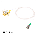
| SLD1410 | 1400 nmc | Butterfly, SM Pigtail | 5 mW | 98 nm | Yes: 30 dB Isolation | No | ||
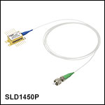
| SLD1450S | 1450 nmc | Butterfly, SM Pigtail | 25 mW | 54 nm | No | No | ||
| SLD1450P | 1450 nmc | Butterfly, PM Pigtail | 25 mW | 54 nm | No | No | ||
| SLD1550S-A1 | 1550 nmc | Butterfly, SM Pigtail | 1.0 mW | 110 nm | No | No | ||
| SLD1550P-A1 | 1550 nmc | Butterfly, PM Pigtail | 1.0 mW | 110 nm | No | No | ||
| SLD1550S-A2 | 1550 nmc | Butterfly, SM Pigtail | 2.5 mW | 90 nm | No | S5FC1550S-A2 S5FC1550P-A2 | ||
| SLD1550P-A2 | 1550 nmc | Butterfly, PM Pigtail | 2.5 mW | 90 nm | No | S5FC1550S-A2 S5FC1550P-A2 | ||
| SLD1005S | 1550 nmc | Butterfly, SM Pigtail | 22 mW | 50 nm | No | S5FC1005S | ||
| SLD1550S-A40 | 1550 nmc | Butterfly, SM Pigtail | 40 mW | 33 nm | No | No | ||
| SLD1550P-A40 | 1550 nmc | Butterfly, PM Pigtail | 40 mW | 33 nm | No | No | ||
| SLD1610 | 1610 nmc | Butterfly, SM Pigtail | 27 mW | 57 nm | No | No | ||
| SLD1610P | 1610 nmc | Butterfly, PM Pigtail | 27 mW | 57 nm | No | No |
| Posted Comments: | |
user
(posted 2024-03-12 06:47:40.687) Hi,
could you give any information about the polarization contrast (PER)? Specifically I'm interested in SLD810S. Thank you. cdolbashian
(posted 2024-03-15 04:31:55.0) Thank you for reaching out to us with this inquiry. While the SLD will be nominally polarized from the chip, we unfortunately do not characterize the polarization of these devices, as they are SM coupled, and the polarization will depend on the stress on the fiber as well as the ambient temperature the fiber experiences. For this reason, you can use a Paddle polarization controller to set your polarization state. I have contacted you directly to discuss this further. user
(posted 2024-01-18 22:13:26.72) is pin13, case connected to anode pin 10? jpolaris
(posted 2024-01-23 07:43:54.0) Thank you for contacting Thorlabs. Yes, for these NIR superluminescent diodes, case ground pin 13 and SLD anode pin 10 are connected. As in, they are not isolated with respect to one another in the circuit. jiao ren
(posted 2023-12-25 21:13:41.193) Can you provide the performance data (output spectrum, LIV plot, and gain ripple) of SLD830S-A20? Bob Holland
(posted 2023-08-10 10:01:15.507) I am just curious, why are products such as the 1050S-A60 not classified with a Laser Safety warning, when sold.
(as are all of the visible compact lasers of only a few mW)
A power of 60mW emitted from a SM fiber end would definitely be hazardous when viewed with an instrument.
Is this possibly because it is considered a "sub-component" and not a powered turn-key system?
Thanks in advance for your opinion here. jpolaris
(posted 2023-08-10 06:25:12.0) Thank you for contacting Thorlabs. You are exactly right. The output from sources such as SLD1050S-A60 will be dependent on the conditions under which they are driven. A turnkey system can be assigned a classification because there are defined bounds to the drive conditions, and thus also to the output from the source. user
(posted 2022-11-29 17:30:24.36) Is there a PCB design manual?
I'm not sure what to connect to pins 1, 2, 5, 10, 11, 13, and 14 ksosnowski
(posted 2022-11-29 09:54:13.0) Thanks for reaching out to Thorlabs. For each butterfly diode, e.g. SLD1005S, the performance data and spec sheet can be found on our product page, which includes the pinout for the diode. Our CLD1015 can serve as a laser mount, laser driver, and TEC driver. Our LM14S2 mount can also be used for connection if running the diode in Anode-Grounded configuration with a separate driver. I have reached out directly to discuss this further. Prashant Vadgaonkar
(posted 2022-07-12 02:29:30.273) Does the SLD830S-A10W emits the light with polarization within fiber?
Do we need "polarization scrambler" in the path? jgreschler
(posted 2022-07-15 09:31:43.0) Thank you for reaching out to Thorlabs. The SLD chip output is polarized, however the emission of the single mode fiber is going to depend on temperature and stress on the fiber. You can control these factors and the polarization state using a paddle controller to obtain your desired output polarization state. Prashant Vadgaonkar
(posted 2022-07-07 10:48:37.157) Hello! I try to use SLD830S-A10W with driver CLD1015.
We should check whether the Steinhart-Hart A,B and C of SLD is right. So, we want to know the SHH A,B and C values of SLD830S-A10W as they are not mentioned in the Spec Sheet Could you let me know? jdelia
(posted 2022-07-08 01:59:24.0) Thank you for contacting Thorlabs. The Steinhart Coefficients are as follows: A: 1.129241E-03; B: 2.341077E-04; C: 8.775468E-08 Pierre Senée
(posted 2022-03-07 08:59:56.137) Dear Sir or Madam,
I am using the SLD850S-A20W for research purposes in microscopy. The 850 nm beam from the source is injected in my system with a P3-780A-FC-1 fiber.
I recently incorporated the BST17 beamsplitter in my system and I have the following issue :
When the fiber is moved (even very slightly) the transmitted power through the beamsplitter varies. I believe this is due to the polarisation of the light which varies with the bending and coiling of the fiber. (the transmission coefficient of the beamsplitter varies quite a lot with the polarization).
This is quite a big issue for my system as I would like a steady transmitted intensity.
Would you know if an easy solution for this issue exist ?
Best regards,
Pierre Senée cdolbashian
(posted 2022-03-15 09:36:33.0) Thank you for reaching out to us Pierre. In troubleshooting cases like this, it is very important to consider all potential sources of noise and instability in your system. To begin something like this, it is helpful to remove each component in your experimental setup and verify which element is the source of the instability. I have reached out to you with some additional troubleshooting steps and look forward to hearing from you soon. Jihyeok Jung
(posted 2021-11-03 04:50:40.15) Hello! I try to use SLD810S with driver CLD1015. According to manual YouTube video(https://www.youtube.com/watch?v=LAixCOso-FE&t=874s), we should check whether the Steinhart-Hart A,B and C of SLD is right. However, as we didn't get the spec sheet of SLD810S. Also, in thorlab website, only SLD1325 had these values.
So, we want to know the SHH A,B and C values of SLD810S. Could you let me know? YLohia
(posted 2021-11-12 02:52:25.0) Hello, thank you for contacting Thorlabs. Please see the Steinhart Coefficients below:
A: 1.129241E-03;
B: 2.341077E-04;
C: 8.775468E-08. Zhen Qiu
(posted 2021-09-27 09:31:31.963) dear thorlabs
I have
LDC220C
Benchtop LD Current Controller, ±2 A
TED200C
Benchtop Temperature Controller, ±2 A / 12 W
and
LM14S2
Universal 14-Pin Butterfly Laser Diode Mount
can these (LDC220C,TED200C, LM14S2) drive the SLD850S-A20W?
we currently do NOT have CLD1015 compact diode driver
thank you
Zhen Qiu zhen qiu
(posted 2021-09-23 14:32:13.187) dear Thorlabs
we are planning to purchase the NIR Superluminescent Diodes (SLDs), Center Wavelengths from 770 nm to 1550 nm, we are aiming for 830nm, 850nm
currently, we have
LDC220C, Benchtop LD Current Controller, ±2 A
TED200C, Benchtop Temperature Controller, ±2 A / 12 W
can these be used for driving the SLD?
we do not have CLD1015, wish to get your help
thank you
zhen YLohia
(posted 2021-10-11 02:51:09.0) Hello Zhen, thank you for contacting Thorlabs. The LDC220C can certainly be used to drive our NIR SLEDs with the LM14S2 mount and TED200C driver, but please note that the noise will be greater than that of the CLD1015. Byeong-Kwan YANG
(posted 2020-11-13 05:31:56.183) This is YANG, Byeong-Kwan of Jiny Photonics in S. Korea.
I purchased SLD830S-A20W (serial number: SLD-41707-40313.2.A04) and I am testing it now.
When measured with a low resolution spectrometer (USB4000), its spectrum comes out smoothly. We are currently manufacturing a high-resolution spectroscopy (spectral resolution 0.04 nm), and if I measure the spectrum with the spectrometer being manufactured, high-frequency components are measured.
I don't have a spectrum analyzer, so I can't get a high resolution spectrum to verify. Can I get the high resolution spectrum of the SLD830S-A20W? YLohia
(posted 2020-11-13 02:02:12.0) Hello, we measure each unit with a high resolution optical spectrum analyzer (resolution 0.02 nm). I have reached out to you directly with the data for your serial number. Ronald Dekker
(posted 2019-12-13 03:00:30.13) Can the SLD830S-A20W also be delivered with a PM fiber? YLohia
(posted 2019-12-13 09:54:13.0) Hello, we will reach out to you directly to discuss the possibility of offering this. max.koeppel
(posted 2016-09-08 06:30:40.14) Dear ladies and gentlemen,
Is the SLD1005S (22 mW SLD, CWL= 1550 nm, FWHM = 50 nm, Butterfly Pkg, SM Fiber, FC/APC) also available with a PM fiber output (FC/APC)?
Regards,
Max tfrisch
(posted 2016-09-08 11:19:30.0) Hello, I will contact you directly with a quote. hallt
(posted 2014-03-20 17:38:49.003) Hi. I'm also interested in intensity noise. Do you have any measurements for your SLDs that you could share? cdaly
(posted 2014-04-09 03:32:58.0) Response from Chris at Thorlabs: We will contact you directly information on the relative noise intensity. Laser diodes generally show a peak in the RIN curve from some resonance effects of the cavity, whereas ASE sources do not. Noise at various frequencies(frequency of intensity noise, not wavelength of the light) in ASE source would be more flat. neil.troy
(posted 2014-03-13 22:36:43.313) What fibers are used with all of these modules? myanakas
(posted 2014-03-20 12:19:08.0) Response from Mike at Thorlabs: Thank you for your feedback. Based on your feedback we have updated our web presentation to include the fiber types included with our SLDs. This information can now be found in the specification tables located in the “Specs” tab and in the Sub Groups above where the Products are sold. user
(posted 2014-01-28 10:32:58.903) Hello: what is the typical output power (normalized to peak at 1050 nm) for SLD1050S between 950 nm to 850 nm? Thanks. jlow
(posted 2014-01-30 11:51:35.0) Response from Jeremy at Thorlabs: The intensity at 950nm is estimated to be around -25dB lower than the peak. It falls sharply after that to around -60dB at 850nm. Since you did not leave your contact info, can you contact me at techsupport@thorlabs.com please? I can provide a spectral scan for a SLD1050S unit. bdada
(posted 2012-04-25 10:50:00.0) Response from Buki at Thorlabs to alexandru.serb05:
Thank you for your feedback. Gain ripple is not intensity noise. It is due to interference between two SLD facets such that, on its spectrum, you will see variation of the amplitude of the spectrum density vs. wavelength.
SLD noise only depends its bandwidth and in principle, it is frequency independent. We have done some studies on that and I have contacted you with the results. alexandru.serb05
(posted 2012-04-24 05:00:41.0) Hallo,
I just need to ask a couple of questions:
1) Could you please explain to me the concept of gain ripple? Is it variations in average output intensity:
a) between different LEDs?
b) between different frequency bins within the same LED?
c) at each frequency bin over time within the same LED?
d) Something completely different?
2) Is there a way I can see some noise plots for all these products? It would be particularly useful if I had access to such data and comparable data relating to the pigtailed laser diode range of products you offer. Noise vs frequency as measured by the same photodetector capturing the entire outgoing beam at a specificed power output is the sort of plot I have in my mind, but anything that yields meaningful comparative noise data will do. Note: both laser and non-laser diode may be assumed to be driven by a controller + TEC, but without feedback stabilisation if such data is available. Introducing feedback brings along a whole array of other parameters and will only make comparisons more difficult...
Thanks. |

光コヒーレンストモグラフィ(OCT)によるイメージングでご利用いただけるように、こちらのSLDの利得リップルは最大でも0.3 dB(RMS)以下、典型値としては0.01 dB(RMS)以下となるように設計されております。OCTシステム用の当社のSLDに関する詳細はこちらからご覧いただけます。なお、電流値を小さくすると帯域幅も小さくなります。下表の帯域幅は動作電流における仕様値です。
| Item #a | SLD770S | ||
|---|---|---|---|
| Parameter | Min | Typ. | Max |
| Operating Current | - | - | 170 mA |
| Center Wavelength (CWL)b | 760 nm | 770 nm | 780 nm |
| Spectral Shape | Near Gaussian | ||
| ASE Powerc | 4.5 mW | 5.5 mW | - |
| Optical 3 dB Bandwidthc,d | 15 nm | 18 nm | - |
| RMS Gain Ripplec,e | - | 0.01 dB | 0.3 dB |
| Fiber Type | 780HP | ||
| Performance Graphs (Click Icons for Plots) | |||
| Output Spectrum | |||
| LIV Plot | |||
| Gain Ripplee | |||

光コヒーレンストモグラフィ(OCT)によるイメージングでご利用いただけるように、こちらのSLDの利得リップルは最大でも0.15 dB(RMS)以下、典型値としては0.03 dB(RMS)以下となるように設計されております。OCTシステム用の当社のSLDに関する詳細はこちらからご覧いただけます。なお、電流値を小さくすると帯域幅も小さくなります。下表の帯域幅は動作電流における仕様値です。
| Item #a | SLD810S | ||
|---|---|---|---|
| Parameter | Min | Typ. | Max |
| Operating Current | - | - | 270 mA |
| Center Wavelength (CWL)b | 795 nm | 810 nm | 825 nm |
| Spectral Shape | Near Gaussian | ||
| ASE Powerc | 13 mW | 15 mW | - |
| Optical 3 dB Bandwidthc,d | 25 nm | 30 nm | - |
| RMS Gain Ripplec,e | - | 0.03 dB | 0.15 dB |
| Fiber Type | 780HP | ||
| Performance Graphs (Click Icons for Plots) | |||
| Output Spectrum | |||
| LIV Plot | |||
| Gain Ripplee | |||

光コヒーレンストモグラフィ(OCT)によるイメージングでご利用いただけるように、こちらのSLDの利得リップルは最大でも0.3 dB(RMS)以下、典型値としては0.03 dB(RMS)以下となるように設計されております。OCTシステム用の当社のSLDに関する詳細はこちらからご覧いただけます。なお、電流値を小さくすると帯域幅も小さくなります。下表の帯域幅は動作電流における仕様値です。
| Item #a | SLD830S-A10W | SLD830S-A20W | SLD830S-A10 | SLD830S-A20 | ||||||||
|---|---|---|---|---|---|---|---|---|---|---|---|---|
| Parameter | Min | Typ. | Max | Min | Typ. | Max | Min | Typ. | Max | Min | Typ. | Max |
| Operating Current | - | - | 240 mA | - | - | 330 mA | - | - | 150 mA | - | - | 240 mA |
| Center Wavelength (CWL)b | 815 nm | 830 nm | 845 nm | 815 nm | 830 nm | 845 nm | 820 nm | 830 nm | 840 nm | 820 nm | 830 nm | 840 nm |
| Spectral Shape | Flat Top | Flat Top | Near Gaussian | Near Gaussian | ||||||||
| ASE Powerc,d | 10 mW | - | - | 20 mW | - | - | 10 mW | 13 mW | - | 20 mW | 22 mW | - |
| Optical 3 dB Bandwidthc,e | 50 nm | 60 nm | - | 40 nm | 55 nm | - | 17 nm | 20 nm | - | 17 nm | 20 nm | - |
| Optical 20 dB Bandwidthc | - | - | - | - | - | - | - | 50 nm | - | - | 50 nm | - |
| RMS Gain Ripplec,f | - | 0.06 dB | 0.3 dB | - | 0.03 dB | 0.3 dB | - | 0.03 dB | 0.15 dB | - | 0.03 dB | 0.15 dB |
| Fiber Type | 780HP | 780HP | 780HP | 780HP | ||||||||
| Performance Graphs (Click Icons for Plots) | ||||||||||||
| Output Spectrum | ||||||||||||
| LIV Plot | ||||||||||||
| Gain Ripplef | ||||||||||||

光コヒーレンストモグラフィ(OCT)によるイメージングでご利用いただけるように、こちらのSLDの利得リップルは最大でも0.1 dB (RMS)以下、典型値としては0.01 dB (RMS)以下となるように設計されております。OCTシステム用の当社のSLDに関する詳細はこちらからご覧いただけます。なお、電流値を小さくすると帯域幅も小さくなります。下表の帯域幅は動作電流における仕様値です。
| Item # | SLD840x | ||||
|---|---|---|---|---|---|
| Parametera | Min | Typ. | Max | ||
| Operating Current | - | 140 mA | 180 mA | ||
| Center Wavelength (CWL)b | 820 nm | 840 nm | 860 nm | ||
| Spectral Shape | Flat Top | ||||
| ASE Powerc,d | 3 mW | 4 mW | - | ||
| Optical 3 dB Bandwidthc | 60 nm | 70 nm | - | ||
| RMS Gain Ripplec,e | - | 0.01 dB | 0.1 dB | ||
| Fiber Type | 780HP (SM) PM780-HP (PM)f | ||||
| Performance Graphs (Click Icons for Plots) | |||||
| Output Spectrum |
| ||||
| LIV Plot |
| ||||
| Gain Ripplee |
| ||||

光コヒーレンストモグラフィ(OCT)によるイメージングでご利用いただけるように、こちらのSLDの利得リップルは最大でも0.3 dB(RMS)以下、典型値としては0.03 dB(RMS)となるように設計されております。OCTシステム用の当社のSLDに関する詳細はこちらからご覧いただけます。なお、電流値を小さくすると帯域幅も小さくなります。下表の帯域幅は動作電流における仕様値です。
| Item #a | SLD850S-A10W | SLD850S-A20W | ||||
|---|---|---|---|---|---|---|
| Parameter | Min | Typ. | Max | Min | Typ. | Max |
| Operating Current | - | - | 180 mA | - | - | 340 mA |
| Center Wavelength (CWL)b | 835 nm | 850 nm | 865 nm | 835 nm | 850 nm | 865 nm |
| Spectral Shape | Flat Top | Flat Top | ||||
| ASE Powerc,d | 10 mW | - | - | 20 mW | - | - |
| Optical 3 dB Bandwidthc,e | 40 nm | 60 nm | - | 40 nm | 55 nm | - |
| RMS Gain Ripplec,f | - | 0.03 dB | 0.3 dB | - | 0.03 dB | 0.3 dB |
| Fiber Type | 780HP | 780HP | ||||
| Performance Graphs (Click Icons for Plots) | ||||||
| Output Spectrum | ||||||
| LIV Plot | ||||||
| Gain Ripplef | ||||||

光コヒーレンストモグラフィ(OCT)によるイメージングでご利用いただけるように、こちらのSLDの利得リップルは最大でも0.3 dB(RMS)以下、典型値としては0.06 dB(RMS)となるように設計されております。OCTシステム用の当社のSLDに関する詳細はこちらからご覧いただけます。なお、電流値を小さくすると帯域幅も小さくなります。下表の帯域幅は動作電流における仕様値です。
| Item #a | SLD880S-A7 | SLD880S-A25 | ||||
|---|---|---|---|---|---|---|
| Parametera | Min | Typ. | Max | Min | Typ. | Max |
| Operating Current | - | - | 225 mA | - | - | 410 mA |
| Center Wavelength (CWL)b | 860 nm | 880 nm | 900 nm | 860 nm | 880 nm | 900 nm |
| Spectral Shape | Flat Top | Flat Top | ||||
| ASE Powerc,d | 6 mW | 7 mW | - | 23 mW | 25 mW | - |
| Optical 3 dB Bandwidthc | 35 nm | 40 nm | - | 35 nm | 40 nm | - |
| Optical 20 dB Bandwidthc | - | 80 nm | - | - | 80 nm | - |
| RMS Gain Ripplec,e | - | 0.06 dB | 0.3 dB | - | 0.06 dB | 0.3 dB |
| Fiber Type | 780HP | 780HP | ||||
| Performance Graphs (Click Icons for Plots) | ||||||
| Output Spectrum | ||||||
| LIV Plot | ||||||
| Gain Ripplee | ||||||

光コヒーレンストモグラフィ(OCT)によるイメージングでご利用いただけるように、こちらのSLDの利得リップルは最大でも0.3 dB(RMS)以下、典型値としては0.02 dB(RMS)となるように設計されております。OCTシステム用の当社のSLDに関する詳細はこちらからご覧いただけます。なお、電流値を小さくすると帯域幅も小さくなります。下表の帯域幅は動作電流における仕様値です。
| Item #a | SLD920x | ||
|---|---|---|---|
| Parameter | Min | Typ. | Max |
| Operating Current | - | - | 420 mA |
| Center Wavelength (CWL)b | 895 nm | 920 nm | 945 nm |
| Spectral Shape | Flat Top | ||
| ASE Powerc,d | 10 mW | 15 mW | - |
| Optical 3 dB Bandwidthc | 50 nm | 65 nm | - |
| RMS Gain Ripplec,e | - | 0.02 dB | 0.3 dB |
| Fiber Type | 780HP (SM) PM780-HP (PM)f | ||
| Performance Graphs (Click Icons for Plots) | |||
| Output Spectrum | |||
| LIV Plot | |||
| Gain Ripplee | |||

光コヒーレンストモグラフィ(OCT)によるイメージングでご利用いただけるように、こちらのSLDの利得リップルは最大でも0.3 dB(RMS)以下、典型値としては0.06 dB(RMS)となるように設計されております。OCTシステム用の当社のSLDに関する詳細はこちらからご覧いただけます。なお、電流値を小さくすると帯域幅も小さくなります。下表の帯域幅は動作電流における仕様値です。
| Item #a | SLD930x-A40W | ||||
|---|---|---|---|---|---|
| Parameter | Min | Typ. | Max | ||
| Operating Current | - | - | 800 mA | ||
| Center Wavelength (CWL)b | 915 nm | 930 nm | 945 nm | ||
| Spectral Shape | Flat Top | ||||
| ASE Powerc,d | 36 mW | 40 mW | - | ||
| Optical 3 dB Bandwidthc | 40 nm | 45 nm | - | ||
| RMS Gain Ripplec,e | - | 0.06 dB | 0.3 dB | ||
| Fiber Type | 780HP (SM) PM780-HP (PM)f | ||||
| Performance Graphs (Click Icons for Plots) | |||||
| Output Spectrum |
| ||||
| LIV Plot |
| ||||
| Gain Ripplee |
| ||||

光コヒーレンストモグラフィ(OCT)によるイメージングでご利用いただけるように、こちらのSLDの利得リップルは最大でも0.2 dB(RMS)以下、典型値としては0.03 dB(RMS)となるように設計されております。OCTシステム用の当社のSLDに関する詳細はこちらからご覧いただけます。なお、電流値を小さくすると帯域幅も小さくなります。下表の帯域幅は動作電流における仕様値です。
| Item #a | SLD970x-A40W | ||
|---|---|---|---|
| Parameter | Min | Typical | Max |
| Operating Current | - | 1000 mA | 1010 mA |
| Center Wavelength (CWL)b | 945 nm | 970 nm | 995 nm |
| Spectral Shape | Flat Top | ||
| ASE Powerc,d | 35 mW | 40 mW | - |
| Optical 3 dB Bandwidthc,e | 40 nm | 50 nm | - |
| RMS Gain Ripplec,f | - | 0.03 dB | 0.2 dB |
| Fiber Type | HI1060 (SM) PM980-XP (PM)g | ||
| Performance Graphs (Click Icons for Plots) | |||
| Output Spectrum | |||
| LIV Plot | |||
| Gain Ripplef | |||

SLD1050S-A60は、光コヒーレンストモグラフィ(OCT)によるイメージング用途向けに設計されています。OCTシステム用の当社のSLDに関する詳細はこちらからご覧いただけます。なお、電流値を小さくすると帯域幅も小さくなります。下表の帯域幅は動作電流における仕様値です。
| Item #a | SLD1050S | SLD1050P | SLD1050S-A60 | SLD1050P-A60 | ||||||||
|---|---|---|---|---|---|---|---|---|---|---|---|---|
| Parameter | Min | Typ. | Max | Min | Typ. | Max | Min | Typ. | Max | Min | Typ. | Max |
| Operating Current | - | - | 300 mA | - | - | 300 mA | - | - | 1010 mA | - | - | 1010 mA |
| Center Wavelength (CWL)b | 1030 nm | 1050 nm | 1070 nm | 1030 nm | 1050 nm | 1070 nm | 1025 nm | 1050 nm | 1075 nm | 1025 nm | 1050 nm | 1075 nm |
| Spectral Shape | Near Gaussian | Near Gaussian | Flat Top | Flat Top | ||||||||
| ASE Powerc,d | 6 mW | 8 mW | - | 6 mW | 8 mW | - | 55 mW | 60 mW | - | 55 mW | 60 mW | - |
| Optical 3 dB Bandwidthc,e | 40 nm | 50 nm | - | 40 nm | 50 nm | - | 60 nm | 70 nm | - | 60 nm | 70 nm | - |
| Optical 20 dB Bandwidthc | - | - | - | - | - | - | - | 100 nm | - | - | - | - |
| RMS Gain Ripplec,f | - | 0.1 dB | 0.25 dB | - | 0.1 dB | 0.25 dB | - | 0.03 dB | 0.2 dB | - | 0.06 dB | 0.3 dB |
| Fiber Type | HI1060 | PM980-XPg | HI1060 | PM980-XPg | ||||||||
| Performance Graphs (Click Icons for Plots) | ||||||||||||
| Output Spectrum | ||||||||||||
| LIV Plot | ||||||||||||
| Gain Ripplef | - | - | ||||||||||

このSLDはOCTイメージング用に設計されています。利得リップルは小さく、最大でも0.35 dB (RMS)以下、典型値は0.05 dB (RMS)です。 温度制御用のTECとサーミスタのほかに、出力光安定化のためにアイソレーション50 dBの光アイソレータも内蔵しています。OCTシステム向けのSLDに関する詳細情報はこちらからご覧いただけます。なお、電流値を小さくすると帯域幅は狭くなります。下表の帯域幅の仕様値は動作電流(Operating Current)における仕様値です。
| Item #a | SLD1220x | ||||
|---|---|---|---|---|---|
| Parameter | Min | Typ. | Max | ||
| Operating Current | - | 400 mA | 450 mA | ||
| Center Wavelength (CWL)b | 1205 nm | 1220 nm | 1235 nm | ||
| Spectral Shape | Flat Top | ||||
| ASE Powerc,d | 4 mW | 5 mW | - | ||
| Optical 3 dB Bandwidthc,e | 85 nm | 90 nm | - | ||
| RMS Gain Ripplec,f | - | 0.05 dB | 0.35 dB | ||
| Fiber Type | HI1060 (SM) Corning® PM13-U40A (PM) | ||||
| Integrated Optical Isolator | |||||
| Isolation | - | 50 dB | - | ||
| Performance Graphs (Click Icons for Plots) | |||||
| Output Spectrum |
| ||||
| LIV Plot |
| ||||

SLD1021SとSLD1310xは、OCTイメージング用途向けの製品です。OCTシステム向けのSLDに関する詳細情報はこちらからご覧いただけます。なお電流値を小さくすると帯域幅も小さくなります。下表の帯域幅の仕様値は動作電流(Operating Current)における値です。 SLD1310とSLD1310Pには2段の光アイソレータが内蔵されており、50 dB(典型値)のアイソレーションが得られます。
| Item #a | SLD1021S | SLD1018x | SLD1310 | SLD1310P | ||||||||
|---|---|---|---|---|---|---|---|---|---|---|---|---|
| Parameter | Min | Typ. | Max | Min | Typ. | Max | Min | Typ. | Max | Min | Typ. | Max |
| Operating Current | - | 700 mA | 900 mA | - | 600 mA | 800 mA | - | 900 mA | 1000 mA | - | 900 mA | 1000 mA |
| Center Wavelength (CWL)b | 1290 nm | - | 1330 nm | 1290 nm | - | 1330 nm | 1300 nm | 1315 nm | 1330 nm | 1300 nm | 1315 nm | 1330 nm |
| Spectral Shape | Near Gaussian | Near Gaussian | Flat Top | Flat Top | ||||||||
| ASE Powerc,d | 10 mW | 12.5 mW | - | 22 mW | 30 mW | - | 22 mW | 30 mW | - | 22 mW | 30 mW | - |
| Optical 3 dB Bandwidthc,d,e | 80 nm | 85 nm | - | 40 nm | 45 nm | - | 75 nm | 90 nm | - | 75 nm | 90 nm | - |
| RMS Gain Ripplec,f | - | - | 0.35 dB | - | 0.1 dB | 0.35 dB | - | 0.12 dB | 0.3 dB | - | 0.12 dB | 0.3 dB |
| Polarization Extinction Ratio (PER) | - | - | - | - | - | - | - | - | - | - | 23 dB | - |
| Fiber Type | SMF-28e+ | SMF-28e+ (SM) Corning® PM 13-U40A (PM)g | SMF-28e | Corning PM13-U40Ag | ||||||||
| Benchtop Version | S5FC1021S | S5FC1018S (SM) S5FC1018P (PM) | - | - | ||||||||
| Integrated Optical Isolator | ||||||||||||
| Isolation | N/Ah | N/Ah | - | 50 dB | - | - | 50 dB | - | ||||
| Performance Plots (Click Icons for Plots) | ||||||||||||
| Output Spectrum | ||||||||||||
| LIV Plot | ||||||||||||
| Gain Ripplef | - | - | ||||||||||

SLD1325およびSLD1330xは、スペクトルドメイン光コヒーレンストモグラフィ(SD-OCT)に使用したときに高い分解能が得られるように、3 dB帯域幅の設計値を100 nm(SLD1325、最小値)または90 nm(SLD1330x、典型値)としています。このSLDは、温度制御用のTECとサーミスタのほかに、出力光の安定化のために光アイソレータも内蔵しています。SLD1325のアイソレータでは30 dB(最小値)のアイソレーションが得られ、SLD1330およびSLD1330Pのアイソレータでは50 dB(典型値)のアイソレーションが得られます。OCTシステム向けのSLDに関する詳細情報はこちらからご覧いただけます。なお電流値を小さくすると帯域幅は狭くなります。下表の帯域幅の仕様値は動作電流(Operating Current)における値です。
| Item #a | SLD1325 | SLD1330 | SLD1330P | ||||||
|---|---|---|---|---|---|---|---|---|---|
| Parameter | Min | Typ. | Max | Min | Typ. | Max | Min | Typ. | Max |
| Operating Current | - | - | 780 mA | - | 1250 mA | 1300 mA | - | 1250 mA | 1300 mA |
| Center Wavelength (CWL)b | - | 1325 nm | - | 1310 nm | 1325 nm | 1340 nm | 1310 nm | 1325 nm | 1340 nm |
| Spectral Shape | Flat Top | Flat Top | Flat Top | ||||||
| ASE Powerc,d | 10 mW | - | - | 35 mW | 40 mW | - | 35 mW | 40 mW | - |
| Optical 3 dB Bandwidthc,d,e | 100 nm | - | - | 80 nm | 90 nm | - | 80 nm | 90 nm | - |
| RMS Gain Ripplec,f | - | 0.1 dB | 0.3 dB | - | 0.1 dB | 0.3 dB | |||
| Polarization Extinction Ratio (PER) | - | - | - | - | - | - | - | 23 dB | - |
| Fiber Type | SMF-28e | SMF-28e | Corning® PM13-U40Ag | ||||||
| Integrated Optical Isolator | |||||||||
| Isolation | 30 dB | - | - | - | 50 dB | - | - | 50 dB | - |
| Performance Graphs (Click Icons for Plots) | |||||||||
| Output Spectrum | |||||||||
| LIV Plot | |||||||||
| Gain Ripplef | - | ||||||||

このSLDはOCTイメージング用に設計されています。利得リップルは小さく、最大でも0.6 dB(RMS)以下、典型値は 0.2 dB(RMS)です。 温度制御用のTECとサーミスタのほかに、出力光安定化のためにアイソレーション30 dBの光アイソレータも内蔵しています。OCTシステム向けのSLDに関する詳細情報はこちらからご覧いただけます。なお、電流値を小さくすると帯域幅は狭くなります。下表の帯域幅の仕様値は動作電流(Operating Current)における仕様値です。
| Item #a | SLD1410x | ||||
|---|---|---|---|---|---|
| Parameter | Min | Typ. | Max | ||
| Operating Current | - | 600 mA | 700 mA | ||
| Center Wavelength (CWL)b | 1385 nm | 1400 nm | 1415 nm | ||
| Spectral Shape | Near Gaussian | ||||
| ASE Powerc,d | 4 mW | 5 mW | - | ||
| Optical 3 dB Bandwidthc,e | 90 nm | 98 nm | - | ||
| RMS Gain Ripplec,f | - | 0.2 dB | 0.6 dB | ||
| Fiber Type | SMF-28e (SM) Corning® PM13-U40A (PM) | ||||
| Integrated Optical Isolator | |||||
| Isolation | - | 30 dB | - | ||
| Performance Graphs (Click Icons for Plots) | |||||
| Output Spectrum |
| ||||
| LIV Plot |
| ||||
| Gain Ripplee |
| ||||

光コヒーレンストモグラフィ(OCT)によるイメージングでご利用いただけるように、こちらのSLDの利得リップルは最大でも0.35 dB (RMS)以下、典型値としては0.06 dB (RMS)となるように設計されております。OCTシステム用の当社のSLDに関する詳細はこちらからご覧いただけます。なお、電流値を小さくすると帯域幅も小さくなります。下表の帯域幅は動作電流(Operating Current)における仕様値です。
| Item #a | SLD1450x | ||||
|---|---|---|---|---|---|
| Parameter | Min | Typ. | Max | ||
| Operating Current | - | 500 mA | 600 mA | ||
| Center Wavelength (CWL)b | 1435 nm | 1450 nm | 1465 nm | ||
| Spectral Shape | Near Gaussian | ||||
| ASE Powerc,d | 23 mW | 25 mW | - | ||
| Optical 3 dB Bandwidthc | 50 nm | 54 nm | - | ||
| RMS Gain Ripplec,e | - | 0.06 dB | 0.35 dB | ||
| Fiber Type | SMF-28e (SM) Corning® PM15-U40A (PM) | ||||
| Performance Graphs (Click Icons for Plots) | |||||
| Output Spectrum |
| ||||
| LIV Plot |
| ||||
| Gain Ripplee |
| ||||

なお、電流値を小さくすると帯域幅も小さくなります。下表の帯域幅は動作電流(Operating Current)における仕様値です。
| Item #a | SLD1550x-A1 | SLD1550x-A2 | SLD1005S | SLD1550x-A40 | ||||||||
|---|---|---|---|---|---|---|---|---|---|---|---|---|
| Parameter | Min | Typ. | Max | Min | Typ. | Max | Min | Typ. | Max | Min | Typ. | Max |
| Operating Current | - | 450 mA | 600 mA | - | 550 mA | 600 mA | - | 600 mA | 800 mA | - | 750 mA | 900 mA |
| Center Wavelength (CWL)b | 1520 nm | 1550 nm | 1580 nm | 1520 nm | 1550 nm | 1580 nm | 1530 nm | 1550 nm | 1570 nm | 1530 nm | 1550 nm | 1570 nm |
| Spectral Shape | Near Gaussian | Near Gaussian | Near Gaussian | Near Gaussian | ||||||||
| ASE Powerc,d | 0.75 mW | 1.0 mW | - | 2.0 mW | 2.5 mW | - | 20 mW | 22 mW | - | 35 mW | 40 mW | - |
| Optical 3 dB Bandwidthc | 90 nm | 110 nm | - | 85 nm | 90 nm | - | 45 nm | 50 nm | - | 30 nm | 33 nm | - |
| RMS Gain Ripplec,e | - | - | 0.1 dB | - | - | 0.25 dB | - | 0.2 dB | 0.35 dB | - | 0.2 dB | 0.35 dB |
| Fiber Type | SMF-28e+ (SM) Corning PM 15-U40A (PM)f | SMF-28e+ | SMF-28e+ (SM) Corning PM 15-U40A (PM)f | |||||||||
| Benchtop Version | N/A | S5FC1550S-A2 (SM) S5FC1550P-A2 (PM) | S5FC1005S | N/A | ||||||||
| Performance Plots (Click Icon for Plot) | ||||||||||||
| Output Spectrum | ||||||||||||
| LIV Plot | ||||||||||||

光コヒーレンストモグラフィ(OCT)によるイメージングでご利用いただけるように、こちらのSLDの利得リップルは最大でも0.5 dB(RMS)以下、典型値としては0.2 dB(RMS)となるように設計されております。OCTシステム用の当社のSLDに関する詳細はこちらからご覧いただけます。なお、電流値を小さくすると帯域幅も小さくなります。下表の帯域幅は動作電流(Operating Current)における仕様値です。
| Item #a | SLD1610x | ||||
|---|---|---|---|---|---|
| Parameter | Min | Typ. | Max | ||
| Operating Current | - | 800 mA | 900 mA | ||
| Center Wavelength (CWL)b | 1590 nm | 1610 nm | 1630 nm | ||
| Spectral Shape | Near Gaussian | ||||
| ASE Powerc,d | 22 mW | 27 mW | - | ||
| Optical 3 dB Bandwidthc | 50 nm | 57 nm | - | ||
| RMS Gain Ripplec,e | - | 0.2 dB | 0.5 dB | ||
| Fiber Type | SMF-28e (SM) Corning® PM15-U40A (PM) | ||||
| Performance Graphs (Click Icons for Plots) | |||||
| Output Spectrum |
| ||||
| LIV Plot |
| ||||
| Gain Ripplee |
| ||||
 Products Home


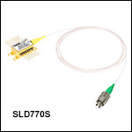
 ズーム
ズーム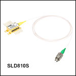
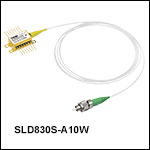
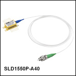
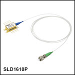
 近赤外域用SLDバタフライ型パッケージ