 Products Home / 半導体レーザ用電流コントローラ(LDドライバ)、温度コントローラ、LDマウント / 光デバイスマウント / ピグテール付き半導体レーザーマウント / ピグテール付き半導体レーザー用マウント
ピグテール付き半導体レーザー用マウント
- Mounts Thorlabs’ Pigtailed LDs
- Compact Housing Protects Pigtail
- Integrated Thermistor and TEC
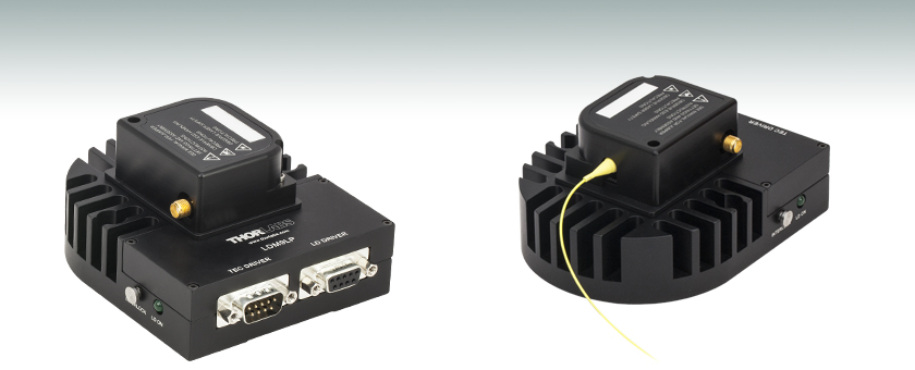
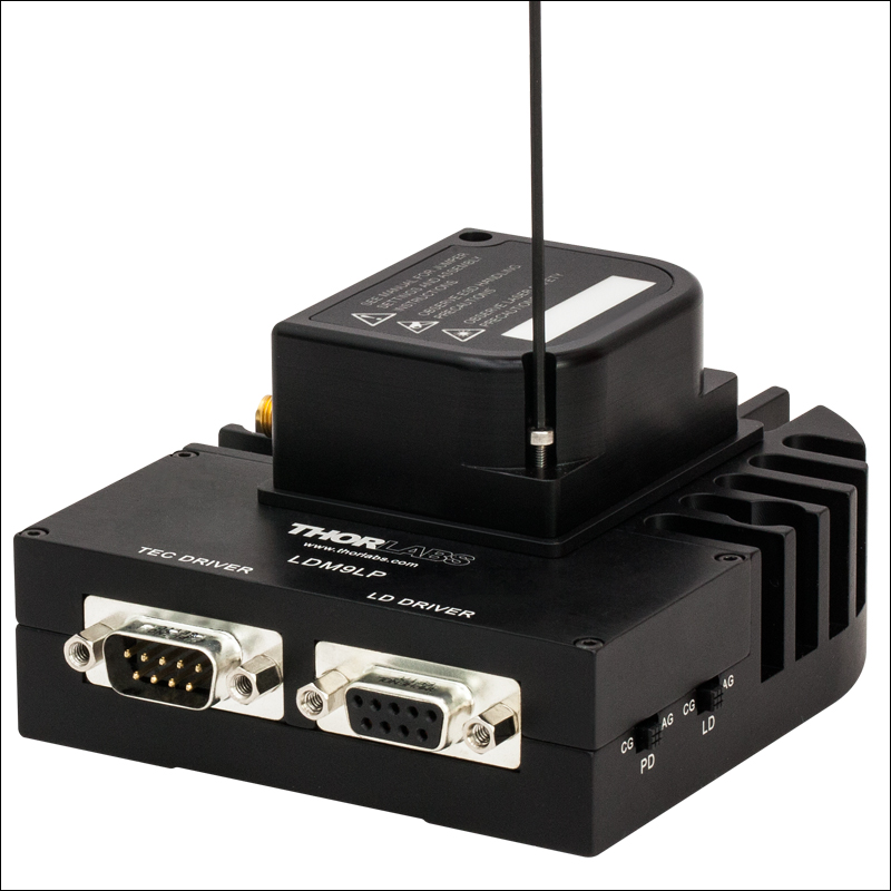
LDM9LP
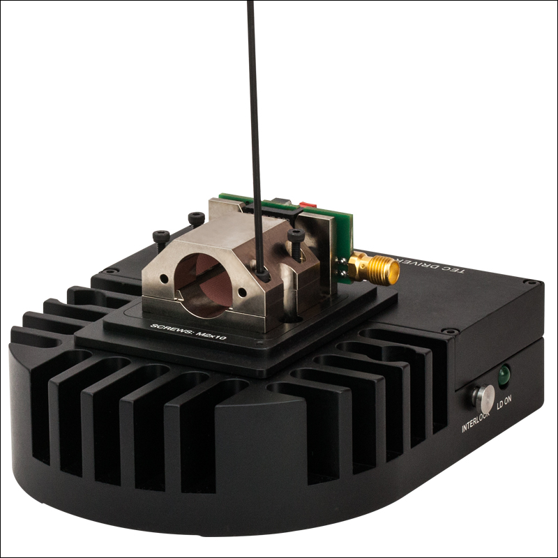
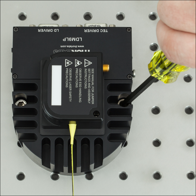
Application Idea
LDM9LP with Mounted
Pigtail Laser Diode


Please Wait


Click to Enlarge
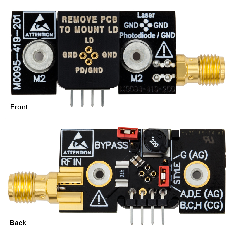
LDM9LPの回路基板。(上)前面(下)背面。
特長
- 当社のシングルモードファイバ、偏波保持ファイバ、マルチモードファイバ、DFBピグテール付き半導体レーザa (Ø5.6またはØ9 mm、3または4ピン)用設計
- A、B、C、D、E、G、Hのピン配列をサポート
- TEC素子による半導体レーザの長寿命化、ならびに出力パワーと波長の安定化
- クラムシェル設計が半導体レーザの温度勾配を除去
- レーザ電流のRF変調用バイアスTアダプタ(>200 kHz)

Click to Enlarge
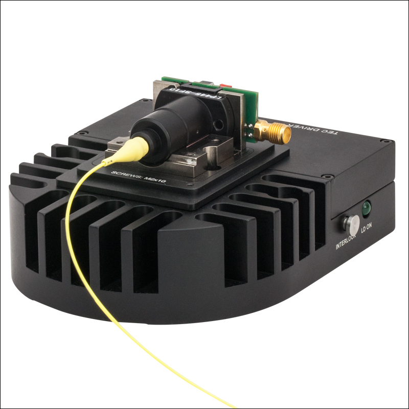
マウントLDM9LP上に取付けられたピグテール付き半導体レーザの拡大写真
LDM9LPは、当社の3または4ピンのピグテール付き半導体レーザaすべてに使用できるよう設計された半導体レーザならびにTECマウントです。 このコンパクトな筐体は、ピグテールを物理的損傷から守り、また優れた温度特性も実現します。 ピグテール付き半導体レーザを動作させるときには、レーザの出力と波長を安定化するために温度制御をすることを強くお勧めします。また温度制御はレーザの長寿命化にもつながります。 一般的な半導体レーザーマウントでの熱伝達は、半導体レーザとマウント冷却板の間の接触に依存しています。 ピグテール付き半導体レーザは、多くの場合ピグテールパッケージの奥に入っているため、標準的な半導体レーザ用マウントに搭載したときには冷却板との接触は良くありません。 しかしLDM9LPは、ピグテール付き半導体レーザに特化した設計となっております。 クラムシェル設計が半導体レーザの温度勾配を低減し、その冷却ブロックがピグテールパッケージを包んでいるため優れた接触と熱伝達を実現しています。 クラムシェル内のピグテールパッケージの周りに放熱グリースを使用すれば、性能はさらに向上します。
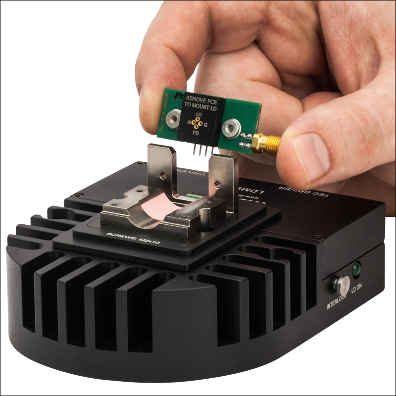
LDM9LPは、ピグテール付き半導体レーザを素早くかつ簡単に取付け・取外しができるマウントです。 回路基板の背面側にはジャンパが付いており、半導体レーザのピン配列を適切に選定することができます(右の写真をご覧ください)。 ジャンパには対応するピンコードが示されているので分かりやすくなっております。 ピグテール付き半導体レーザを取付ける前に、必ずジャンパが正しく設定されているかどうかを確認してください。 また回路基板の前面側にはソケットのピン配列が記載されているので、半導体レーザの取付け方向が分かります(詳細は「取付け方法」をご覧ください)。
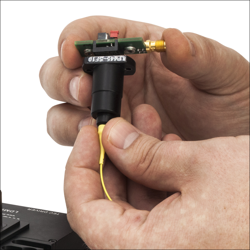
マウントには2つの6.4 mm(1/4インチ)の貫通穴があり、1/4"‑20またはM6キャップスクリュで光学テーブルに固定できます。 ピグテール付きレーザを正しくLDM9LPに取付けた場合、レーザに刻印されている製品番号は通常、左の写真のように上向きになります。 数少ない例外として、LPS-PM1310-FC、LPS-1310-FC、LPS-PM1550-FC、LPS-1550-FCがあります。よって半導体レーザを正しくソケットに取付けるには、レーザのピン配置を確認することは良い習慣であり強くお勧めいたします。 ソケットのピン配列は、カバーの内側、そして回路基板の前面側にも記載されています。
DB9コネクタは、当社の半導体レーザ用電流コントローラならびに温度コントローラすべてに接続できます。 RF SMAコネクタはバイアスT回路に接続されており、レーザ駆動電流にRF変調(>200 kHz)を加えることを可能にしています。 200 kHz未満の変調には、半導体レーザーコントローラで電流を変調します。 リモートインターロックジャックは、シャッタや警告信号などの安全デバイスの接続に使われます。
a. このマウントは当社のピグテール付き半導体レーザ専用に設計されています。 また、このマウントはVHG安定化ピグテール付き半導体レーザにもお使いいただけます。この場合は保護カバーは出来ませんが、半導体レーザの性能には影響ありません。当社では半導体レーザをピグテール化するサービスをご提供しております。詳しくは当社までご連絡ください。詳しくは当社までご連絡ください。
| LDM9LP Specifications | |
|---|---|
| Laser Diode Package | Thorlabs' SM, PM, MM, and DFB Pigtailed Laser Diodes (Ø5.6 or Ø9 mm, 3 or 4 Pin) |
| Supported Pin Configurations | A, B, C, D, E, G, & H |
| Laser Current (Max) | 1 A |
| Laser Diode Polarity | Selectable |
| Monitor Diode Polarity | Selectable |
| LD Interface | DB9, Female |
| RF Power (Max) | 500 mW |
| RF Input Impedance | 50 Ω |
| Modulation Frequency (Bias-T) | > 200 kHz |
| RF Input Connector | SMA |
| TEC Current (Max) | 4.5 A |
| TEC Voltage (Max) | 3.0 V |
| TEC Heating/ Cooling Capacity | 7 W (Mounted to a 12" × 12" Breadboard) |
| TEC Interface | DB9, Male |
| Temperature Sensor | 10 kΩ Thermistor, ±1% at 25°C, β = 3988 |
| Typical Temperature Range (LD Dependent) | 0 to 70 °C -10 to 70 °C (Mounted to a 12" × 12" Breadboard) |
| Remote Interlock | 2.5 mm Phono Jack |
| Dimensions (L × W × H) | 4.48" × 3.5" × 2.1" (113.8 mm × 88.9 mm × 53.3 mm) |
対応するピン配置はLDM9LPのカバーの裏面に記載されています。
対応する半導体レーザーピンタイプの設定
LDM9LPは、A、B、C、D、EならびにGピン配置に対応します。下の図ではそれぞれのピンコードに適合するレーザ取付けPCBのソケットを示しています。右下の写真にある2つのジャンパーピンの設定も必要です。設定は下の表にまとめています。 BYPASSジャンパは、レーザをLDドライバで変調する場合にのみ設定してください。
Click to Enlarge
上のピン配列は、レーザのピンがどのようにレーザ取付けPCBのソケットに整合するかを示しています。

Click to Enlarge
上の写真では、STYLEならびにBYPASSジャンパーピンの位置を示しています。STYLEジャンパーピンは、使用する半導体レーザのピンスタイルに応じて設定する必要があります。BYPASSジャンパは、レーザをLDドライバで変調する場合のみ設定してください。設定は下の表にまとめています。
| STYLE Jumper | |
|---|---|
| Laser Diode Pin | Jumper Position |
| A, B, C, D, E, or H | Lower 2 Pins |
| G | Upper 2 Pins |
| BYPASS Jumpera | |
|---|---|
| Operation Mode | Jumper Position |
| Low Noise, No Modulation | Removed |
| RF Modulation via RF IN (BIAS-T) | Removed |
| Modulation via LD Driver Inputb | Set |
半導体レーザーコネクタ
D型 メス
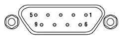
| Pin # | Signal |
|---|---|
| 1 | Interlock and Status Pin (LDC Specific) |
| 2 | Photodiode Cathode |
| 3 | Laser Ground (Case) |
| 4 | Photodiode Anode |
| 5 | Interlock and Status Return |
| 6 | Laser Diode Voltage (-) |
| 7 | Laser Diode Cathode |
| 8 | Laser Diode Anode |
| 9 | Laser Diode Voltage (+) |
TECコネクタ
D型 オス
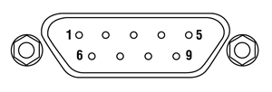
| Pin # | Signal |
|---|---|
| 1 | TEC Lockout (+) |
| 2 | +Thermistor |
| 3 | -Thermistor |
| 4 | +TEC |
| 5 | -TEC and TEC Lockout (-) |
| 6 | Not Connected |
| 7 | Not Connected |
| 8 | Not Connected |
| 9 | Not Connected |
半導体レーザーソケット
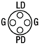
G - Ground
LD - Laser Diode Pin
PD - Photodiode Pin
RF変調
SMAメス
これは、>200 kHzの変調周波数のBIAS-Tネットワークを
通じてレーザに直接AC結合する50 Ωの入力端子です。
Click to Enlarge
上のグラフは、外部コントローラからの変調に対する、LDM9LPのRF変調応答を表しています。データの取得にはベンチトップ型LD電流コントローラLDC202Cを使用しました。

Click to Enlarge
上のグラフは、搭載されているバイアスT SMA入力コネクタからの変調に対する、LDM9LPのRF変調応答を表しています。
Click to Enlarge
ステップ1: 1.5 mm六角レンチ(マウントに付属)またはボール(六角)ドライバを使用して、カバーからネジを外します。
Click to Enlarge
ステップ2: 1.5 mmボールドライバまたは六角レンチを使用して、クラムシェルを固定している4本のネジを外します。

Click to Enlarge
ステップ3: 最後に回路基板を固定している2本の1.5 mm六角ネジを外します。
Click to Enlarge
ステップ4: 回路基板をそっと上に持ち上げ、ソケットから外します。 半導体レーザを取付ける前に、基板の後ろ側のジャンパが正しく設定されていることを確認します(詳細は「仕様 」タブをご覧ください)。
Click to Enlarge
ステップ5: 半導体レーザーピンが正しくアライメントするよう回路基板のピン配列(「仕様 」タブ内)を参照しながら、半導体レーザをソケットに挿入します。 半導体レーザを取扱う際には必ず接地用ストラップ(WS01やWS02など)をご使用ください。
Click to Enlarge
ステップ6: 半導体レーザを取付け後、回路基板を慎重にソケットに差し込みます。 回路基板をしっかり差し込んだ後、ステップ3で外した2本の六角ネジで固定します。

Click to Enlarge
ステップ7: ステップ2で外したネジ4本を取付けます。 熱接触が適切に得られるよう、すべてのネジがぴったりねじ込まれていることを確認してください。

Click to Enlarge
ステップ8: カバーをマウントに固定するネジを締めます。
Click to Enlarge
ステップ9: 最後に、LDM9LPを2つのM6キャップスクリュでブレッドボードまたは光学テーブルに固定します。

Click to Enlarge
LDM9LP Packaging

| Item # | % Weight Reduction |
CO2-Equivalent Reductiona |
|---|---|---|
| LDM9LP | 14.71% | 5.26 kg |
Smart Pack
- Reduce Weight of Packaging Materials
- Increase Usage of Recyclable Packing Materials
- Improve Packing Integrity
- Decrease Shipping Costs
Thorlabs' Smart Pack Initiative is aimed at waste minimization while still maintaining adequate protection for our products. By eliminating any unnecessary packaging, implementing packaging design changes, and utilizing eco-friendly packaging materials for our customers when possible, this initiative seeks to improve the environmental impact of our product packaging. Products listed above are now shipped in re-engineered packaging that minimizes the weight and the use of non-recyclable materials.b As we move through our product line, we will indicate re-engineered packages with our Smart Pack logo.
| Posted Comments: | |
Salem Hegazy
(posted 2023-05-25 07:32:06.94) I purchased the units:
- Mount: LDM9LP
- LD: LP785-SAV50
- LD Controller: LDC205C
However, I have no TEC controller. Please let me know if it is OK to operate this system without the TEC controller. (Or this will damage the LD). In other words, is there a problem (or what are the disadvantages) for not using TEC controller?
Also, If it is OK to operate the system without TEC, is there any JMPR to be plugged/unplugged in the purchased unit, or just let it as it is. cdolbashian
(posted 2023-06-01 02:14:10.0) Good afternoon Salem. While a TEC element/controller is not strictly necessary to use when using such a laser package, it is greatly encouraged. Excessive heat in the package is one of the easiest and fastest ways to reduce the lifetime of your laser element. I have contacted you directly with more information. Eloy Montesinos
(posted 2023-04-27 12:40:53.103) Hello
I'm trying to use this mount (LDM9LP) with the LPSC-1550-FC laser, connected to a third party controller (ILX LightWave LDC-3742 B). I have made a cable to interface according the manual, and still not working, the controller launch a "Open Circuit" alert.
The connections and configurations have been checked and everything is in order. The factory Interlock is installed and the resistor is properly computed and connected, so the status LD is ON state.
What could be the error?
Do you have a detailed scheme of the circuit in the Interlock Pins? ksosnowski
(posted 2023-05-01 09:32:09.0) Thanks for reaching out to Thorlabs. The LDM9LP's Status LED is powered from the interlock line of the connected laser controller, so this implies the Open Circuit error might result directly from an improper connection or setting on the mount or laser controller. When the laser connection is open, the constant current driver attempts to ramp up voltage to meet the setpoint, but due to high resistance, may hits the driver compliance voltage limit first. Wrong polarity of diodes may result in this error as well, and reversing laser polarity can break the diode. Most controllers, have a separate error message for interlock related events, as described in their device manuals. I have reached out directly to discuss this issue further. Adriana Riofrio
(posted 2021-07-24 23:19:14.763) Good evening, we have purchased the LDM9LP but we want to use a controller from another manufacturer (arroyo instruments). We have worked out the current and temperature control wire but we have a 501 message related to the interlock. The 2.5 mm Mono Phono Jack did not come to us, is it necessary to connect it with an external voltage source at 5V? Could you tell me how the circuit should look?
I appreciate your response cdolbashian
(posted 2021-08-19 01:57:47.0) Thank you for contacting us here at Thorlabs! It seems like you are simply missing the interlock pin for your device. I have reached out to you directly to resolve this. Chad Bender
(posted 2020-08-27 16:48:43.677) I am trying to bring back into service an old ITC502 controller. The pinout for the controller LD Driver DB9 appears to match the current pinout for the LDM9LP. However, the TEC has clearly changed in the past decade (controller has a DB15). Does Thorlabs provide a cable that can connect these devices, or will I need to fabricate a custom cable? I can certainly do that - would just prefer to save time if I can buy an COTS cable. MKiess
(posted 2020-08-31 06:55:16.0) Hello Chad, thank you for your inquiry.
The cables that came with the ITC502 are also compatible with the LDM0LP.
The pin configurations of the newer controllers are the same as the ITC502. The matching cables would be the CAB400 for the laser controller and the CAB420-15 for the temperature controller. These cables are still available on our website. Hosung Byun
(posted 2020-05-30 01:31:28.05) Hello, Thorlab!
This is Hosung Byun, graduated student at Seoul National University in Korea.
I bought 'LDM9LP Mount' to operate 'LP635-SF8' diode laser.
And I try to use LDC220C & TED200C for drivers, which are fully functional to LDM56/M.
But I found that TED200C can not detect the sensor, indicating 'no sensor', while LDC220C works.
So I want to know whether TED200C is not compatible to LDM9LP, although it is written "All Thorlabs TED series temperature controllers" in manual.
If not, let me know expected reasons for this and solutions,
or I would like to exchange it.
Thank you.
Kind regards,
Hosung Byun. asundararaj
(posted 2020-06-01 03:04:56.0) Thank you for contacting Thorlabs. The TED200C is compatible with the LDM9LP. Typically, the "NO SENSOR" message would indicate that the temperature sensor is incorrectly selected or not connected. The temperature sensor in the LDM9LP is a 10 kΩ Thermistor. I have contacted you directly to assist further. Hugh Wilson
(posted 2019-04-03 22:09:52.347) Hello,
I would like to ask about the pink/grey pads of material placed in the inside of the clamshell of the LDM9LP (visible in step 3 of the mounting instructions: https://www.thorlabs.com/newgrouppage9.cfm?objectgroup_id=4839&pn=LDM9LP)
Do they have any function or should they be removed prior to applying thermal paste and mounting the diode?
Thank you very much for your help.
Best,
Hugh YLohia
(posted 2019-04-08 03:09:19.0) Hello Hugh, thank you for contacting Thorlabs. This is a thermally conductive pad and is meant to maximize the thermal contact in place of thermal grease. It’s a bit cleaner to use than thermal grease since the connection is designed to be user-serviceable. That being said, you may remove the pad prior to applying thermal grease if it looks like your application produces a high heat load. Bernard Alunda
(posted 2019-03-16 12:45:01.73) Hello,
I have a question regarding the laser diode mount LDM9LP. In chapter of the manual, section about RF modulation, what does the "Use the laser controller to establish the DC operating point of the laser"? I am using LDC501 to drive the laser. Please let me know. Thank you and hoping to hear from you soonest.
Warmest Regards,
Ben llamb
(posted 2019-03-28 09:01:54.0) Hello Ben, thank you for your feedback. That sentence in the manual refers to establishing a center point around which you will be modulating, a point above the laser threshold value in most cases. I have reached out to you directly for any further clarification. jlow
(posted 2012-08-03 16:47:00.0) Response from Jeremy at Thorlabs to Hazen: To mount the pigtail on this, one would set the pigtail down on the bottom copper plate first before slowly trying to get the pins to slide in (mostly done by feel). While this is do-able (but definitely not ideal), the steep viewing angle does make it quite difficult to mount our pigtail in an easy way, which means this would warrant a redesign of the mounting part. We would certainly welcome any additional feedback you are willing to share with us. I will let our engineering group know about this and get started on ideas on improving this mount. hbabcock
(posted 2012-08-03 15:31:02.0) These work well once you manage to get your diode mounted. However in my experience getting your diode in position is a lot more difficult than one would hope. I have on several occasions managed to almost destroy the pins on the diode trying to get them lined up & inserted into the mounting socket. It might be easier if the brass/copper bottom plate was also removable so that you were not forced to come in at such a steep angle?
-Hazen Babcock |