 Products Home
ノイズ減衰器・レーザー強度安定化装置

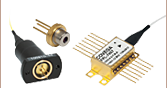
- Laser Amplitude Stabilizer / Variable Attenuator
- Models with Wavelength Ranges Covering 425 - 1620 nm Available
- Internal Closed-Loop Feedback
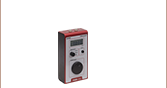
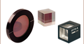
Front
Back
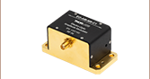
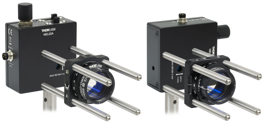
NEL02A Noise Eater with Half-Wave Plate in CRM1T Rotation Mount
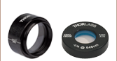
Application Idea
NEL01A
Modulation Input


Please Wait

Click to Enlarge
Noise Attenuation Factor(ノイズ減衰係数)は、ノイズ減衰器を通る前後のノイズ振幅の比率です。
特長
- レーザの強度ノイズを低減
- 可変光減衰器またはEO変調器としても機能
- 425~650 nm、475~650 nm、650~1050 nm、1050~1620 nmのモデルをご用意
- 最大入射光パワー:1.65 W(ただし、モデル、波長、ビームサイズによります。 詳しくは「動作」タブをご覧ください。)
- 光ピンセットなど光パワーに敏感な実験に最適
- CWレーザの安定化に使用可能
当社の液晶ノイズ減衰器・レーザ強度安定化装置は、直線偏光の光強度を安定化、変調、減衰させる装置です。この閉ループシステムは425~650 nm(NEL01A/M)、475~650 nm(NEL02A/M)、650~1050 nm(NEL03A/M)、1050~1620 nm(NEL04A/M)用に設計されています。ローパワー用(<60 mW)ならびにハイパワー用(<1.65 W)をご用意しております。すべて外部変調入力端子付きです。詳細は、「仕様」タブをご参照ください。
ノイズの低減
このノイズ減衰器は、液晶振幅変調器にフォトダイオードによる出力測定とフィードバック制御回路と組み合わせた構成で、直線偏光された光の強度ノイズを取り除き、出力値を0.05%以内の変動値まで安定させます。入射パワーは、ユニットの上部にあるスイッチを使用して、いくつかの範囲の1つに設定できます。これにより、信号出力を不要に減衰することなく、ノイズの除去が可能となります。その後、ポテンショメータを調整して出力パワーを選択します(詳細は「動作」タブをご覧ください)。各モデルの長期的な性能ならびに周波数特性については「性能」タブでご覧になれます。

Click for Details
上から見たNEL02A(/M)のパワーレンジ調整スイッチと変調入力端子

Click to Enlarge
ノイズ減衰器の概略図
出力の減衰と変調
このノイズ減衰器は、液晶リターダと内蔵の偏光フィルタを使用して、レーザ出力の連続的な減衰と変調が可能です。ノイズ減衰器は、ほかの減衰器とは異なり、可動部が無い構成でレーザ出力を急速に減衰させます。ノイズ減衰器の減衰量は、搭載のポテンショメータ、もしくは電気変調入力で制御することができます。
当社のノイズ減衰器はM4タップ穴を使って2方向でポストに取り付けが可能です。また、30 mmケージシステムに取り付けられるよう前面と背面にケージロッド取付け用のタップ穴もあります。後部開口にはØ25 mm~Ø25.4mm(Ø1インチ)レンズチューブに対応するSM1ネジも付いています。
| Item # | NEL01A(/M) | NEL02A(/M) | NEL03A(/M) | NEL04A(/M) | |
|---|---|---|---|---|---|
| Wavelength Range | 425 - 650 nm | 475 - 650 nm | 650 - 1050 nm | 1050 - 1620 nm | |
| Switchable High Power Mode | - | ||||
| Noise Attenuation Performance Specs | |||||
| Output Power Stabilitya | ±0.05% (RMS) | ||||
| Noise Attenuation Frequency Rangeb | DC - 1.8 kHz | DC - 2.5 kHz | DC - 1.4 kHz | ||
| Noise Attenuation Amplitude Range | 0.1% to 50% of Input Signal | ||||
| Noise Attenuation Factorc | > 150 at 10 Hz, 80 at 60 Hz 20 at 400 Hz, 4 at 1 kHz | > 150 at 10 Hz, 80 at 60 Hz 10 at 400 Hz, 1.5 at 1 kHz | |||
| Effective Output Power Attenuation Ranged | 1 - 40 | 1 - 5 | |||
| Internal Polarizer Blocking DamageThreshold (Maximum Power Attenuation) | 1 W/cm2 | 10 W/cm2 | |||
| Attenuation Control | Onboard Potentiometer (10 Turns) or SMA Modulation Input | ||||
| Optical Specs | |||||
| Transmission (Click for Plot) | > 85% at 635 nm | > 80% at 635 nm | > 85% at 780 nm | > 85% at 1550 nm | |
| Power Level Switching | Four Position Power Range Switch | High/Low Power Mode Switch and Four Position Power Range Switch | |||
| Maximum Input Power | See the Max Powers at Various Wavelengths Section on the Operation Tab | ||||
| Minimum Input Power | 0.5 mW | ||||
| Polarization Extinction Ratio at Output | > 1000:1 Over Wavelength Range | ||||
| Damage Threshold (CW)e | 0.8 W/cm2 | 8 W/cm2 | |||
| Input Aperture | Ø5 mm | ||||
| Input Beam Diameterf | Ø4 mm (Max) | ||||
| Output Beam Displacement | 1 mm Vertically (in the Direction of Input Polarization) | ||||
| Beam Divergence | 5 mrad (Max) | ||||
| Angle of Incidence | ±2° (Max) | ||||
| Input Polarization Tolerance | ±3° | ||||
| Wavefront Distortion | ≤ λ/4 at 635 nm | ≤ λ/2 at 635 nm | |||
| AR Coating | Ravg < 0.5% from 400 - 650 nm | Ravg < 0.5% from 650 - 1100 nm | Ravg < 0.5% from 1050 - 1620 nm | ||
| Modulation Performance Specs | |||||
| Modulation Input | SMA Connector, 0 - 2.5 V, 10 kΩ Input Impedance | ||||
| Extinction Ratiog | 512.6 | 7.7 | 6.5 | ||
| Minimum Rise / Fall Timeh | 0.65 ms / 7.3 ms | 0.75 ms / 11.5 ms | 2.8 ms / 25 ms | ||
| Pulsed Laser Input Repetition Rate | > 1 MHz | ||||
| General Specs | |||||
| Mounting Options | Two 8-32 (M4) Tapped Holes for Post Mounting 30 mm Cage System Compatible via Eight 4-40 Tapped Holes Ø1" Lens Tube Compatible via 4 mm Deep Internal SM1 Threads on Rear Side | ||||
| Operating Temperature Range | 15 °C to 45 °C | ||||
ノイズ減衰器の性能グラフ
下のグラフでは、入力パワーレベル、入力信号の変調(ノイズ)振幅、出力信号の減衰、のいずれか1つの変化させたときのノイズの減衰特性をご覧いただけます。 このグラフから、様々なパラメータの変化にかかわらずノイズ減衰器が一定の性能を発揮することがわかります。
グラフの定義
Noise Attenuation vs. Input Power
Noise attenuation factor(ノイズ減衰係数)は、ノイズ減衰器を通る前後のノイズの振幅の比率です。 異なる入力パワーレベルにおけるノイズ減衰係数を信号の変調度(ノイズ振幅)を固定した状態で測定して得られたのが下のグラフです。 このグラフによって、ノイズ減衰器が入射光パワーレベルの変化に影響を受けず、一定の性能を発揮することがわかります。
Noise Attenuation vs. Noise Amplitude
このグラフでは、入力信号はノイズをシミュレーションするため、正弦波で変調されています。 変調(ノイズ振幅)の大きさを変えたときの、ノイズ減衰係数が測定されています。 このグラフによって、ノイズレベルが高い場合であっても、このノイズ減衰器が一定の性能を実現することがわかります。
Noise Attenuation vs. Signal Attenuation
ノイズ減衰器は光制御用の素子として液晶変調器を利用しているため、ノイズの減衰は、ノイズの発生時にレーザ光線を減衰させることで実現させます。 当社のノイズ減衰器は、信号を大きく減衰させることなく、ノイズ減衰性能を最適化する設計です。 このグラフによって、わずか5~10%の出力の損失で、規定のノイズ減衰が達成できることを示し、それ以上の出力損失ではノイズ減衰にあまり変化がないことがわかります。
Modulation Performance
変調入力端子付きのノイズ減衰器は、EO変調器としてもお使いいただけます。 このグラフでは、ノイズの無い入射光に対し、周波数を上げながら、2.5 V振幅の正弦波変調しています。 このグラフによって、最大変調度は変調周波数が上昇するにしたがって低下することがわかります。 さらに試験が行われましたが、変調性能はここでご紹介するノイズ減衰器のモデルでは変調性能はレーザービームの入力パワーにかかわらず一定であることが示されました。
NEL01A/M:ローパワー用ノイズ減衰器、可視域用(425~650 nm)
生データはこちらからダウンロードいただけます。
| Item # | Noise Attenuation | Modulation Performance | Long-Term Noise Attenuation | Transmission | ||
|---|---|---|---|---|---|---|
| vs. Input Power | vs. Noise Amplitude | vs. Signal Attenuation | ||||
| NEL01A(/M) |  |  |  |  |  | |
NEL02A/M:ハイ&ローパワー用ノイズ減衰器、可視域用(475~650 nm)
生データはこちらからダウンロードいただけます。
| Item # | Noise Attenuation | Modulation Performance | Long-Term Noise Attenuation | Transmission | ||
|---|---|---|---|---|---|---|
| vs. Input Power | vs. Noise Amplitude | vs. Signal Attenuation | ||||
| NEL02A(/M) |  |  |  |  |  | |
NEL03A/M:ハイ&ローパワー用ノイズ減衰器、近赤外域用(650~1050 nm)
生データはこちらからダウンロードいただけます。
| Item # | Noise Attenuation | Modulation Performance | Long-Term Noise Attenuation | Transmission | ||
|---|---|---|---|---|---|---|
| vs. Input Power | vs. Noise Amplitude | vs. Signal Attenuation | ||||
| NEL03A(/M) |  |  |  |  |  | |
NEL04A/M:ハイ&ローパワー用ノイズ減衰器、赤外域用 (1050~1620 nm)
生データはこちらからダウンロードいただけます。
| Item # | Noise Attenuation | Modulation Performance | Long-Term Noise Attenuation | Transmission | ||
|---|---|---|---|---|---|---|
| vs. Input Power | vs. Noise Amplitude | vs. Signal Attenuation | ||||
| NEL04A(/M) |  |  |  |  |  | |
ノイズ減衰器の動作
当社の液晶ノイズ減衰器・レーザ強度安定化装置は、レーザ出力を安定化、変調、減衰させる装置です。右の概略図が示すように、ノイズ減衰器は、可変減衰器(液晶可変波長板および偏光フィルタ)、校正済みのビームスプリッタ、そして変調器制御用のサーボコントローラで構成されています。
直線偏光された光は、可変リターダとして機能する液晶リターダに入射し、出力後、偏光フィルタを透過することで、減衰量が制御されます。次にビームスプリッタによりビームのごく一部がフィードバックループに送出されます。このフィードバックループは、フォトダイオードと制御用サーボコントローラで構成されています。サーボコントローラは、送られてきた光信号をあらかじめ設定された信号レベルと比較し、光信号が所定のレベルに達するまで、適当な調整電圧を印加します。
ノイズ減衰器は、可変減衰器としても使用可能です。ポテンショメータの抵抗値を調整することで、必要な光出力レベルを設定できます。
Click to Enlarge
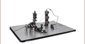
このノイズ減衰器は、入射光の偏光方向に合わせて、2つの異なる向きでポストに取り付けられます。ケージ用回転マウントCRM1T(/M)と4本の30 mmケージロッドで1/2波長板を取り付けると、偏光軸の微調整ができます。
取付けとアライメント
ノイズ減衰器は、その入射開口部付近に刻印された矢印方向でアライメントされている直線偏光を入射する設計です。したがってノイズ減衰器が最良の性能を発揮するために重要なことは、入射光が直線偏光であることと、指定の偏光方向に合った適切なアライメントであることです。
光損失を最小限に抑えるために、ノイズ減衰器は入射部に偏光フィルタを持たない設計になっています。入射光が直線に偏光されていない時には、直線偏光子をノイズ減衰器の前に取り付けて入射光の偏光状態を調整します。
また、直線偏光の入射光が、垂直方向もしくは水平方向に精密にアライメントされていない時は、ノイズ減衰器の前に回転可能な1/2波長板を置くと、入射偏光軸を回転調整することができます。右の写真にあるように、ケージにマウントされたノイズ減衰器をケージ用回転マウントCRM1T/Mと組み合わせて使用すると1/2波長板が回転できるようになり、偏光軸をノイズ減衰器に合わせてアライメントできます。
ノイズ減衰器にはポスト取付け用に2個のM4ネジ穴があります。これらのネジ穴は90°の位置関係に配置されているので、垂直方向または水平方向の偏光軸を持つ光をノイズ減衰器に合わせてアライメントできます。またノイズ減衰器の前部にある4個のタップ穴を利用すると、当社の30 mmケージシステムに減衰器を水平または垂直の方向に組み込むことができます。
このノイズ減衰器で最良の性能を得るには、ビームが開口部の中心近くに入射する必要があります。ノイズ減衰器内部の光路の影響で、ノイズ減衰器が(ポテンショメータが上に向いた)右から2番目の写真のように取り付けた場合、出力光は1.0 mm下にシフトします。同様に右端の写真のようにノイズ減衰器を水平に取り付けた場合、出力光は1.0 mm横にシフトします。
Click to Enlarge
上のグラフは、ノイズのない入射光を、2.5 V振幅で正弦波変調し、その変調周波数を上げていきながら測定されています。

Click to Enlarge
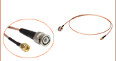
SMA変調入力ジャック
変調
ノイズ減衰器の右側にはSMAコネクタ接続部があり、ノイズ減衰器の減衰量を変調する際にご使用になれます。変調入力ポートの入力インピーダンスは10 kΩです。0~2.5 Vの範囲の電圧を入力することによって、光出力を0~フルパワーまで変調することができます。出力パワーを変調する前に、まず出力パワーレベルのノブを時計回りにいっぱいまで回します(最小出力パワーの設定)。

Click to Enlarge
点線は各ノイズ減衰器の動作波長範囲を示しています。
Click to Enlarge
上から見た光パワーレンジ調整スイッチ
パワーレンジの調整
このノイズ減衰器上面にある選択スイッチは、入射光のパワー範囲の選択に用います。このパワーレンジ選択スイッチでは、ご使用になる実際のレーザ出力の最大値よりも高い値で設定してください。例えば、NEL01A/Mが635 nmで8 mWの入力パワーで使用されている場合、選択スイッチは10 mWの「3」の位置にセットします。仕様については下記の最大パワー表をご覧ください。
ノイズ減衰器NEL02A/M、NEL03A/M、NEL04A/Mには、ケースの上部に、入射パワーレンジの設定のための2つの選択スイッチがあります。Low/Highのパワースイッチを「LOW」に設定すると入射パワーレンジは低い方のセットの1つに設定可能です。「HIGH」に設定すると高い方のセットの1つに設定できます。具体的な値については下記の最大パワー表をご覧ください。なお、ノイズ減衰器NEL01A/MにはLow/Highのパワースイッチは付いておりません。
ノイズ減衰器NEL01A/M、NEL02A/M、NEL03A/Mのフィードバックループにはシリコンディテクタ、NEL04A/Mにはゲルマニウムディテクタが使われています。ディテクタの感度は波長により変わります。したがって選択スイッチの光パワー値はディテクタが対応する波長での使用を前提としています(NEL01A/MとNEL02A/Mは635 nm、NEL03A/Mは780 nm、NEL04A/Mは1550 nm)。波長におけるパワーレンジは感度と反比例の関係にあります(感度が高い場合は、パワーレンジは小さくなります)。右のグラフでは、波長範囲における2つのディテクタの規格化感度を示しています。また下記の表では、各モデルに対し、異なる波長の光を入射した場合のパワー設定値の概算を示しています。
ノイズ減衰器は、設定した目標の光出力となるように、出力設定値より大きな入射パワーを減衰することにより、出力を一定にしてノイズ減衰を実現しています。このように、ノイズ減衰器では、信号の減衰はできますが、増幅は不可能であることから、光出力はノイズを含んだ入射光の最小レベルを超えることはありません。実際には、必要以上に信号出力を減衰させずに全てのノイズを除去するには、出力レベルはノイズがのった信号の最小出力レベルよりも若干低く設定される必要があります。詳細についてはマニュアルをご参照ください。
様々な波長における最大パワー
下の表は、所定の波長ならびにスイッチ設定における各ノイズ減衰器の最大入力パワーの一覧です。この最大パワーレベルはノイズ減衰器のフィードバック回路により決まっています。ただし、いくつかのケースでは、実際のノイズ減衰器の損傷閾値により制限を受ける場合もございます。ハイパワー用ノイズ減衰器(NEL02A/M、NEL03A/M、NEL04A/M)の損傷閾値は8 W/cm2で、入射パワーがØ4 mm開口に均等に分布していると仮定した場合で、1 Wの最大入射パワーに対応します。ローパワー用ノイズ減衰器(NELA01/M)の損傷閾値は0.8 W/cm2で、入射パワーがØ4 mm開口に均等に分布していると仮定した場合で、100 mWの最大入射パワーに対応します。
| NEL01A(/M) Max Power at Various Wavelengths | |||
|---|---|---|---|
| Switch Position | Max Power at 450 nm | Max Power at 550 nm | Max Power at 635 nm |
| 1 mW | 2 mW | 1.5 mW | 1 mW |
| 3 mW | 6 mW | 4.5 mW | 3 mW |
| 10 mW | 20 mW | 15 mW | 10 mW |
| 30 mW | 60 mW | 45 mW | 30 mW |
| NEL02A(/M) Max Power at Various Wavelengths | ||||
|---|---|---|---|---|
| Switch Position | Max Power at 450 nm | Max Power at 550 nm | Max Power at 635 nm | |
| L | 1 | 2 mW | 1.5 mW | 1 mW |
| L | 2 | 6 mW | 4.5 mW | 3 mW |
| L | 3 | 20 mW | 15 mW | 10 mW |
| L | 4 | 60 mW | 45 mW | 30 mW |
| H | 1 | 200 mW | 150 mW | 100 mW |
| H | 2 | 600 mWa | 450 mW | 300 mW |
| H | 3 | 1000 mWa | 750 mWa | 500 mW |
| H | 4 | N/Ab | ||
| NEL03A(/M) Max Power at Various Wavelengths | |||||||
|---|---|---|---|---|---|---|---|
| Switch Position | Max Power at 650 nm | Max Power at 700 nm | Max Power at 780 nm | Max Power at 900 nm | Max Power at 1000 nm | Max Power at 1100 nm | |
| L | 1 | 1.2 mW | 1.1 mW | 1 mW | 0.9 mW | 0.9 mW | 3.3 mW |
| L | 2 | 3.5 mW | 3.3 mW | 3 mW | 2.6 mW | 2.7 mW | 10.0 mW |
| L | 3 | 11.8 mW | 11.1 mW | 10 mW | 8.8 mW | 8.9 mW | 33.3 mW |
| L | 4 | 35.5 mW | 33.3 mW | 30 mW | 26.3 mW | 26.8 mW | 100 mW |
| H | 1 | 120 mW | 111 mW | 100 mW | 86.0 mW | 89.3 mW | 333 mW |
| H | 2 | 355.5 mW | 333 mW | 300 mW | 258.0 mW | 268 mW | 999 mWa |
| H | 3 | 600 mWa | 500 mW | 500 mW | 430.0 mW | 446.6 mW | 1650 mWa |
| H | 4 | N/Ab | |||||
| NEL04A(/M) Max Power at Various Wavelengths | ||||||||
|---|---|---|---|---|---|---|---|---|
| Switch Position | Max Power at 1050 nm | Max Power at 1150 nm | Max Power at 1250 nm | Max Power at 1350 nm | Max Power at 1450 nm | Max Power at 1550 nm | Max Power at 1620 nm | |
| L | 1 | 1.9 mW | 1.6 mW | 1.4 mW | 1.2 mW | 1 mW | 1 mW | 1.6 mW |
| L | 2 | 5.8 mW | 4.8 mW | 4.1 mW | 3.5 mW | 3.1 mW | 3 mW | 4.8 mW |
| L | 3 | 19.2 mW | 16 mW | 13.7 mW | 11.7 mW | 10.4 mW | 10 mW | 16 mW |
| L | 4 | 57.6 mW | 48 mW | 41.1 mW | 35.1 mW | 31.3 mW | 30 mW | 48 mW |
| H | 1 | 190 mW | 160 mW | 137 mW | 117 mW | 104.7 mW | 100 mW | 160 mW |
| H | 2 | 500 mW | 480 mW | 411 mW | 351 mW | 313.4 mW | 300 mW | 480 mW |
| H | 3 | 835 mWa | 800 mWa | 685 mWa | 585 mWa | 520 mWa | 500 mW | 800 mWa |
| H | 4 | N/Ab | ||||||
| Posted Comments: | |
user
(posted 2024-09-17 11:19:51.99) Would be nice to have a TTL to show whether the light is green or red. 赫 王
(posted 2024-07-30 10:00:36.687) 您好,通过光电探测器检测经过NEL03A/M的激光,光信号存在规律波形的调制干扰,调制的频率约为17kHz,请问如何消除这种现象? cdolbashian
(posted 2024-08-14 12:25:37.0) Thank you for contacting Thorlabs. We will reach out to you directly for further discussions. cdolbashian
(posted 2024-08-14 12:25:37.0) Thank you for contacting Thorlabs. We will reach out to you directly for further discussions. Edward Flagg
(posted 2023-07-14 20:03:53.777) I am trying to use a NEL02 as a variable attenuator controlled by the modulation voltage. For this to work, the potentiometer knob must be turned entirely clockwise (CW), otherwise the transmitted intensity will not reach the minimum value. However, if the modulation voltage is too low (maybe 6-8 mV), then when the knob is turned to the CW limit, the transmitted intensity will jump up to some mid-range value and the device stops responding to the modulation voltage input. To "reset" the behavior, the knob must be turned counter-clockwise (CCW) until the intensity increases, then it may be turned back CW again to lower the intensity.
My question is whether this behavior is purposely designed into the device, or whether it is a sign that the device is failing. For example, maybe the potentiometer needs to be replaced. If this is a design choice, is there a way to avoid it? It limits the achievable extinction ratio. cdolbashian
(posted 2023-07-21 02:50:10.0) Thank you for contacting Thorlabs. We have contacted you directly to troubleshoot this issue, as this is not intended to be the behavior of the device. Yaqing Zhang
(posted 2023-05-02 22:05:46.673) Hi, Could you please advise if NEL02A works for my pulsed laser ( >100 mW output, 514 nm center wavelength, ~250 fs pulse duration, 40 MHz rep rate) ? Thanks!
Yaqing Zhang
Michigan State University
yqz@msu.edu jdelia
(posted 2023-05-08 08:30:17.0) Thanks for contacting Thorlabs! The Noise Attenuation Frequency Range of NEL02A is DC-1.8 kHz. The response time of the NEL is much longer than the repetition period of the laser and NEL can be thought of as responding to the pulse's average power, as opposed to its peak power. The noise attenuation performance should be fine considering only the repetition rate. However, the liquid crystal material has large dispersion near 520 nm, and there are also input power limitations of NEL, our NEL might not be a suitable item for your application. Brian Wilmer
(posted 2022-12-05 13:26:56.89) There are images of plots of "Long-Term Performance." Could you provide the raw data for these?
Actually it would be nice to have a plot of signal intensity vs time resolved down to much shorter timescales such as microseconds (even if it cannot stabilize well on this time scale), ms, and seconds.
Perhaps the raw data for a minute or few seconds the users could drill into for whatever resolution they're interested in.
Thank you cdolbashian
(posted 2022-12-15 02:24:31.0) Thank you for contacting Thorlabs. The raw data can be downloaded by clicking on the download link in the upper left corner of the table (which can be found under the "Performance" tab). The sampling interval of the raw data is on the minute scale. For data on shorter time scales, in the first three entries of the table we show the noise attenuation factor as plots versus frequencies, in which the sampling frequency was a few 10kHz (with short enough time). user
(posted 2022-10-11 09:37:50.257) How well does the NEL01A work at 422 nm? I know this is close but just outside the quoted range? cdolbashian
(posted 2022-10-14 03:02:27.0) Thank you for contacting Thorlabs. The working wavelength range of NEL01A is limited by the optics inside. We have reached out to you directly to discuss your laser parameters as well as the potential option for a loan unit. user
(posted 2021-09-30 13:34:50.583) Hello,
How does the regulated CW power level depend on the temperature of the NEL03? i.e. How much can I expect the power level to fluctuate per 1°C fluctuation of the ambient? YLohia
(posted 2021-10-11 04:49:34.0) Hello, thank you for contacting Thorlabs. Please refer to the "Long-Term Noise Attenuation" plot in the "Performance" tab (raw data is available online). The temperature fluctuations could be up to 2-3 ℃. NS .
(posted 2020-08-12 06:51:16.42) I have a 15 mW He-Ne laser (Thorlabs), and I want to reduce the inherent noise (RMS: 0.5%) of this laser. How much noise can you expect if you use the NEL01 or 02 model? YLohia
(posted 2020-08-31 11:38:01.0) Hello, thank you for contacting Thorlabs. Your HeNe laser tubes is not stabilized and the noise at certain frequencies would shift with changes in temperature or other factors. The noise for this HeNe can extend into the MHz range but the NEL series is only intended to stabilize noise in the < 1 kHz range. Laerte Patera
(posted 2019-10-11 11:09:54.81) Is it possible to couple the NEL02 stabilizer
with a NPL64C (640 nm) operated at 60 kHz (pulse of 100 ns, average power: 20 mW) to stabilize intensity fluctuation in the order of seconds/minutes? YLohia
(posted 2019-10-15 08:23:16.0) Thank you for contacting Thorlabs. The NEL02 would provide optimal performance with a pulsed laser such as the NPL64C once the pulse repetition rate is significantly higher than the cut-off frequency of the NEL electronics. The NEL can therefore filter out the fluctuations from the carrier of the pulse laser. Typically, we recommend keeping a rep of rate > 1MHz, but we still expect 60kHz to be sufficient since the cut-off frequency is ~10kHz. cwong3
(posted 2019-02-10 12:46:39.713) Will this stabilizer work with a 1 kHz rep rate pulses? nbayconich
(posted 2019-03-01 11:30:18.0) Thank you for contacting Thorlabs. When the Repetition rate is less than 1MHz, the NELXX will misjudge the peak-power as noise signals and will attenuate them as well. We do not advise using a 1kHz rep rate source or a source with a repetition rate below 1Mhz as these noise eaters will not perform as expected. andrea.volpato
(posted 2019-01-31 10:10:30.217) Is it possible to couple this stabilizer with an ultrafast NOPA output 520-740 nm (30 mW, 3 KHz, 100 fs). The bandwidth is in between LCC3111H and LCC3112H specification. Which model is recommended? nbayconich
(posted 2019-02-28 09:43:44.0) Thank you for contacting Thorlabs. We have some concerns about using femto second lasers with our NEL noise eaters. There will always be broadening of the source caused by the substrate glass and LC material. The liquid crystal material has large dispersion near 520nm.
Another consideration is the laser linewidth, pico second pulses may be fine but femto second pulsed sources will likely be too wide for NEL to control. We currently don't have any performance about fs laser at the moment but we will definitely try to gather more data in the future. sdacha
(posted 2019-01-25 14:32:46.663) Can the NEL04 be used with a YAG Microchip laser at 1064 nm that produces ~1 ns pulses with a max. average power of ~140 mW (max. peak power of ~100 kW)? Does the max power in the specs correspond to max. average power or max. peak power? YLohia
(posted 2019-01-30 08:34:29.0) Hello, thank you for contacting Thorlabs. While we don't have a formal pulsed damage threshold for the NEL04, we do expect 100kW peak power to damage the device. The CW damage threshold is 8W/cm^2. gregory.hoth
(posted 2018-10-23 15:38:40.257) Is it possible to use the modulation input of these noise eaters to control the DC power level?
It would be useful to have electronic control of the power transmitted by the noise eater. nbayconich
(posted 2018-11-15 10:20:15.0) Thank you for contacting Thorlabs. Yes it is possible to modulate the input of the noise eaters in order to control the DC power level using the SMC interface, The noise eater can also be used as a variable attenuator, even without the presence of noise. A voltage ranging from 0 to 2.5 V can be input to modulate the output power as needed.
Please note that the output power cannot be modulated higher than the initial input power. The noise eater operates by varying how much of the signal is attenuated in order to reach the target output power and attenuate the noise. Since the noise eater can attenuate the signal but not amplify it, the clean output beam can only have a power as high as the minimum power level of the noisy signal. vytautas.purlys
(posted 2015-10-05 06:39:56.403) 1. Is it possible to use the noise eater for 400kHz - 80Mhz repetition rates of fs lasers? I need to stabilize the laser power for long durations (up to a few days), I don't need to stabilize the pulse-to-pulse stability.
2. How does the EO version work? Is the active element an electrooptical crystal or is it still liquid crystal based? besembeson
(posted 2015-10-13 08:33:51.0) Response from Bweh at Thorlabs USA: These are ideal for CW lasers so it should be suitable at the higher repetition rates (close to 80MHz) but may not be suitable at the lower repetition rates. Also ensure the peak powers are within the limits we specify. The EO version has the same configuration, using a liquid crystal retarder and polarizer. We use the term EO since these have a modulation input that allows system to act as an optical switch. max.ulbrich
(posted 2015-08-29 15:13:13.107) I have a 80mW, 561nm laser which has quite some fluctuations in intensity that I want to reduce. The beam diameter is 0.7mm 1/e2. Which product should I use? Can I keep the beam diameter or do I need to expand it before it passes the device?
Thanks, Max mthrossell
(posted 2015-09-10 06:04:01.0) Response from Matt at Thorlabs USA: We will contact you directly through our Germany office to discuss your application. forget
(posted 2015-06-10 16:59:04.63) What is the time response of the photodiode + amplifier ? Would the LCC3112H/M be usable on a 100 kHz laser at 1030 nm ? Thanks in advance for your answer.
Nicolas besembeson
(posted 2015-09-21 09:21:27.0) Response from Bweh at Thorlabs USA: The response time for the photodiode and amplifier is about 0.35us. The attenuation will be worse than specified so it may not be suitable. In certain cases such as lasers having spikes or step-like output power fluctuations the device may not be able to completely eliminate high frequency noise. pan
(posted 2015-04-07 07:43:26.793) Used LCC3112H on a Ti:Sa laser with 80MHz repetition rate, 800nm. Added noise eater to a beam path with 155mW max power output after the unit, tune to have 145mW output. Tested with PM100 for 10+ hours. See worse power stability with the noise eater. 10 hour drift on the order of ~3%.
Would appreciate comments/suggestions. jlow
(posted 2015-04-17 01:14:25.0) Response from Jeremy at Thorlabs: We will contact you directly to troubleshoot this. elharel
(posted 2014-08-14 13:32:15.683) Can the noise eater handle femtosecond pulses? What is the thickness of the beam splitter? I am concerned about significant dispersion caused by the device.
thanks besembeson
(posted 2014-08-21 02:54:28.0) Response from Bweh at Thorlabs USA: The damage threshold is 10MW/cm^2 peak power and 8W/cm^2 for CW. You can compare your power density to these values. Regarding the dispersion, I will followup with you by email to determine which unit you are interested in, so that I can provide you information about the thickness and dispersion. emeyersc
(posted 2013-11-08 10:13:44.257) Can the IR noise eater handle picosecond pulses from an OPO and still stabilize? What would be the damage threshold in this case (specifically, 1620 nm, 80 MHz, 3 ps)? jlow
(posted 2013-11-12 10:34:37.0) Response from Jeremy at Thorlabs: Since 80MHz is much higher than the bandwidth of the noise eater (2.5kHz), the LCC3113 should still stabilize. The damage threshold is around 10MW/cm^2 peak power and 8W/cm^2 for CW. tcohen
(posted 2012-11-12 13:05:00.0) Response from Tim at Thorlabs to Gediminas: Thank you for contacting us! A 650-1100nm edition of our noise eater is currently in the works and will be released shortly. For your review, we will contact you with more information on this new product. gediminas.dauderis
(posted 2012-11-12 02:01:19.23) Dear Sir/Madan,
Do you have some equipment like Liquid Crystal Noise Eater / Laser Stabilizer 1000 nm wavelength?
Yours Faithfully,
Gediminas Dauderis tcohen
(posted 2012-11-07 21:29:00.0) Response from Tim at Thorlabs: This is correct. The noise attenuation falls off as frequency increases in the target bandwidth to 2.5kHz for this LC design. If you would be interested in a high bandwidth design we would love to discuss this with you as a possible future customer inspired product. mlau
(posted 2012-10-31 21:15:06.233) If I'm reading the noise eater specs correctly, the attentuation falls with high frequency? Is that right? tcohen
(posted 2012-07-09 13:06:00.0) Response from Tim at Thorlabs: The Noise Eater will be released soon. We should be able to assemble a 100mW version but the max beam diameter for this version is 4mm. john.burke
(posted 2012-07-05 18:41:06.0) When will this be available? Is there any chance I could get a custom one with a larger aperature and power handling? I need about 100 mW so an aperature twice radius should be helpful. I could be willing to sacrifice bandwidth for long term stability and power handling.
Thanks! |