超短パルスレーザー用低群遅延分散(GDD)ミラー、970 nm~1150 nm
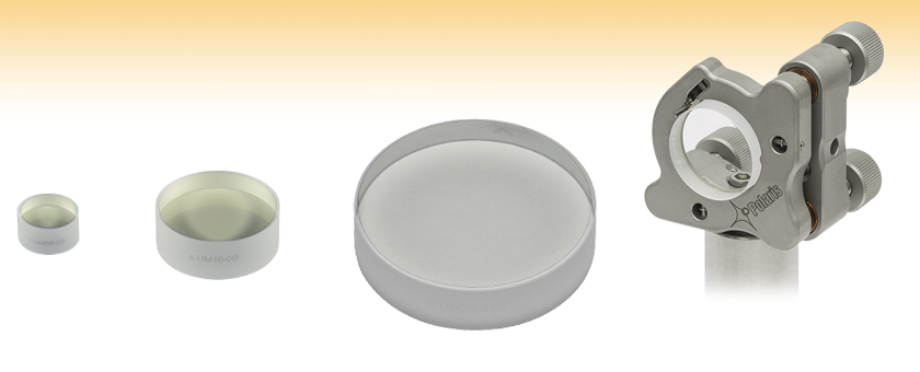
- Ideal for 1st Harmonic of Yb:Glass, Yb:YAG, and Nd:YAG Lasers
- High Reflectance Over 990 - 1120 nm (0° AOI) or 970 - 1150 nm (45° AOI)
- Group Delay Dispersion: |GDD| < 30 fs2
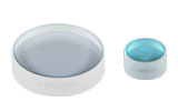
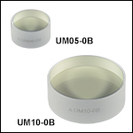
UM10-0B
(Ø1", 0° AOI)
UM05-0B
(Ø1/2", 0° AOI)
Application Idea
UM10-45B Low-GDD Mirror in a Previous-Generation Polaris® Mirror Mount
UM20-45B
(Ø2", 45° AOI)

Please Wait
特長
- 低群遅延分散:: |GDD| < 30 fs2
- 250 fsより短いパルスに適した製品
- 99%以上の反射率
- 入射角(AOI)0°または45°用に設計
- ご提供サイズ
- 入射角0°: Ø12.7 mm(Ø1/2インチ)、Ø25.4 mm(Ø1インチ)
- 入射角45°: Ø12.7 mm(Ø1/2インチ)、Ø25.4 mm(Ø1インチ)、Ø50.8 mm(Ø2インチ)
低群遅延分散(GDD)ミラーには、近赤外(NIR)域で高反射率が得られるコーティングが施されています。波長範囲はイッテルビウム(Yb) およびネオジム(Nd)レーザ用に最適化されています。これらのミラーは、パルスの広がりが問題となるような場合にご利用いただくと有用です。入射角としては0°用(型番末尾が-0B)と45°用(型番末尾が-45B)がございます。誘電体コーティングはイオンビームスパッタリング(IBS)技術で蒸着されています。この技術は制御性に優れ、耐久性の高い誘電体薄膜コーティングを形成できます。
これらのミラーは、反射率>99%、および|GDD|< 30 fs22という性能を両立しています。詳細には「グラフ」タブをご参照ください。
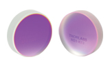
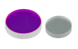
低GDDミラーのサイズは、入射角0°用としてØ12.7 mm(Ø1/2インチ)およびØ25.4 mm(Ø1インチ)、入射角45°用としてØ12.7 mm(Ø1/2インチ)、Ø25.4 mm(Ø1インチ)およびØ50.8 mm(Ø2インチ)をご用意しております。各ミラーのエッジには型番とコーティング面を示す矢印が刻印されています。Ø12.7 mm(Ø1/2インチ)およびØ25.4 mm(Ø1インチ)ミラーの裏面は研磨されているため、反射コーティングを通り抜けた僅かな光をパワーモニタリングなどにご利用いただけます。
当社ではこちらでご紹介している低GDDミラーのほかにも様々な波長域用の低GDDミラーをご提供しています。イッテルビウム(Yb)およびネオジム(Nd)レーザの第2高調波用のミラーについては、超短パルスレーザ用低群遅延分散ミラー、460~590 nmのページをご覧ください。超短パルスレーザ用光学素子のラインナップについては「超短パルス用光学素子」タブをご覧ください。
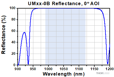
低GDDミラーUMxx-0B、990~1120 nm、入射角0°
Click to Enlarge
生データはこちら
このグラフは反射率の波長依存性(理論値)を示しています。これらのミラーには光を垂直に入射するため、反射率の偏光による変化はありません。青い網掛け領域は、反射率>99%の仕様を満たす波長範囲を示しています。 なお、この仕様波長範囲以外における反射率は典型値であり、特に変動や傾斜のある領域では製造ロットによって変化する場合があります。
Click to Enlarge
生データはこちら
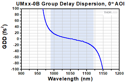
このグラフは、群遅延分散(GDD)の理論計算値を示しています。青い網掛け領域は、GDDの仕様が定められている波長範囲990 nm~1120 nmです。これらのミラーには光を垂直に入射するため、GDDの偏光による変化はありません。
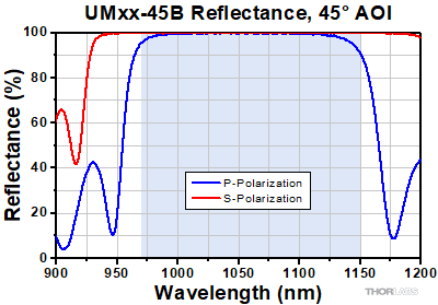
低GDDミラーUMxx-45B、970~1150 nm、入射角45°
Click to Enlarge
生データはこちら
このグラフはS偏光およびP偏光両方の反射率の波長依存性(理論値)を示しています。青い網掛け領域は、RS > 99%の仕様を満たす波長範囲を示しています。 なお、この仕様波長範囲以外における反射率は典型値であり、特に変動や傾斜のある領域では製造ロットによって変化する場合があります。
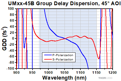
Click to Enlarge
生データはこちら
このグラフは、群遅延分散(GDD)の理論計算値を示しています。青い網掛け領域は、GDDの仕様が定められている波長範囲970~1150 nmです。S偏光の仕様波長範囲の外部では、GDD値は急激に変動しています。
当社では、Nd:YAGレーザ用に最適化した光学素子を幅広くご用意しています。詳細は下記をご参照ください。
| Posted Comments: | |
XIZE Gao
(posted 2024-02-07 19:50:13.597) Dear Thorlabs team. I wonder if the reflectivity and GDD fluctuate greatly with the angle of incidence, when the angle of incidence is less than 6 degrees? Thank you. cdolbashian
(posted 2024-02-16 11:37:51.0) Thank you for reaching out to us with this inquiry! We would not expect the GDD and reflectivity to vary much with such a small change in AOI. I have contacted you directly to discuss this further. Egor Manuylovich
(posted 2021-12-16 12:17:05.037) Dear Thorlabs team,
Could you provide me with the reflectance and GDD for AOI = 0°, please?
Kind regards,
Egor YLohia
(posted 2021-12-23 01:11:03.0) Hello, additional data for these mirrors can be requested by emailing techsupport@thorlabs.com. I have reached out to you directly with a theoretical estimate. slm9
(posted 2014-08-22 11:24:18.123) Dear Thorlabs-Team
Do you have some specs for this coating if this mirror will be used under AOI 0°? I would like to know the spectral shift and the low GDD behavior @AOI 0°.
Thanks and with best regards
Markus besembeson
(posted 2014-08-25 06:25:53.0) Response from Bweh at Thorlabs USA: We have theoretical plots for the reflectivity and GDD when used at 0 deg in comparison to 45 deg. Our European office will followup with you by email regarding this. strotherj
(posted 2014-03-26 15:43:56.47) It would be nice to have mirror that would do 850nm to 1050nm, these are the wavelengths used for imaging fluorescent proteins. At present we use protected silver mirrors, and just accept that we lose most of our light in the mirrors. besembeson
(posted 2014-03-27 04:51:45.0) Response from Bweh E at Thorlabs: Thanks for contacting Thorlabs. We would look into your suggestion of having a low GDD mirror that will cover the 850nm to 1050nm range. |
フェムト秒パルスレーザ用ならびにピコ秒レーザ用光学素子を幅広くご用意しています。詳細は下表をご参照ください。
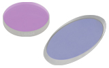
| Dielectric Mirror | High-Power Mirrors for Picosecond Lasers | Metallic Mirrors | Low-GDD Pump-Through Mirrors | ||
|---|---|---|---|---|---|
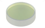 | 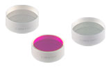 | 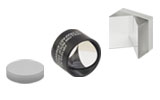 | 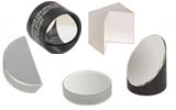 | 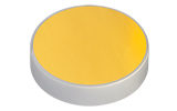 | 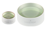 |
| Dual-Band Dielectric Mirror, 400 nm and 800 nm | Ytterbium Laser Line Mirrors, 250 nm - 1080 nm | Ultrafast-Enhanced Silver Mirrors, 750 - 1000 nm | Protected Silver Mirrors, 450 nm - 20 µm | Unprotected Gold Mirrors, 800 nm - 20 µm | Pump-Through Mirrors, 1030 - 1080 nm and 940 - 980 nm |
| Deterministic GDD Beamsplitters | Low-GDD Harmonic Beamsplitters | Low-GDD Polarizing Beamsplitters | β-BBO Crystals | Dispersion-Compensating Optics | |
|---|---|---|---|---|---|
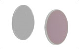 |  |  | 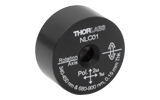 | 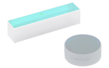 | 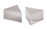 |
| Beamsplitters & Windows, 600 - 1500 nm or 1000 - 2000 nm | Harmonic Beamsplitters, 400 nm and 800 nm or 500 nm and 1000 nm | High-Power, Broadband, High Extinction Ratio Polarizers, 700 - 1300 nm | β-BBO Crystals for Second Harmonic Generation | Dispersion-Compensating Mirrors, 650 - 1050 nm | Dispersion-Compensating Prisms, 700 - 900 nm |

| Item # | UM05-0B | UM10-0B |
|---|---|---|
| Design Wavelength Range | 990 - 1120 nm | |
| Diameter | 1/2" (12.7 mm) | 1" (25.4 mm) |
| Diameter Tolerance | +0.00 / -0.10 mm | |
| Clear Aperture | > 80% of Diameter | |
| Thickness | 6.4 mm (0.25") | 9.5 mm (0.37") |
| Thickness Tolerance | ±0.20 mm | |
| Reflectance | R > 99% | |
| Angle of Incidence | 0° | |
| Group Delay Dispersion | |GDD| < 30 fs² | |
| Laser Induced Damage Thresholda | 0.40 J/cm2 (1030 nm, 309 fs FWHM, S-Pol, 1000 Pulses) | |
| Substrate | Fused Silica | |
| Front Surface Flatnessb | λ/6 | |
| Front Surface Quality | 15-5 Scratch-Dig | |
| Parallelism | ≤3 arcmin | |
| Back Surface | Polished | |

| Item # | UM05-45B | UM10-45B | UM20-45B |
|---|---|---|---|
| Design Wavelength Range | 970 - 1150 nm | ||
| Diameter | 1/2" (12.7 mm) | 1" (25.4 mm) | 2" (50.8 mm) |
| Diameter Tolerance | +0.00 / -0.10 mm | ||
| Clear Aperture | > 80% of Diameter | ||
| Thickness | 6.4 mm (0.25") | 9.5 mm (0.37") | 12.0 mm (0.47") |
| Thickness Tolerance | ±0.20 mm | ±0.10 mm | |
| Reflectance | Rs > 99% (970 - 1150 nm) Rp > 99% (1020 - 1080 nm) | ||
| Angle of Incidence | 45° | ||
| Group Delay Dispersion | |GDDs| < 30 fs² (970 - 1150 nm) |GDDp| < 30 fs² (1020 - 1080 nm) | ||
| Laser Induced Damage Thresholda | 0.40 J/cm2 (1030 nm, 309 fs FWHM, S-Pol, 1000 Pulses) | ||
| Substrate | Fused Silica | ||
| Front Surface Flatnessb | λ/4 | λ/6 | < λ/3 |
| Front Surface Quality | 15-5 Scratch-Dig | 20-10 Scratch-Dig | |
| Parallelism | ≤3 arcmin | ≤5 arcmin | |
| Back Surface | Polished | Fine Ground | |
 Products Home



 ズーム
ズーム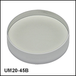
 低GDDミラー、