 Products Home
蛍光または液晶アライメントターゲット

- Fluorescing and Liquid Crystal Targets for Wavelengths from UV to MIR
- Central Hole or Target Aids Alignment
- Available Unmounted, in RMS- or SM-Threaded Housing, or as Cage-Compatible Plates
VRC6SCPT
MIR Alignment Plate
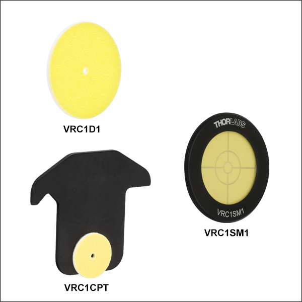
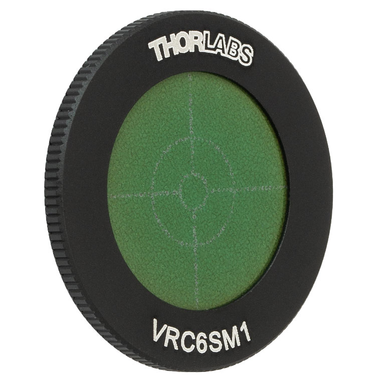
VRC1SM1
SM1 UV/Visible Alignment Disk
VRC4D05
Ø1/2" IR
Alignment Disk
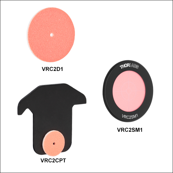
VRC2D1
Ø1" Visible/IR
Alignment Disk
VRC4CPT
Placed in a 30 mm
Cage System
ADF1
Ø1" Visible Blue
Alignment Disk
ADF10
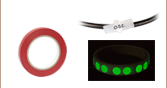
Ø1" Visible Red
Alignment Disk
SCPA2
Orange 16 mm Cage Alignment Plate


Please Wait
| Alignment Target Selection Guide | |||
|---|---|---|---|
| Spectral Region | Absorption Band | Emission Band | Material |
| UV/Visible | 250 - 540 nm | 450 - 750 nm | Fluorescing Slow-Fading Phosphor |
| UV/Visible | - | Orange | Fluorescing Cast Acrylic (Cage-Mountable Plates) |
| UV/Visible | - | Blue, Green, Yellow, Orange, and Red | Fluorescing Cast Acrylic (Unmounted or Threaded Disks) |
| Visible/IR | 400 - 640 nm and 800 - 1700 nm | ~580 - 750 nm | Fluorescing Slow-Fading Phosphor |
| IR | 790 - 840 nm, 870 - 1070 nm, and 1500 - 1590 nm | ~520 - 580 nm | Fluorescing Slow-Fading Phosphor |
| Mid-IR | 1500 - 13200 nm | N/A | Thermochromic Liquid Crystal |
特長
- 難退色性蛍光ディスク、UV~赤外(IR)光のアライメント用
- マウント無し:Ø12.7 mm(Ø1/2インチ)およびØ25.4 mm(Ø1インチ)をご用意
- マウント済み:外ネジ付き筐体または30 mmケージシステム用ドロップイン式アライメントプレートにマウント
- 16 mm、30 mm、60 mmケージ用アライメントプレート、蛍光アクリル製
- Ø25.4 mm(Ø1インチ)の蛍光アクリル製ディスク、UV~赤外光のアライメント用
- 液晶アライメントディスク、中赤外(MIR)光用、SM1ネジ付きまたはケージプレート取付け型
アライメントディスクやアライメントプレートは蛍光材料または液晶で作られており、紫外(UV)域から中赤外(MIR)域のビームのアライメントにお使いいただけます。
Ø12.7 mm(Ø1/2インチ)およびØ25.4 mm(Ø1インチ)の難退色性蛍光ディスクとしては、マウント無しの製品のほかに、SM1またはRMSネジ付き筐体、あるいはドロップイン式のケージプレートに取り付けられた製品をご用意しております。マウント無しのディスクとケージプレート取付け型ディスクの中心にはØ1.5 mmの貫通穴が開いていますが、ネジ付きディスクにはアライメント用ターゲットが付いています。下のグラフでは当社の蛍光ディスクの吸収帯と発光帯を示しています。退色しにくい蛍光材料として、当社のレーザ用ビュワーカード(センサーカード)と同じものを使用しています。
Ø25.4 mm(Ø1インチ)の蛍光アクリルキャスト材のディスクは、青、緑、黄、オレンジ、赤の5色でご用意しています。ターゲットガイドライン付きと中心穴付きの2種類がございます。当社では、16 mm、30 mm、60 mmケージシステム用として、オレンジ色の蛍光アライメントプレートもご用意しております。これらのディスクやプレートの蛍光スペクトルは様々な蛍光色素のスペクトルに近いため、蛍光イメージングに使用される様々なレーザのアライメント用として適しています。
中赤外(MIR)光用の液晶アライメントディスクには、ドロップイン式ケージプレートに取付けられているタイプ(感光部:Ø10.0 mm)と、SM1ネジ付きのタイプ(感光部:Ø20.0 mm)がございます。
その他のアライメント用ターゲット
当社の蛍光材料や液晶を用いたアライメント用ターゲットは、当社の可視光用のアライメントターゲットがベースとなっています。

レーザービームをアライメントする方法
レーザを光学系に取り付ける場合、まず行うべきは、所望の光路設定をするためビームの水平度と方向を調整することです。このようにして設定されると、ビームをうまく迂回させてシステム内の光学素子を透過するように誘導できるだけでなく、システムのアライメントを調整することによって得られる結果が予測しやすくなり、再現性が高くなります。下記のセクションではそれぞれの方法について説明しています。
実験および機器についての「Insights-ヒント集」はこちらからご覧いただけます。
レーザービームのポインティング角度を水平にアライメントする方法
0:00 - はじめに
1:25 - レーザービームのポインティング角度を水平にし、アライメントする方法
4:09 - ビームを迂回させて任意の光路にアライメントする方法

Click to Enlarge
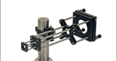
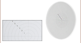
図2: ビームは、光学テーブルのタップ穴のラインに対して平行になるようアライメントすることができます。キネマティックマウントのヨー調整でビーム角度を調整し、ルーラをタップ穴のラインに沿ってスライドさせるときに、ビームの照射位置が横方向で動かないようにします。

Click to Enlarge
図1: :ビーム方向を光学テーブルの表面に対して水平にするには、レーザ用キネマティックマウントのピッチ調整を使用します(図2)。ビームがテーブル表面に対して平行になっている状態は、ビーム高がレーザ前面に近い位置(左)と遠い位置(右)でパワー測定値が同じであることを確認することで行います。
キネマティックマウントのピッチ(チップ)とヨー(ティルト)を調整することで、レーザ角度の微細な補正を行うことができます。この角度調整は、コリメート光を光学テーブル表面などの基準面に対して、あるいはテーブルのタップ穴のラインに沿ってなど基準面内の特定の方向に対してアライメントするときなどで行います。
マウントのアジャスタを使用する前に
まず、キネマティックマウントの各アジャスタを回して移動範囲の中央に移動させます。これにより調整範囲が足りなくなるリスクが少なくなります。また調整範囲の真ん中にアジャスタがあると、マウントのポインティング安定性が良くなります。
その後、レーザを支えるポストやポストホルダなどのオプトメカニクス部品を調整することで、レーザの高さ、位置、向きの粗調整を行います。 調整後はすべてのロックネジが締め付けられていることを確認してください。
ビームをテーブル表面に対して平行にする場合
レーザ光のレベル調整のため、アライメントツールを用いて、マウントのピッチアジャスタによる微細な調整を繰り返す必要があります。
まず光源から近い位置と遠い位置のビームの高さを測定します(図1)。2つの間の距離が長ければ長いほど、確度は高くなります。2つの位置のビーム高が一致するまで、キネマティックマウントのピッチを繰り返し調整します。
ピッチ調整により光源の高さも変わります。動画の例では、光源に近いビーム高は当初82 mmでしたが、最初のピッチ調整で83 mmに上がっています。
ビームを水平に調整した後は、レーザを支えるオプトメカニクス部品を所望の高さに調整します。または2つのステアリングミラーをレーザの後ろに置き、違う方法でアライメントすることもできます(詳細については同セクション内に記載されています)。ステアリングミラーは特に装置自体の角度調整が難しいレーザ装置のビームの高さと方向の調整に有用です。
ビームをタップ穴列に沿った向きに調整
ビームをテーブルのタップ穴列に対して平行にアライメントする場合もアライメントツールとマウントのヨーアジャスタの反復調整が必要になります。
アライメントツールにより、タップ穴列を基準線として、レーザ出力方向を調整できます。ルーラの底辺の端をタップ穴列に合わせて配置します(図2)。
テーブル上の基準線に対するビームの角度ズレは、ルーラに照射されるレーザースポット位置とルーラの垂直基準線の差を見ることで確認できます。取付けブラケットBHMA1を使用して水平置き型のルーラを取り付けることができます。
動画では、ルーラをタップ穴列に並行に移動し、レーザ照射位置をルーラーの1 mm単位の目盛の端に一致させるようにアライメントします。ルーラを基準線の遠い方の位置に移動させると、ルーラのビーム位置も水平方向に移動します。ルーラを遠い方の位置に配置した後、ビーム端が1 mm単位の目盛に一致するまでマウントのヨーを調整します。その後ルーラを光源の近くに移動させ、ビームの位置調整の結果を見ます。このプロセスは必要に応じて反復で行われています。
ビームを迂回させて任意の光路に沿ってアライメントする方法
1つ目のステアリングミラーは、新しい光路上に配置された2つ目のミラーに向けてビームを反射します。2つ目のステアリングミラーは、新しい光路に沿うようにアライメントします。2つのステアリングミラーでレーザ光をアライメントする手順は、Walking the Beam(ビームの移動)として説明することがあり、その結果はFolded Beam Path(折りたたまれたビーム路)と呼ばれることがあります。上の動画の例では、ビームを新しい光路にアライメントするために2つのアイリスが使用されています。新しい光路は光学テーブル面に対して平行で、タップ穴列に沿っています。

Click to Enlarge
図3: 1つ目のミラーから反射されたビームは、x軸ならびにy軸まわりに、それぞれθおよびψ回転すれば、2つ目のミラーに入射します。どちらの角度も2つ目のミラーの中心位置(座標x2、y2、z2 )に影響を及ぼします。1つ目のミラーのx軸周りの回転は、マウントのピッチ(チップ)アクチュエータの移動範囲によって制限されますが、その移動範囲は、2つ目のミラーの位置と高さも制限します。

Click to Enlarge
図5: 2つ目のキネマティックミラーマウントのアジャスタは、2つ目のアイリスにビームをアライメントするのに使用します。

Click to Enlarge
図4: 1つ目のキネマティックミラーマウントのアジャスタを調整して、1つ目のアイリスの開口部にレーザースポットを合わせています。
ミラーの高さの設定
1つ目のミラーの中心は、入射路の高さと一致させます。2つ目のミラーの中心は、新しい光路の高さに合わせてください。
アイリスのセットアップ
新しい光路はアイリスによって設定されます。動画では光路がテーブル面に対して水平となるよう、アイリスの高さが一致していることがご覧いただけます。マウント内のアイリスの高さはルーラかノギスを使用すると適度な精度で設定可能です。
アイリスが閉じているときの(小さな)開口部は、完全な中心位置にない場合があります。そのため、アイリスのビームの入力面をひっくり返すと、開口の位置がシフトする場合があります。アイリスのビーム入力面を決めたらセットアップから使用まで同じ面を使用することを推奨します。
コンポーネントの配置と粗調整
まず、両ミラーのアジャスタを回しながら移動範囲の中央に移動させます。1つ目のミラーは入射光路に配置し、2つ目のミラーは新しい光路上に配置します(図3)。1つ目のミラーのピッチ(チップ)アクチュエータの移動範囲がx周りのミラーの回転(θ )を制限するため、ミラー配置は1つ目のミラーのピッチ(チップ)アクチュエータの移動範囲によって限定されます。2つ目のミラーの位置(x2 、y2 、z2 )を選ぶときは、ピッチに加え、1つ目のミラーのヨー(ティルト)も考慮しなければなりません。2つのミラーは、1つ目のミラーの両アジャスタを移動範囲いっぱいに回さなくてすむよう配置してください。
新しい光路に2つ目のミラーを配置後、両方のアイリスを光路上に置いてください。1つ目のアイリスは2つ目のミラーの近くに、2つ目のアイリスは2つ目のミラーからできるだけ遠くに配置してください。
2つのミラーの高さはそのまま維持し、またヨーのアジャスタは触らずに1つ目のミラーを回転させて、光を2つ目のミラーに向けます。1つ目のミラーのピッチアジャスタを調整して、レーザースポットを2つ目のミラーの中心近くに移動させます。その後、2つ目のミラーを回転させて、ビームを新しい光路にある程度向けます。
最初に光路上に光を当て、その後、向きを調整します。
1つ目のミラーは、2つ目のミラー上にある新しい光路上の点に向けてビームをステアリングするために使用します。まず、1つ目のアイリスに当たるレーザースポットの位置を見ながら1つ目のミラーのアジャスタを調整します(図4)。アイリスの開口部の中心にレーザースポットが合えば最初のステップは終了です。
次に2つ目のミラーでビームをステアリングして、新しい光路とアライメントさせます。2つ目のミラーのアジャスタを調整して、レーザースポットを2つ目のアイリスの開口部に移動します(図5)。ピッチアジャスタがビームの高さを調整し、ヨーアジャスタがビームを横方向に移動します。2つ目のアイリスでレーザースポットが消えてしまう場合、2つ目のミラーのレーザースポットが新しい光路から離れています。
1つ目のミラーのアジャスタを調整しながら2つ目のミラー上のビーム位置を変え、1つ目のアイリスの開口部の中心にレーザースポットがあたるようにします。2つ目のミラーのアジャスタ調整を再開して、2つ目のアイリスの開口部にレーザースポットを向けます。これをレーザービームが両方のアイリスの中心を通るまで繰り返します(動画参照)。アジャスタのどれかが調整範囲の制限に近づいてしまったら、ミラーの1つ、あるいは両方の位置を変え、アライメント手順を繰り返してください。
ヨー軸のアジャスタが制限に近づいた場合、反射ビーム方向を記録しておき、ヨーアジャスタを調整範囲の中央に回転させます。反射ビーム方向が記録した位置になるようミラーマウントの向きを変えます。ミラーが回転できない場合、ビームが新しい光路にほぼ沿うよう1つあるいは両方のミラーの位置を変えます。ビームの向きが微細に調整できるまでこのアライメント手順を繰り返します。
ピッチ軸のアジャスタが制限に近づいた場合、2つのミラーの間の距離を長くするか、入射路と新しい光路の高さの差を小さくします。どちらの方法でもアライメント手順が繰り返された後、ピッチアジャスタが調整範囲の中心の近くに配置されます。
| Alignment Disks, Laser Viewing Cards, and IR Viewers Selection Guide | ||||||
|---|---|---|---|---|---|---|
| (Click Representative Drawing for Details; Not to Scale) |  |  |
|  |  |  |
| Wavelengths | Ø1/2" Unmounted Disk | Ø1" Unmounted Disk | Threaded Disk | Alignment Plate with Disk for 30 mm Cage System | Viewing Cards | IR Viewers |
| 250 - 540 nm | VRC1D05 | VRC1D1 | VRC1SM05 (SM05 Threading) | VRC1CPT | VRC1 | - |
| VRC1SM1 (SM1 Threading) | ||||||
| VRC1SM2 (SM2 Threading) | ||||||
| 350 - 1300 nm | - | - | - | - | - | VWR1B |
| 350 - 1700 nm | - | - | - | - | - | VWR2B |
| 400 - 640 nm 800 - 1700 nm | VRC2D05 | VRC2D1 | VRC2SM05 (SM05 Threading) | VRC2CPT | VRC2 | - |
| VRC2RMS (RMS Threading) | ||||||
| VRC2SM1 (SM1 Threading) | ||||||
| VRC2SM2 (SM2 Threading) | ||||||
| 700 - 1400 nm | - | - | - | - | VRC5 | - |
| 790 - 840 nm, 870 - 1070 nm, 1500 to 1590 nm | VRC4D05 | VRC4D1 | VRC4SM05 (SM05 Threading) | VRC4CPT | VRC4 | - |
| VRC4SM1 (SM1 Threading) | ||||||
| VRC4SM2 (SM2 Threading) | ||||||
| 1500 - >13 200 nm | - | - | VRC6SM1 (SM1 Threading) | VRC6SCPT | VRC6S VRC6H | - |
| Posted Comments: | |
user
(posted 2024-02-16 18:18:02.44) VRC4SM1- this product does not work well.
U need to Use the same IR card as your VRC2
thanks ksosnowski
(posted 2024-02-28 01:51:07.0) Hello, thanks for reaching out to Thorlabs. We do offer versions of the SM1 alignment targets with VRC2 material as well. VRC2 has a broader absorption band than VRC4 however VRC4 does not require any optic charging which makes it easier to use in some setups. Typically VRC2 must be moved around to maintain an emission spot and have some visible background light to recharge the exposed areas. I have reached out directly to discuss your application in greater detail. Natalia Orlova
(posted 2023-03-16 16:57:37.43) Hello, I wonder if it is possible to get the SM2 IR disk to have a 1/16" diameter hole in the very center. This would be useful to use for retroreflection-based laser alignment, so that the incident beam can be fed through and the reflected beam visualized on the disk as it propagates backwards. i tried just punching the hole but it did not work... the IR material seems pretty brittle. ksosnowski
(posted 2023-03-17 02:59:06.0) Hello Natalia, thanks for reaching out to Thorlabs. Currently our closest option to this is the VRC4D1 viewing disk which has a 1.5mm (~1/16") aperture in the center for this purpose. This disk has an adhesive backing so can be applied directly on top of other mounting surfaces in your system. We have heard of customers using standard hole punches on the viewing cards like VRC4 to create an aperture, however a leather punch may work better, and using a soft-backed surface may allow better cut-through of the punch. The adhesive-backed disks may handle the mechanical strain better that results from this application and yield a cleaner hole without breaking the viewer. I have reached out directly to discuss this application further. Mohit Verma
(posted 2022-09-06 10:47:14.16) Hi,
VRC1SM1 has been very useful for our work with UV lasers but it is sometimes helpful to have a target with a hole in it. It would be great if thorlabs sold a UV equivalent of VRC2D1 (I suppose it would be called VRC1D1?) Likewise, a UV equivalent for VRC2D05 would be helpful. We would certainly buy some!
Best,
Mohit jdelia
(posted 2022-09-07 09:34:35.0) Thank you for contacting Thorlabs, and for providing this feedback. While we do not currently have any plans to offer this as part of our product line, I can certainly forward your request over to our design engineers through our internal suggestion forum. Anton R
(posted 2021-08-24 04:27:22.397) Hello, VRC1SM1 and VRC2SM1 are nice things but the light grey "target" is in low contrast with the background and thus hard to see. I think making it black would help a lot. YLohia
(posted 2021-08-27 02:03:15.0) Hello, thank you for your feedback. We will consider offering such parts in the future. Pawel Czuma
(posted 2020-05-01 13:55:47.847) Dear Sir/Madam,
Is it possible to make 1" and 1/2" Fluorescing Alignment Disks, also with drop-in for 16mm, 30mm, 60mm cage from VRC1 UV material. It will help me lot.
Best Regards
Pawel asundararaj
(posted 2020-05-04 11:40:21.0) Thank you for your feedback. I have posted this idea in our internal forum, where it will be considered for a future product. Josh Hay
(posted 2020-03-10 11:42:24.54) Would it be possible to produce a VRC5 based 0.5" alignment disk? asundararaj
(posted 2020-03-11 08:19:12.0) Thank you for contacting Thorlabs. I will contact you directly about our custom capabilities. h.wu
(posted 2018-06-11 15:57:49.623) Could you provide me with VRC2D1 and VRC4D1 without Ø1.5 mm hole in disk center? Thanks. llamb
(posted 2018-06-12 10:42:06.0) Hello, thank you for contacting Thorlabs. Unfortunately providing VRC2D1 or VRC4D1 without the center hole will not be cost effective for small quantities, though it may be possible. I would recommend the VRC2SM1 and VRC4SM1 instead, that feature target guide lines instead of center holes. In case a custom quote is necessary instead of these alternatives, we will reach out to you directly to discuss this further. asaumier
(posted 2017-03-28 05:11:54.72) Hi,
a VRC4RMS would be a very interesting product to add because the VRC2 material fade too much rapidly for a target use. tfrisch
(posted 2017-03-31 10:04:30.0) Hello, thank you for contacting Thorlabs. I have posted your feedback in our internal engineering forum, and I will reach out to you directly about your application and IR source. salutmoi
(posted 2016-12-26 13:56:31.94) Our laser emits pulsed radiation (pulse duration 9 nanoseconds, 1 pulse per second) at 1540 nm. We are going to concentrate the beam into a "point" (small circle) with power density of approximately 1 W/(cm^2).
How much time do these alignment discs and cards (VRC2, VRC4, VRC6) fade? (will the visualization be possible?) tfrisch
(posted 2016-12-30 01:44:34.0) Hello, thank you for contacting Thorlabs. I will reach out to you directly about this application. user
(posted 2016-04-05 00:29:58.407) Can we please have these disks that detects UV as well? Possibly made from the same material as the VRC1 detector cards? Thanks! besembeson
(posted 2016-04-05 11:21:43.0) Response from Bweh at Thorlabs USA: Thanks for your feedback. We will look into expanding these alignment discs to include the VRC1 material. franxm
(posted 2015-06-11 11:05:26.207) Hi Thorlabs: interested in a VRC4D05 attached and precisely centered on a LMR1AP housing for alignment.
Thanks,
Fran besembeson
(posted 2015-09-21 09:55:02.0) Response from Bweh at Thorlabs USA: This can be quite useful as well for certain alignment purposes. You can do this with a suitable glue and alignment jig or we can quote this as a special item. vl
(posted 2014-11-25 17:14:29.413) VRC2D1 smells like rotten eggs, it's digusting. Anyway you can improve that? cdaly
(posted 2014-11-26 02:15:56.0) Response from Chris at Thorlabs: Thank you for your feedback. We can take this into consideration for any future versions, but at this time, there is nothing we can do about the scent of the alignment disk. cbrideau
(posted 2013-06-17 19:46:52.773) Can we get the beam pass-through holes every 1/2" instead of just 1"? cdaly
(posted 2013-06-20 14:36:00.0) Response from Chris at Thorlabs: Thank you for your feedback. I will bring up your suggestion within our forums, but in the meantime, we can likely do this as a custom if you are interested. I will contact you directly about this. tcohen
(posted 2012-05-24 11:39:00.0) Response from Tim at Thorlabs: Thank you for sharing your idea with us! I agree that putting in a through hole would be a useful feature. A 5mm diameter hole would limit the use for smaller beam diameters and therefore may limit its value for some users. We would love to hear more feedback on this and would like to encourage others to post their opinions as well. For your immediate needs, we would be happy to provide this as a custom and I will contact you to get more information. matthew.hammond
(posted 2012-05-22 20:40:37.0) I've bought the SM1A7 and have drilled a hole in the middle of it many times. Is there a way Thorlabs could provide a pre-drilled (1mm to 5mm diam) hole someday? That would save me some time on the drill press lmorgus
(posted 2011-02-05 13:06:00.0) A response from Laurie at Thorlabs to acable: Thank you for your feedback concerning our alignment tool offering and the need for having our irises more strongly linked to this page, which is devoted to items that are solely used for alignment purposes. Thorlabs does indeed manufacture a wide selection of SM1-threaded irises, which are located on three different pages of our website. To make that connection more readily visible, we have moved irises from being the 5th related items link to being second on this page. As a result of your feedback, we also discovered that we didn't have any linkage from our iris pages back to this one. Thank you for taking the time to help us improve our website, and we hope these changes make it easier for you to navigate our product portfolio. acable
(posted 2011-02-05 12:07:39.0) Iris in SM1 housing seems to be missing from this page. Thorlabs
(posted 2010-07-09 11:58:15.0) Response from Javier at Thorlabs to last poster: thank you for your feedback. We can certainly modify an SM1A7 with a 1 mm diameter through hole like the LMR1AP. We can also expand the design of the LMR1AP with a new part that is compatible with the LM1-A and LM1-B nested mounts. Please send us an e-mail at techsupport@thorlabs.com to further discuss your requirements. user
(posted 2010-07-08 16:42:44.0) You should make your threaded target (SM1A7) with a hole like your LMR1AP. Can you make a target that hangs on a LM1-A/B pair instead of threading in? apalmentieri
(posted 2010-01-28 14:45:26.0) A response from Adam at Thorlabs to Paul: I am in the process of looking into a custom option that would allow you to use our products at 780nm. If this custom option is available, we can also consider adding this to the new product line. paulwb
(posted 2010-01-28 14:39:15.0) Oops, I meant to say that we bought a VRC4CPT, the one with the IR disk. The CPA1 and CPA2 plates dont have an IR disk.
The following was done in a very dim lab.
A 35 mW, 800 um beam of 780 will produce an extremely pale green dot on the target, but the dot is only visible if I turn my head and look at it through my laser goggles at an angle. Looking at it head on, it is invisible. The goggles are Kentek KRZ-C505C. They are OD 7+ at 532 and 755-810 nm, among others.
And thats where my problem was: using other goggles, amber Thorlabs that are OD7 at 190-534 nm and I have measured to be OD 3.2 at 780 nm, I can see the green dot for about 25 mW, same waist size.
I guess Ill have to switch goggles to do the aligning.
It would be great if you could make an alignment plate like the VRC4CPT but using the material thats in the IRC3 card, now superseded by the VRC5 card. apalmentieri
(posted 2010-01-27 15:57:06.0) A response from Adam to Paul: At this time we do not have an IR alignment disk that works at 780nm. However, we would be interested in how our VRC4CPT would work at 780nm. We can provide you with a free sample if you would provide us with the test data. We are also looking into custom versions that may work for 780nm at this time. paulwb
(posted 2010-01-27 15:41:34.0) I bought a CPA1, not having noticed that it is not useful for 780 nm. Could you make one that works at 780 nm? In the meantime, I may consider sacrificing an old IR card. |
光用、難退色性蛍光材")
 ズーム
ズーム
Click to Enlarge
VRC1シリーズアライメントディスクの吸収帯と発光帯
 Click to Enlarge
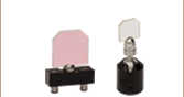
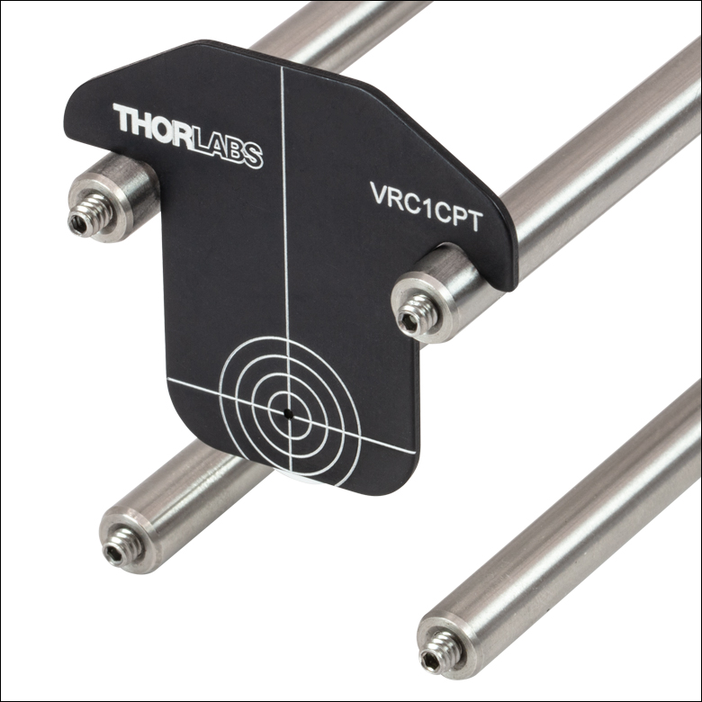
アライメントプレートVRC1CPTの背面にはアライメント用ターゲットが刻印されています。
- 吸収帯:250~540 nm
- チャージの必要なし
- ディスクの種類
- マウント無しタイプ
- SM外ネジ付きの筐体に納められたタイプ
- 30 mmケージ用のドロップイン式アライメントプレートに取り付けられたタイプ
こちらのアライメントディスクは、当社のレーザービュワーカードVRC1と同じ、蛍光の減衰時間の長い蛍光材料で作られており、UV域および可視域のビームのアライメントを容易にするように設計されています。Ø12.7 mm(Ø1/2インチ)またはØ25.4 mm(Ø1インチ)のマウント無しタイプ、SM外ネジ付き筐体に納められたタイプ、および30 mmケージシステム用のドロップイン式アライメントプレートに取り付けられたタイプの3種類をご用意しています。それぞれのアライメントディスクの特徴は下の表をご覧ください。
| Item # | Description | Alignment Features | Active Region | Absorption Band | Emission Band | Requires Charging |
|---|---|---|---|---|---|---|
| VRC1D05 | Ø1/2" Disk | Ø1.5 mm Hole in Disk Center | Ø1/2" (Ø12.7 mm) | 250 - 540 nm | 450 to 750 nm | No |
| VRC1D1 | Ø1" Disk | Ø1" (Ø25.4 mm) | ||||
| VRC1SM05 | Disk in Externally SM05-Threaded Housing | Target Guide Lines, Ø3 mm and Ø9 mm Concentric Circles (±0.22 mm Concentricity) | Ø0.40" (Ø10.2 mm) | |||
| VRC1SM1 | Disk in Externally SM1-Threaded Housing | Ø0.79" (Ø20 mm) | ||||
| VRC1SM2 | Disk in Externally SM2-Threaded Housing | Ø1.75" (Ø44.5 mm) | ||||
| VRC1CPT | Ø1/2" Disk on Drop-In Alignment Plate for 30 mm Cage Systems | 0.9 mm Hole in Plate Front: Ø1.5 mm Hole in Disk Center Back: Laser-Engraved Target with Ø4 mm, Ø7 mm, Ø10 mm, and Ø13 mm Concentric Circles | Ø1/2" (Ø12.7 mm) |
光用、アクリルキャスト材")
 ズーム
ズーム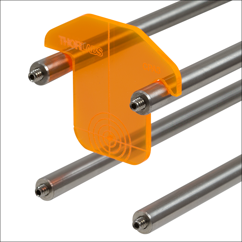
Click to Enlarge
30 mmケージシステム内のアライメントプレートCPA3
- オレンジ色アクリルキャスト材蛍光プレート、16 mm、 30 mm、 60 mmケージシステム用
- 対応するケージシステムの中央にアライメントするガイドラインならびにØ1 mmまたはØ5 mm貫通穴付き
- 蛍光イメージングシステム用ドロップイン式アライメントツール
こちらのドロップイン式アライメントプレートは、ケージベースの蛍光イメージングシステムの空間的校正ならびにアライメントに便利なツールです。アクリルキャスト材がオレンジ色の蛍光たんぱく質および蛍光色素と同様の蛍光スペクトルを生成します。これらのプレートは連続蛍光をもたらすため、視野調整、連続照明検証、サンプルのアライメントが実サンプルを使用する前に行うことができるため、蛍光試料に無駄に光を照射するのを避けることができます。
各プレートは厚さ1.7 mmのアクリルキャスト材を切断しています。またケージアセンブリの中心にはアライメントされたØ1 mmまたはØ5 mmの貫通穴があります。各貫通穴の周りには同心のアライメント用リングが刻印されています。製品は当社の16 mm、30 mm、60 mmケージシステム用にそれぞれご用意しております。25.4 mm x 50.8 mmまでのサイズ、色のカスタマイズについては当社までお問い合わせください。
| Item # | Color | Through Hole Diameter | Alignment Ring Diameters | Compatible Cage System | Thickness | Transmission (Click for Graph) | Requires Charging |
|---|---|---|---|---|---|---|---|
| SCPA2 | Orange | 1 mm (0.04") | 3 mm, 5 mm, 7 mm, and 9 mm | 16 mm | 1.7 mm ± 0.5 mm | No | |
| CPA3 | 1 mm (0.04") | 4 mm, 7 mm, 10 mm, and 13 mm | 30 mm | ||||
| CPA4 | 5 mm (0.20") | 7 mm, 10 mm, and 13 mm | 30 mm | ||||
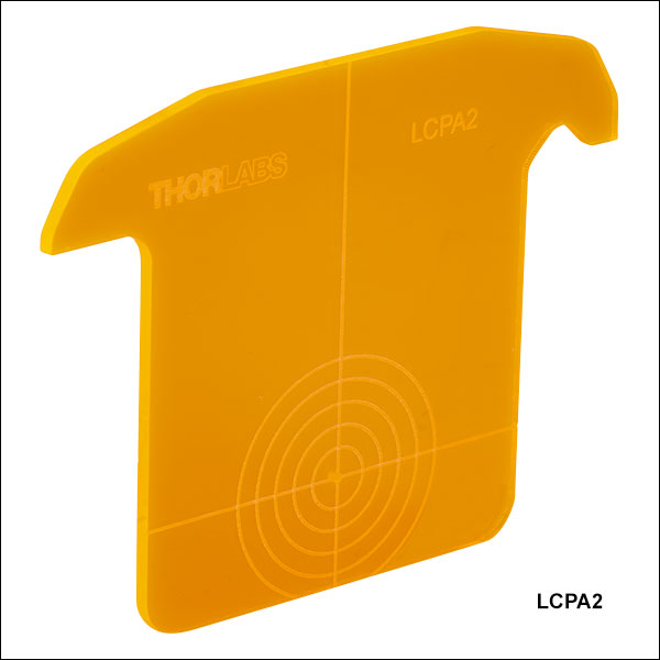
| LCPA2 | 1 mm (0.04") | 7 mm, 12 mm, 17 mm, 22 mm, and 27 mm | 60 mm |
光用、アクリルキャスト材")
 ズーム
ズーム
Click to Enlarge
生データ
10種類のディスクに当社のファイバ出力型LEDからの光を照射した時の蛍光スペクトル。これらの蛍光スペクトルを得るためのLEDについては生データをクリックしてご覧ください。 このデータは典型値で、性能は製造ロットにより異なる場合があります。
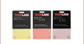
- 5色の蛍光アクリルディスク:青、緑、黄、オレンジ、赤
- 単体または5個入りセットでご提供
- Ø25.4 mm(Ø1インチ)、厚さ1.7 mm
- ターゲットガイドラインまたは中心穴付き
- 当社のØ25 mm~Ø25.4 mm(Ø1インチ)固定式レンズマウント、レンズチューブ、30 mmケージプレートに対応
こちらのディスクはワイドフィールド、共焦点、多光子顕微鏡イメージングシステムのアライメントにご使用いただけます。アクリルキャスト基板がもたらす蛍光スペクトルは、様々な蛍光色素のスペクトルに近似しているため、蛍光イメージングに使用される様々なレーザとの使用に適しています。こちらのディスクは連続蛍光をもたらすため、視野調整、連続照明検証、サンプルのアライメントが事前に評価でき、蛍光試料に無駄に光を照射するのを避けることができます。
各ディスクはアクリル製で、直径は25.4 mm、厚さは1.7 ± 0.5 mmです。各ディスクには、2つの同心円とターゲットラインの刻印か、Ø1.5 mmの中心穴が付いています。 25.4 mm x 50.8 mmまでサイズのカスタマイズについては当社までお問い合わせください。詳細については製品ページをご覧ください。
こちらのディスクは当社のØ25 mm~Ø25.4 mm(Ø1インチ)固定式マウントやレンズチューブまたは30 mmケージプレートに取り付け可能です。
| Item # | Color | Alignment Feature | Dimensions | Thickness | Transmission (Click for Graph) | Requires Charging |
|---|---|---|---|---|---|---|
| ADF1(-P5) | Blue | Target Guide Lines, Ø3.4 mm and Ø9.4 mm Concentric Circles | Ø1" (Ø25.4 mm), Unmounted | 1.7 mm ± 0.5 mm | Raw Data | No |
| ADF6 (-P5) | Ø1.5 mm ± 0.1 mm Hole in Disk Center | |||||
| ADF2(-P5) | Green | Target Guide Lines, Ø3.4 mm and Ø9.4 mm Concentric Circles | ||||
| ADF7(-P5) | Ø1.5 mm ± 0.1 mm Hole in Disk Center | |||||
| ADF3(-P5) | Yellow | Target Guide Lines, Ø3.4 mm and Ø9.4 mm Concentric Circles | ||||
| ADF8(-P5) | Ø1.5 mm ± 0.1 mm Hole in Disk Center | |||||
| ADF4(-P5) | Orange | Target Guide Lines, Ø3.4 mm and Ø9.4 mm Concentric Circles | ||||
| ADF9(-P5) | Ø1.5 mm ± 0.1 mm Hole in Disk Center | |||||
| ADF5(-P5) | Red | Target Guide Lines, Ø3.4 mm and Ø9.4 mm Concentric Circles | ||||
| ADF10(-P5) | Ø1.5 mm ± 0.1 mm Hole in Disk Center |
/赤外(IR)光用、難退色性蛍光材")
 ズーム
ズーム
Click to Enlarge
VRC2シリーズアライメントディスクの吸収帯と発光帯
 Click to Enlarge
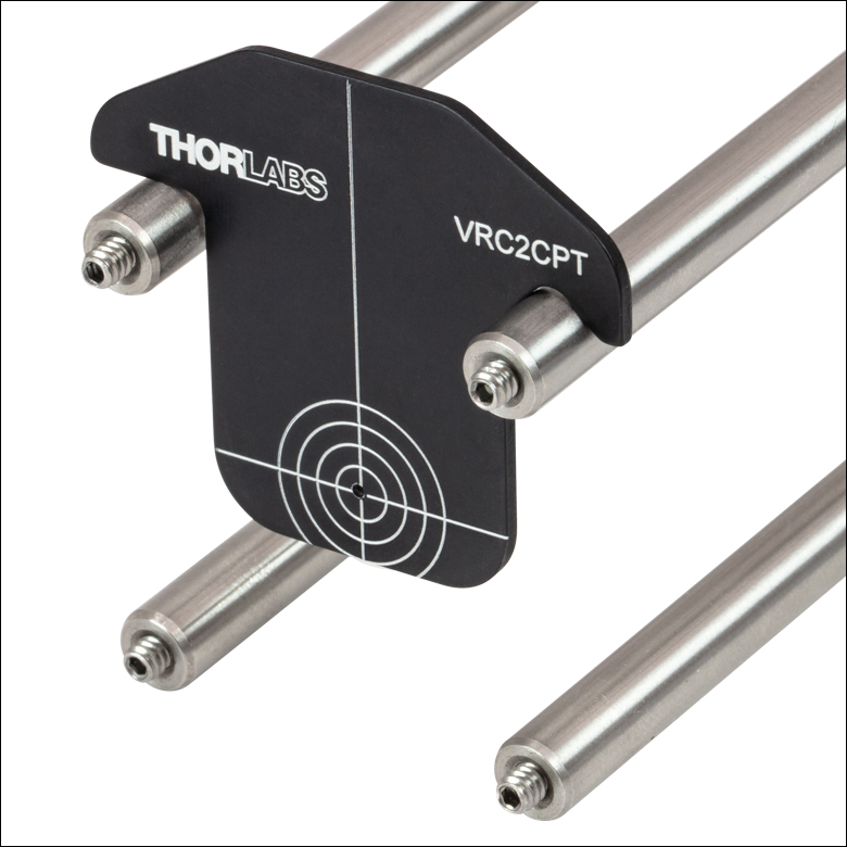
アライメントプレートVRC2CPTの背面にはアライメント用ターゲットが刻印されています。
- 吸収帯:400~640 nmおよび800~1700 nm
- 可視光によるチャージが必要
- ディスクの種類
- マウント無しタイプ
- RMS外ネジまたはSM外ネジの付いた筐体に納められたタイプ
- 30 mmケージ用のドロップイン式アライメントプレートに取り付けられたタイプ
こちらのアライメントディスクは、当社のレーザービュワーカードVRC2と同じ、蛍光の減衰時間の長い蛍光材料で作られており、可視(VIS)域および赤外(IR)域のビームのアライメントを容易にするように設計されています。Ø12.7 mm(Ø1/2インチ)またはØ25.4 mm(Ø1インチ)のマウント無しタイプ、RMS外ネジまたはSM外ネジの付いた筐体に納められたタイプ、および30 mmケージシステム用のドロップイン式アライメントプレートに取り付けられたタイプの3種類をご用意しています。それぞれのアライメントディスクの特徴は下の表をご覧ください。
| Item # | Description | Alignment Features | Active Region | Absorption Bands | Emission Band | Requires Charging |
|---|---|---|---|---|---|---|
| VRC2D05 | Ø1/2" Disk | Ø1.5 mm Hole in Disk Center | Ø1/2" (Ø12.7 mm) | 400 - 640 nm, 800 - 1700 nm | ~580 to 750 nm | Yes |
| VRC2D1 | Ø1" Disk | Ø1" (Ø25.4 mm) | ||||
| VRC2SM05 | Disk in Externally SM05-Threaded Housing | Target Guide Lines, Ø3 mm and Ø9 mm Concentric Circles (±0.22 mm Concentricity) | Ø0.40" (Ø10.2 mm) | |||
| VRC2RMS | Disk in Externally RMS-Threaded Housing | Ø0.7" (Ø18 mm) | ||||
| VRC2SM1 | Disk in Externally SM1-Threaded Housing | Ø0.79" (Ø20 mm) | ||||
| VRC2SM2 | Disk in Externally SM2-Threaded Housing | Ø1.75" (Ø44.5 mm) | ||||
| VRC2CPT | Ø1/2" Disk on Drop-In Alignment Plate for 30 mm Cage System | 0.9 mm Hole in Plate Front: Ø1.5 mm Hole in Disk Center Back: Laser Engraved Target with Ø4 mm, Ø7 mm, Ø10 mm, and Ø13 mm Concentric Circles | Ø1/2" (Ø12.7 mm) |
光用、難退色性蛍光材")
 ズーム
ズーム
Click to Enlarge
VRC4シリーズアライメントディスクの吸収帯と発光帯
 Click to Enlarge
アライメントプレートVRC4CPTの背面にはアライメントターゲットが刻印されています。
- 吸収帯:790~840 nm、870~1070 nm、および1500~1590 nm
- チャージの必要なし
- ディスクの種類
- マウント無しタイプ
- SM外ネジ付きの筐体に納められたタイプ
- 30 mmケージ用のドロップイン式アライメントプレートに取り付けられたタイプ
こちらのアライメントディスクは、当社のレーザービュワーカードVRC4と同じ、蛍光の減衰時間の長い蛍光材料で作られており、赤外(IR)域ビームのアライメントを容易にするように設計されています。Ø12.7 mm(Ø1/2インチ)またはØ25.4 mm(Ø1インチ)のマウント無しタイプ、SM外ネジ付き筐体に納められたタイプ、30 mmケージシステム用のドロップイン式アライメントプレートに取り付けられたタイプの3種類をご用意しています。それぞれのアライメントディスクの特徴は下の表をご覧ください。
| Item # | Description | Alignment Features | Active Region | Absorption Band | Emission Band | Requires Charging |
|---|---|---|---|---|---|---|
| VRC4D05 | Ø1/2" Disk | Ø1.5 mm Hole in Disk Center | Ø1/2" (Ø12.7 mm) | 790 - 840 nm, 870 - 1070 nm, 1500 - 1590 nm | ~520 to 580 nm | No |
| VRC4D1 | Ø1" Disk | Ø1" (Ø25.4 mm) | ||||
| VRC4SM05 | Disk in Externally SM05-Threaded Housing | Target Guide Lines, Ø3 mm and Ø9 mm Concentric Circles (±0.22 mm Concentricity) | Ø0.40" (Ø10.2 mm) | |||
| VRC4SM1 | Disk in Externally SM1-Threaded Housing | Ø0.79" (Ø20 mm) | ||||
| VRC4SM2 | Disk in Externally SM2-Threaded Housing | Ø1.75" (Ø44.5 mm) | ||||
| VRC4CPT | Ø1/2" Disk on Drop-In Alignment Plate for 30 mm Cage System | 0.9 mm Hole in Plate Front: Ø1.5 mm Hole in Disk Center Back: Laser Engraved Target with Ø4 mm, Ø7 mm, Ø10 mm, and Ø13 mm Concentric Circles | Ø1/2" (Ø12.7 mm) |
光用")
 ズーム
ズーム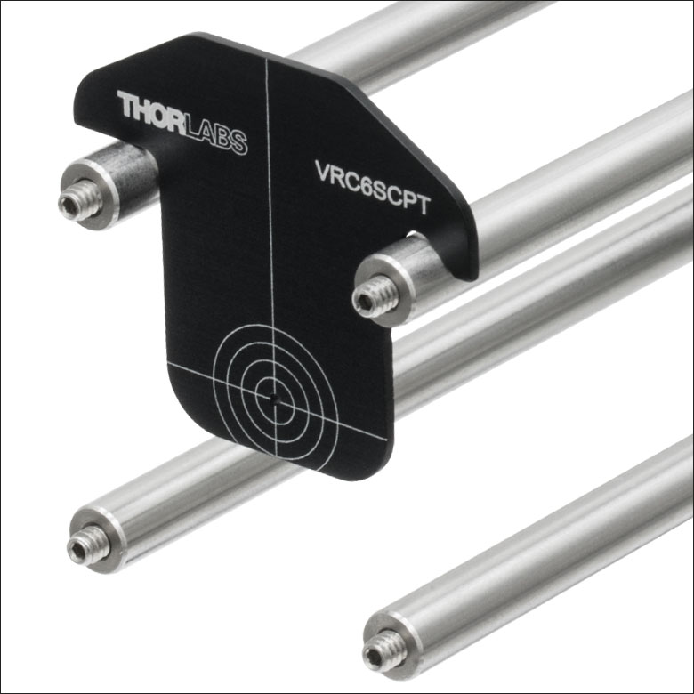
Click to Enlarge
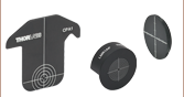
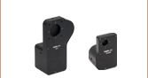
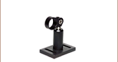
30 mmケージシステムに取り付けられたVRC6SCPTの背面
- 中赤外光に曝されると色が変わる液晶フィルム
- チャージの必要なし
- 最小検出パワー密度:0.05 W/mm2 @ 1550 nm(22 °C)
- 動作周囲温度:20~24 °C
- 最大の感度および可視性を得られる周囲温度:22 °C
- 当社の30 mmケージ部品またはSM1レンズチューブシステムと一緒にお使いください
Click to Enlarge
アライメントディスクVRC6SM1およびVRC6SCPTの感光部は23° C以上になると色が変わります。
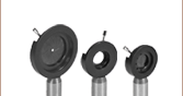
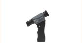
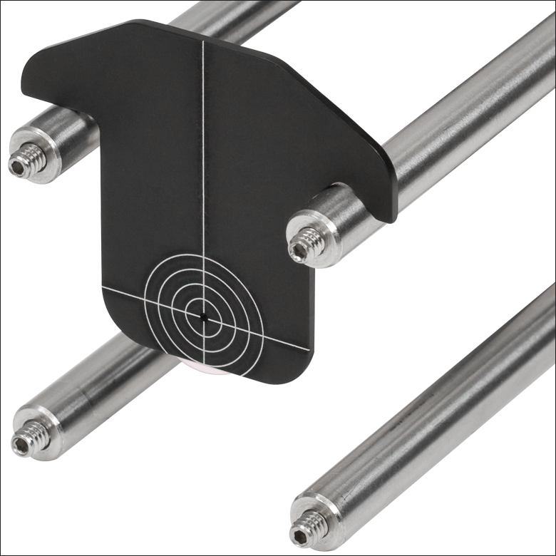
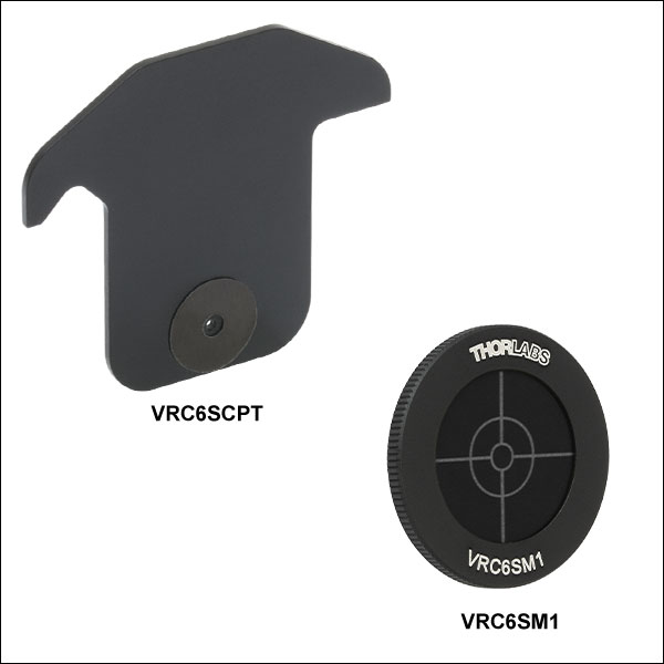
ケージプレート取付型中赤外光用アライメントディスクVRC6SCPTおよびSM1ネジ付き中赤外光用アライメントディスクVRC6SM1は、当社のディテクターカードVRC6Sと同じ熱変色性液晶(TLC)で作られており、1.5 µm~13.2 µmの波長範囲のレーザ光源でテストされています。
VRC6SCPTは、アライメントディスクがアルマイト加工アルミニウム製のケージアライメント用プレートに貼りつけてあり、ディスク中心のØ2.0 mmの穴とプレートのØ0.9 mmの貫通穴は一致しており、さらにそれらは30 mmケージシステムの中心ともぴったり合うよう配置されています。プレートの背面にはアライメントターゲットがレーザ刻印されており、直径Ø4 mm、Ø7 mm、Ø10 mm、Ø13 mmの同心円が描かれています(右の写真参照)。
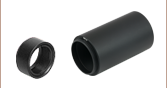
VRC6SM1はアライメントディスクがSM1ネジ付き筐体内部に納められた構成になっており、SM1レンズチューブシステムと一緒に使用すると中赤外光のアライメントが容易にできます。SM1外ネジのネジ深さは2.3 mmです。ディスクVRC6SM1のØ20 mmの感光部には、Ø3 mmならびにØ9 mmの同心円のターゲットガイドラインが刻印されています(左の写真参照)。
推奨する周辺温度は20~24 °Cですが、最大の感度および応答性が得られる周辺温度は22 °Cとなっています。約23 °C以下では検出部の色は黒色です。この温度を超えると、赤、黄色、緑の順に色が変わり、約28 °Cに達すると青色か紫色に変化します(左の写真参照)。このような色の変化は、レーザ照射または周囲温度の上昇によって起こります。周囲温度が20 °C以下の状態で使用すると、レーザに照射された液晶の温度が23 °C以上になるまでに時間がかかるため、応答性は低下します。これに対し24 °C以上で使用すると、感光部内のレーザに照射された領域とそれ以外の部分の色のコントラストが低くなるため感度が低下します。
レーザ照射後のアライメントディスクVRCS6M1を復元させるには、感光部にエアを噴射してください。ケージプレート取付型アライメントディスクVRC6SCPTの感光部は、表面を下に向けて数分間テーブルに置いておくことで復元します。ハイパワーのレーザを照射した後は、ディスクの復元に時間がかかったり、室温では色が元に戻らなかったりする場合があります。その場合は、0~ 4 °Cの冷蔵庫に数分間入れておくと復元が早まります。
注:ディスクのスポットサイズはパワー密度によって異なります。詳細についてはレーザ用ビュワーカードをご覧ください。
| Item # | Absorption Band | Minimum Detectable Power Density | Active Region | Alignment Feature | Requires Charging |
|---|---|---|---|---|---|
| VRC6SM1 | 1.5 to >13.2 µm | 0.05 mW/mm2 @ 1550 nm (22 °C) | Ø0.79" (Ø20.0 mm) | Target Guide Lines, Ø3 mm and Ø9 mm Concentric Circles, (±0.3 mm Concentricity) | No |
| VRC6SCPT | Ø0.39" (Ø10.0 mm) | Ø0.9 mm Hole in Plate Ø2.0 mm Hole in Disk Center |