小径ビーム走査型ガルバノミラーシステム
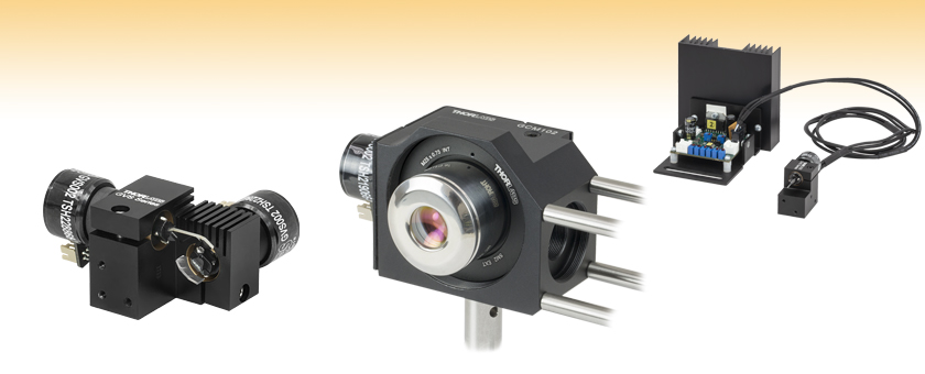
- For Small (<5 mm) Beam Diameters
- Single- and Dual-Axis Options with Choice of Mirror Coating
- Mounting Adapters for Easy Integration into Standard Thorlabs Optomechanics
GVS002
Dual-Axis Motor/Mirror Assembly with Silver Mirrors
GVS001
Galvo Scanning System
Mounting Adapters are Available that Allow Our Single- and Dual-Axis Galvo Mirror Systems to be Integrated with Thorlabs' Standard Optomechanics

Please Wait
| Key Specificationsa | ||||
|---|---|---|---|---|
| Max Beam Diameter | 5 mm | |||
| 2-Axis System Beam Offset | 10 mm | |||
| Wavelength Range (Ravg > 95%) | GVS00x (Silver): 500 nm - 2.0 µm GVS10x (Gold): 800 nm - 20.0 µm GVS20x (-E02): 400 nm - 750 nm | |||
| Repeatability | 15 μrad | |||
| Damage Threshold GVS00x (Silver) GVS10x (Gold) GVS20x (-E02) | 3 J/cm2 at 1064 nm, 10 ns pulse 2 J/cm2 at 1064 nm, 10 ns pulse 0.25 J/cm2 at 532 nm, 10 ns pulse | |||
| Linearity | 99.9% | |||
| Max Scan Angleb (Mechanical Angle) | ±12.5° (w/ 0.8 V/deg scaling) | |||
| Resolution (Mechanical) | With GPS011-xx Linear PSU: 0.0008° (15 µrad) With Standard Switch Mode PSU: 0.004° (70 µrad) | |||
| Full Scale Bandwidth | DC to 100 Hz Square wave, DC to 250 Hz Sine wave, DC to 175 Hz Triangular Wave, DC to 175 Hz Sawtooth | |||
| Small Angle (±0.2°) Bandwidth | DC to 1 kHz | |||
| Small Angle Step Responsec | 300 µs | |||
| Optical Position Sensor Output | 40 to 80 µA | |||
| Power Supply Requirements | ±15 to ±18 VDC | |||
特長
- 1軸および2軸システム
- 可動マグネットモータ設計により高速応答が可能
- 高精度光学ミラー位置検出
- 電流ダンピングとエラーリミッタ付きアナログPD制御回路
- ミラーコーティングの選択:
- 保護膜付き銀:500 nm~2.0 µm
- 保護膜付き金:800 nm~20.0 µm
- 広帯域誘電体:400 nm~750 nm
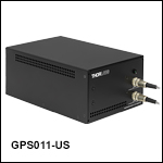
- 電源、ケーブル、ドライバーボード用カバーを含むキットもご用意
- ポストや30 mm ケージシステムに対応する取付け用アダプタ
- あおり調整プラットフォーム用アダプタでPY003/Mに取付け
高速走査型ガルバノミラー位置決めシステムは、ビーム径が<5 mmのOEMやカスタム仕様のレーザービームステアリングシステムに組み込むために設計されています。 各システムには1軸または2軸ガルバノモータおよびミラーアセンブリ、関連ドライバーボード、ドライバーボードヒートシンクが含まれています。 低ノイズのリニア電源(GPS011から始まる型番)やモータ/ ミラーアセンブリーヒートシンク(GHS003)も個別にお買い求めいただけます。また、本システムを駆動するためには、ファンクションジェネレータやDAQカードなどの アナログ信号用電源が別途必要です。詳細についてはマニュアルのChapter 3と4をご覧ください。
各ガルバノシステムにはモータ駆動用ケーブルが付属しており、それでドライバーボードとモータを接続します。この長さ1 mのケーブルは、ドライバーボードとモータの内部センサの両方に対して特別に校正されています。お手持ちのケーブルを取り付けて校正することはお勧めしません。カスタム仕様のガルバノシステムをご希望の場合は当社までご連絡ください。
1軸および2軸のガルバノシステムを光学系に容易に組み込めるように、様々な取付けアダプタを取り揃えています。ご用意しているアダプタには、1軸ガルバノミラー用30 mmケージマウント、2軸ガルバノシステム用ポスト&ケージ対応マウント、1軸および2軸ガルバノシステムにお使いいただけるあおり調整プラットフォーム用アダプタPY003などがございます。また、ガルバノのドライバーボード用カバーも別途ご用意しています。
ガルバノモータ/ミラーアセンブリ
当社のガルバノシステムは、シャフト上に光学ミラーが取り付けられたガルバノベースの走査型モータと制御ボードに位置フィードバックを送るディテクタで構成されています。GVSシリーズでは、静止型マグネットや回転式コイル設計ではなく可動マグネット設計を採用し、最速の応答時間と最高の共振周波数をご提供できます。 ミラー位置は、モータ筐体内にある光学センシングシステムを使ってエンコードされます。
回転シャフトの角加速度が大きいので、ミラーのサイズや形状、慣性モーメントは高性能ガルバノシステム設計において重要な要素となります。 また、加速度が大きくなってもミラーは平面性を維持する必要があります。 ガルバノモータの特性に合わせてシステムの性能を最大限に高めるために、当社のガルバノシステムでは、これらの要素は全て最適化されています。
ミラーは銀、金、または広帯域コーティングを標準在庫しております。
走査型ガルバノミラーアセンブリおよびドライバーボード
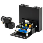
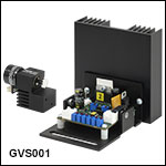
当社の走査型ガルバノミラーシステム全製品には、取付け済み1軸または2軸ミラー/モーターアセンブリとドライバーボードが付いています。右図は1軸ガルバノミラーGVS001とヒートシンク付きドライバーボードです。 ミラーアセンブリには、ミラーやモータ用の複数の取付穴や回転式カラーマウントが付いています。 小径5 mmのガルバノミラーにはミラーアセンブリのプラグ式コネクタが付属しています。他の取付けオプションやアクセサリについては下記をご参照ください。
サーボドライバーボード(全システム)
比例微分(PD)サーボドライバ回路は、モータ内にある光学位置検出システムからの信号を読み取り、ミラーを所望の位置に回転させるために必要なドライバ電圧を供給します。スキャナはベクトル位置決め(レーザーマーキング等)、ラスタ位置決め(プリンタや走査型レーザ顕微鏡)や、ステップ制御用途に適した Class 0のNon-Integratingサーボモータを使用しています。 また、PDコントローラによって優れた動的性能を備えています。 回路には高い加速度でも安定性を維持できる電流モジュールが付いています。なお、当社のガルバノシステムでは、全て同じドライバーボードが使用されています。
システムの操作
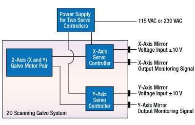
サーボドライバはDC電源、ガルバノモータ、入力電圧源に接続する必要があります(モニタ接続はオプションです)。連続走査用途については、ガルバノミラーを全ての範囲で走査するには、矩形波または正弦波出力のファンクションジェネレータで十分です。 さらに複雑なパターンを走査するには、DAQカードなどのプログラム可能な電圧源をご使用いただけます。なお、これらのシステムにはファンクションジェネレータやDAQカードは付属しておりませんのでご注意ください。入力電圧とミラーの位置の間の比率は 0.5、0.8、1 に切り替えることができます。これらのシステムでは、その比を0.8に設定した時、±10 Vの入力電圧に対して最大走査角度である±12.5°回転させることができます。 制御回路は、ミラーの位置のトラッキングに必要なモニタ出力も提供します。 また、駆動電流に比例した電圧もモータに供給され、コマンド位置と実際のミラー位置の差も制御回路によって提供されます。
閉ループミラー位置決め
ミラーの角度方向(位置)は、ガルバノメータ筐体内部に組み込まれた光電セルアレイおよび光源を使用して、光学的にエンコード化されています。各ミラーの向きは、フォトダイオードからの信号の比に対応しており、ガルバノミラーシステムの閉ループ制御が可能です。
このシステムは、 矩形波制御入力電圧を使う場合は100 Hzの周波数で、正弦波制御入力電圧を使う場合は250 Hzの周波数で、±12.5°フルメカニカルレンジの走査が可能です。0.2° の小角度単一ステップでは、ミラーは300 μsでコマンド指定した位置に達して止まります。最大スキャン周波数は1 kHzで、角度分解能は0.0008°(15 μrad)です。
ガルバノスキャナーシステムの仕様
| Item # | GVS001 and GVS002 | GVS101 and GVS102 | GVS201 and GVS202 | |
|---|---|---|---|---|
| Mirror | ||||
| Maximum Beam Diameter | 5 mm | |||
| 2-Axis System Beam Offset | 10 mm | |||
| Material | Quartz | |||
| Coating | Protected Silver | Protected Gold | Broadband Dielectric (-E02) | |
| Wavelength Range | 500 nm to 2.0 µm | 800 nm to 20.0 µm | 400 nm to 750 nm | |
| Damage Thresholda | 3.0 J/cm2 | 2.0 J/cm2 | 0.25 J/cm2 | |
| Parallelism | < 3 arcmin | |||
| Surface Quality | 40-20 Scratch-Dig | |||
| Front Surface Flatness (@633 nm) | λ | |||
| Clear Aperture | > 90% of Dimension | |||
| Motor and Position Sensor | ||||
| Linearity | 99.9% | |||
| Scale Drift | 40 ppm/°C (Max) | |||
| Zero Drift | 10 μrad/°C (Max) | |||
| Repeatability | 15 μrad | |||
| Resolution (Mechanical) | With GPS011-xx Linear PSU: 0.0008° (15 µrad) With Standard Switch Mode PSU: 0.004° (70 µrad) | |||
| Average Current | 1 A | |||
| Peak Current | 5 A | |||
| Maximum Scan Angleb (Mechanical Angle) | ±12.5° (Input Scale Factor 0.8 V per degree) | |||
| Motor Weight (With Cables, Without Brackets) | 50 g | |||
| Operating Temperature Range | 0 to 40 °C | |||
| Optical Position Sensor Output Range | 40 to 80 µA | |||
| Drive Electronics | ||||
| Full Scale Bandwidth | DC to 100 Hz Square Wave, DC to 250 Hz Sine Wave, DC to 175 Hz Triangular Wave, DC to 175 Hz Sawtooth | |||
| Small Angle (±0.2°) Bandwidth | DC to 1 kHz | |||
| Small Angle Step Responsec | 300 µs | |||
| Power Supply | ±15 to ±18 VDC (1.25 A rms, 5 A peak Max) | |||
| Analog Signal Input Resistance | 20 kΩ ± 1% (Differential Input) | |||
| Position Signal Output Resistance | 1 kΩ ± 1% | |||
| Analog Position Signal Input Range | ±10 V | |||
| Mechanical Position Signal Input Scale Factor | Switchable: 1.0 V, 0.8 V or 0.5 V per degree | |||
| Mechanical Position Signal Output Scale Factor | 0.5 V per degree | |||
| Operating Temperature Range | 0 to 40 °C | |||
| Servo Board Size (W x D x H) | 85 mm x 74 mm x 44 mm (3.35" x 2.9" x 1.73") | |||
Maximum Recommended Mechanical Scan Angles
| Item # | GVS001, GVS101 and GVS201 | GVS002, GVS102 and GVS202 | |
|---|---|---|---|
| Input Beam Diameter | X or Y Axis | X Axis | Y Axis |
| 5 mm | +10° / -12.5° | ±8° | +12.5° / -3° |
| 4 mm | ±12.5° | ±8.5° | ±12.5° |
| 3 mm | ±12.5° | +9.5° / -10° | ±12.5° |
| 2 mm | ±12.5° | +10° / -11.5° | ±12.5° |
| 1 mm | ±12.5° | +11° / -12.5° | ±12.5° |
電源の仕様
| Item # | GPS011-US | GPS011-EC | GPS011-JP |
|---|---|---|---|
| Input Voltage | 115 VAC, 60 Hz | 230 VAC, 50 Hz | 100 VAC, 50/60 Hz |
| Output Voltage | ±15 VDC, 3.0 A / 0.1 A, 1.4/6.3 ms | ||
| Fuses | T2.0 A Anti-Surge Ceramic | T1.0 A Anti-Surge Ceramic | T2.5 A Anti-Surge Ceramic |
| Dimensions | 179 mm x 274 mm (Max) x 122 mm (7.05" x 10.79" (Max) x 4.8") | ||
| Weight | 4.73 kg (10.4 lbs) | ||
このシステムの設定および操作にお使いいただけるのは、付属のケーブルのみです。ケーブルは延長しないでください。ドライバーボードとモータは付属のケーブルを使用して校正されています。別のケーブルを使用すると、システムの性能に影響を与えます。より長いケーブルを特注でご提供することは可能ですが、ご注文の際にそのご指定がない場合にはユニットを再校正する必要があります。詳細は当社までお問い合わせください。
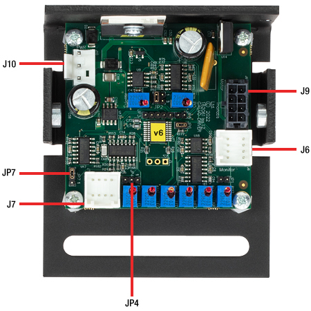
GVSシリーズドライバの接続部
Click to Enlarge
PCBコネクタの全体図。 各コネクタの詳細は下でご覧いただけます。
J10:電源用コネクタ
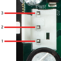
| Pin | Designation |
|---|---|
| 1 | + 15 V |
| 2 | Ground |
| 3 | - 15 V |
J6:診断用コネクタ
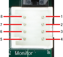
| Pin | Designation |
|---|---|
| 1 | Scanner Position |
| 2 | Internal Command Signal |
| 3 | Positioning Error x 5 |
| 4 | Motor Drive Current |
| 5 | Not Connected |
| 6 | Test Input (NC) |
| 7 | Motor + Coil Voltage / 2 |
| 8 | Ground |
J9:モータ用コネクタ
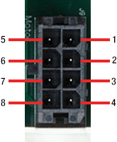
| Pin | Designation |
|---|---|
| 1 | Position Sensor A Current |
| 2 | Position Sensor Ground |
| 3 | Position Sensor Cable Shield |
| 4 | Drive Cable Shield |
| 5 | Position Sensor B Current |
| 6 | Position Sensor Power |
| 7 | Motor + Coil |
| 8 | Motor - Coil |
ガルバノアセンブリモータ用コネクタ
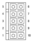
| Pin | Designation |
|---|---|
| 1 | Motor + Coil (Power Shield Floating) |
| 2 | Motor - Coil (Power Shield Floating) |
| 3 | Not Used |
| 4 | Not Used |
| 5 | Position Sensor B Current |
| 6 | Position Sensor Ground |
| 7 | Position Sensor A Current |
| 8 | Position Sensor Power (Automated Gain Control) |
| 9 | Position Sensor Cable Shield |
| 10 | Not Used |
J7:コマンド入力用コネクタ
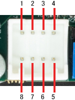
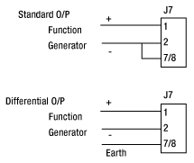
| Pin | Designation |
|---|---|
| 1 | Command Input +ve |
| 2 | Command Input -ve |
| 3 | DRV OK |
| 4 | External Enable |
| 5 | -12 V Output (Low Impedance O/P) |
| 6 | +12 V Output (Low Impedance O/P) |
| 7 | Ground |
| 8 | Ground |
JP7:電圧/角度の変換係数調整
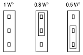
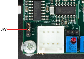
最大スキャン角度を±12.5°にするときは、変換係数が0.8 V/°になるようにジャンパをセットします(上の図を参照)。同様に、小さな入力信号でフルスキャン角度に到達することができるように、変換係数を0.5 V/°に設定することもできます。この場合は、入力電圧を最大±6.25 Vまでに制限してください。
ドライバーボードの外部からのENABLE化
JP4のピン2と3にジャンパをセットすることで、ドライブ回路を外部からENABL化できるようになります。

JP4
そうしておくと、J7のピン4に5 V CMOS信号を送信することでドライブ回路のENABLE/DISABLEを制御できます。
J7のピン4でロジック・ハイの信号を受信するか、または何も信号が無い場合は、ドライブ回路はENABLEになります。一方、ロジック・ローの信号を受信すると、ドライブ回路はDISABLEになります。
| Pin | Designation |
|---|---|
| 1 | Command Input +ve |
| 2 | Command Input -ve |
| 3 | No Connect |
| 4 | External Enable |
| 5 | -12 V Output |
| 6 | +12 V Output |
| 7 | Ground |
| 8 | Ground |

J7
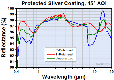
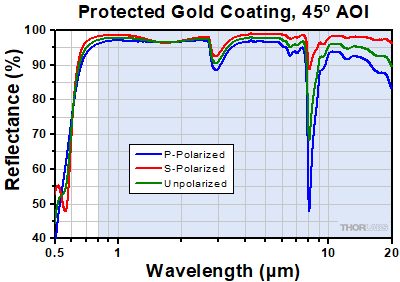
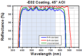
下の曲線は、ガルバノシステムGVSシリーズに付属するコーティング付きミラーの反射率データです。網掛けの部分は、各コーティングの推奨使用範囲 を示しています。この帯域外(特に反射率が上下したり傾斜したりしている範囲)での反射率は品質管理の面で厳密にモニタされたものではなく、ロット毎にも バラツキがある可能性がありますのでご注意ください。
| Damage Threshold Specifications | |
|---|---|
| Item # Prefix | Damage Threshold |
| GVS00- | 3 J/cm2 at 1064 nm, 10 ns |
| GVS10- | 2 J/cm2 at 1064 nm, 10 ns |
| GVS20- | 0.25 J/cm2 at 532 nm, 10 ns |
当社の小径ビーム走査型ガルバノミラーシステムの損傷閾値データ
右の仕様は、当社の小径ビーム走査型ガルバノミラーシステムの測定データです。損傷閾値の仕様は、型番の先頭にくる文字(GVSXX-)が同じであれば、ドライバの数や測定システムにかかわらず同じです。
レーザによる損傷閾値について
このチュートリアルでは、レーザ損傷閾値がどのように測定され、使用する用途に適切な光学素子の決定にその値をどのようにご利用いただけるかを総括しています。お客様のアプリケーションにおいて、光学素子を選択する際、光学素子のレーザによる損傷閾値(Laser Induced Damage Threshold :LIDT)を知ることが重要です。光学素子のLIDTはお客様が使用するレーザの種類に大きく依存します。連続(CW)レーザは、通常、吸収(コーティングまたは基板における)によって発生する熱によって損傷を引き起こします。一方、パルスレーザは熱的損傷が起こる前に、光学素子の格子構造から電子が引き剥がされることによって損傷を受けます。ここで示すガイドラインは、室温で新品の光学素子を前提としています(つまり、スクラッチ&ディグ仕様内、表面の汚染がないなど)。光学素子の表面に塵などの粒子が付くと、低い閾値で損傷を受ける可能性があります。そのため、光学素子の表面をきれいで埃のない状態に保つことをお勧めします。光学素子のクリーニングについては「光学素子クリーニングチュートリアル」をご参照ください。
テスト方法
当社のLIDTテストは、ISO/DIS 11254およびISO 21254に準拠しています。
初めに、低パワー/エネルギのビームを光学素子に入射します。その光学素子の10ヶ所に1回ずつ、設定した時間(CW)またはパルス数(決められたprf)、レーザを照射します。レーザを照射した後、倍率約100倍の顕微鏡を用いた検査で確認し、すべての確認できる損傷を調べます。特定のパワー/エネルギで損傷のあった場所の数を記録します。次に、そのパワー/エネルギを増やすか減らすかして、光学素子にさらに10ヶ所レーザを照射します。このプロセスを損傷が観測されるまで繰返します。損傷閾値は、光学素子が損傷に耐える、損傷が起こらない最大のパワー/エネルギになります。1つのミラーBB1-E02の試験結果は以下のようなヒストグラムになります。
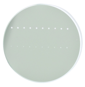
上の写真はアルミニウムをコーティングしたミラーでLIDTテストを終えたものです。このテストは、損傷を受ける前のレーザのエネルギは0.43 J/cm2 (1064 nm、10 ns pulse、 10 Hz、Ø1.000 mm)でした。
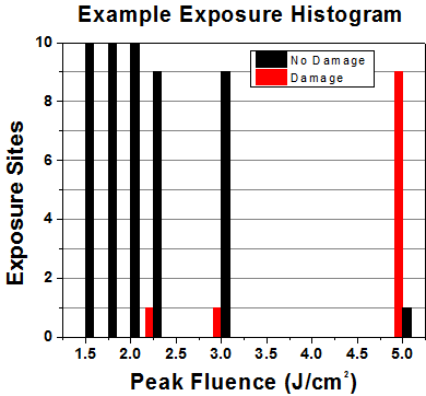
| Example Test Data | |||
|---|---|---|---|
| Fluence | # of Tested Locations | Locations with Damage | Locations Without Damage |
| 1.50 J/cm2 | 10 | 0 | 10 |
| 1.75 J/cm2 | 10 | 0 | 10 |
| 2.00 J/cm2 | 10 | 0 | 10 |
| 2.25 J/cm2 | 10 | 1 | 9 |
| 3.00 J/cm2 | 10 | 1 | 9 |
| 5.00 J/cm2 | 10 | 9 | 1 |
試験結果によれば、ミラーの損傷閾値は 2.00 J/cm2 (532 nm、10 ns pulse、10 Hz、 Ø0.803 mm)でした。尚、汚れや汚染によって光学素子の損傷閾値は大幅に低減されるため、こちらの試験はクリーンな光学素子で行っています。また、特定のロットのコーティングに対してのみ試験を行った結果ではありますが、当社の損傷閾値の仕様は様々な因子を考慮して、実測した値よりも低めに設定されており、全てのコーティングロットに対して適用されています。
CWレーザと長パルスレーザ
光学素子がCWレーザによって損傷を受けるのは、通常バルク材料がレーザのエネルギを吸収することによって引き起こされる溶解、あるいはAR(反射防止)コーティングのダメージによるものです[1]。1 µsを超える長いパルスレーザについてLIDTを論じる時は、CWレーザと同様に扱うことができます。
パルス長が1 nsと1 µs の間のときは、損傷は吸収、もしくは絶縁破壊のどちらかで発生していると考えることができます(CWとパルスのLIDT両方を調べなければなりません)。吸収は光学素子の固有特性によるものか、表面の不均一性によるものかのどちらかによって起こります。従って、LIDTは製造元の仕様以上の表面の質を有する光学素子にのみ有効です。多くの光学素子は、ハイパワーCWレーザで扱うことができる一方、アクロマティック複レンズのような接合レンズやNDフィルタのような高吸収光学素子は低いCWレーザ損傷閾値になる傾向にあります。このような低い損傷閾値は接着剤や金属コーティングにおける吸収や散乱によるものです。
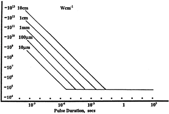
線形パワー密度におけるLIDTに対するパルス長とスポットサイズ。長パルス~CWでは線形パワー密度はスポットサイズにかかわらず一定です。 このグラフの出典は[1]です。
繰返し周波数(prf)の高いパルスレーザは、光学素子に熱的損傷も引き起こします。この場合は吸収や熱拡散率のような因子が深く関係しており、残念ながらprfの高いレーザが熱的影響によって光学素子に損傷を引き起こす場合の信頼性のあるLIDTを求める方法は確立されておりません。prfの大きいビームでは、平均出力およびピークパワーの両方を等しいCW出力と比較する必要があります。また、非常に透過率の高い材料では、prfが上昇してもLIDTの減少は皆無かそれに近くなります。
ある光学素子の固有のCWレーザの損傷閾値を使う場合には、以下のことを知る必要があります。
- レーザの波長
- ビーム径(1/e2)
- ビームのおおよその強度プロファイル(ガウシアン型など)
- レーザのパワー密度(トータルパワーをビームの強度が1/e2の範囲の面積で割ったもの)
ビームのパワー密度はW/cmの単位で計算します。この条件下では、出力密度はスポットサイズとは無関係になります。つまり、スポットサイズの変化に合わせてLIDTを計算し直す必要がありません(右グラフ参照)。平均線形パワー密度は、下の計算式で算出できます。

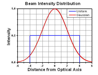
ここでは、ビーム強度プロファイルは一定であると仮定しています。次に、ビームがホットスポット、または他の不均一な強度プロファイルの場合を考慮して、おおよその最大パワー密度を計算する必要があります。ご参考までに、ガウシアンビームのときはビームの強度が1/e2の2倍のパワー密度を有します(右下図参照)。
次に、光学素子のLIDTの仕様の最大パワー密度を比較しましょう。損傷閾値の測定波長が光学素子に使用する波長と異なっている場合には、その損傷閾値は適宜補正が必要です。おおよその目安として参考にできるのは、損傷閾値は波長に対して比例関係であるということです。短い波長で使う場合、損傷閾値は低下します(つまり、1310 nmで10 W/cmのLIDTならば、655 nmでは5 W/cmと見積もります)。

この目安は一般的な傾向ですが、LIDTと波長の関係を定量的に示すものではありません。例えば、CW用途では、損傷はコーティングや基板の吸収によってより大きく変化し、必ずしも一般的な傾向通りとはなりません。上記の傾向はLIDT値の目安として参考にしていただけますが、LIDTの仕様波長と異なる場合には当社までお問い合わせください。パワー密度が光学素子の補正済みLIDTよりも小さい場合、この光学素子は目的の用途にご使用いただけます。
当社のウェブ上の損傷閾値の仕様と我々が行った実際の実験の値の間にはある程度の差があります。これはロット間の違いによって発生する誤差を許容するためです。ご要求に応じて、当社は個別の情報やテスト結果の証明書を発行することもできます。損傷解析は、類似した光学素子を用いて行います(お客様の光学素子には損傷は与えません)。試験の費用や所要時間などの詳細は、当社までお問い合わせください。
パルスレーザ
先に述べたように、通常、パルスレーザはCWレーザとは異なるタイプの損傷を光学素子に引き起こします。パルスレーザは損傷を与えるほど光学素子を加熱しませんが、光学素子から電子をひきはがします。残念ながら、お客様のレーザに対して光学素子のLIDTの仕様を照らし合わせることは非常に困難です。パルスレーザのパルス幅に起因する光学素子の損傷には、複数の形態があります。以下の表中のハイライトされた列は当社の仕様のLIDT値が当てはまるパルス幅に対する概要です。
パルス幅が10-9 sより短いパルスについては、当社の仕様のLIDT値と比較することは困難です。この超短パルスでは、多光子アバランシェ電離などのさまざまなメカニクスが損傷機構の主流になります[2]。対照的に、パルス幅が10-7 sと10-4 sの間のパルスは絶縁破壊、または熱的影響により光学素子の損傷を引き起こすと考えられます。これは、光学素子がお客様の用途に適しているかどうかを決定するために、レーザービームに対してCWとパルス両方による損傷閾値を参照しなくてはならないということです。
| Pulse Duration | t < 10-9 s | 10-9 < t < 10-7 s | 10-7 < t < 10-4 s | t > 10-4 s |
|---|---|---|---|---|
| Damage Mechanism | Avalanche Ionization | Dielectric Breakdown | Dielectric Breakdown or Thermal | Thermal |
| Relevant Damage Specification | No Comparison (See Above) | Pulsed | Pulsed and CW | CW |
お客様のパルスレーザに対してLIDTを比較する際は、以下のことを確認いただくことが重要です。
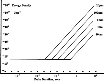
エネルギ密度におけるLIDTに対するパルス長&スポットサイズ。短パルスでは、エネルギ密度はスポットサイズにかかわらず一定です。このグラフの出典は[1]です。
- レーザの波長
- ビームのエネルギ密度(トータルエネルギをビームの強度が1/e2の範囲の面積で割ったもの)
- レーザのパルス幅
- パルスの繰返周波数(prf)
- 実際に使用するビーム径(1/e2 )
- ビームのおおよその強度プロファイル(ガウシアン型など)
ビームのエネルギ密度はJ/cm2の単位で計算します。右のグラフは、短パルス光源には、エネルギ密度が適した測定量であることを示しています。この条件下では、エネルギ密度はスポットサイズとは無関係になります。つまり、スポットサイズの変化に合わせてLIDTを計算し直す必要がありません。ここでは、ビーム強度プロファイルは一定であると仮定しています。ここで、ビームがホットスポット、または他の不均一な強度プロファイルの場合を考慮して、おおよその最大パワー密度を計算する必要があります。ご参考までに、ガウシアンビームのときは一般にビームの強度が1/e2のときの2倍のパワー密度を有します。
次に、光学素子のLIDTの仕様と最大エネルギ密度を比較しましょう。損傷閾値の測定波長が光学素子に使用する波長と異なっている場合には、その損傷閾値は適宜補正が必要です[3]。経験則から、損傷閾値は波長に対して以下のような平方根の関係であるということです。短い波長で使う場合、損傷閾値は低下します(例えば、1064 nmで 1 J/cm2のLIDTならば、532 nmでは0.7 J/cm2と計算されます)。

波長を補正したエネルギ密度を得ました。これを以下のステップで使用します。
ビーム径は損傷閾値を比較する時にも重要です。LIDTがJ/cm2の単位で表される場合、スポットサイズとは無関係になりますが、ビームサイズが大きい場合、LIDTの不一致を引き起こす原因でもある不具合が、より明らかになる傾向があります[4]。ここで示されているデータでは、LIDTの測定には<1 mmのビーム径が用いられています。ビーム径が5 mmよりも大きい場合、前述のようにビームのサイズが大きいほど不具合の影響が大きくなるため、LIDT (J/cm2)はビーム径とは無関係にはなりません。
次に、パルス幅について補正します。パルス幅が長くなるほど、より大きなエネルギに光学素子は耐えることができます。パルス幅が1~100 nsの場合の近似式は以下のようになります。

お客様のレーザのパルス幅をもとに、光学素子の補正されたLIDTを計算するのにこの計算式を使います。お客様の最大エネルギ密度が、この補正したエネルギ密度よりも小さい場合、その光学素子はお客様の用途でご使用いただけます。ご注意いただきたい点は、10-9 s と10-7 sの間のパルスにのみこの計算が使えることです。パルス幅が10-7 sと10-4 sの間の場合には、CWのLIDTも調べなければなりません。
当社のウェブ上の損傷閾値の仕様と我々が行った実際の実験の値の間にはある程度の差があります。これはロット間の違いによって発生する誤差を許容するためです。ご要求に応じて、当社では個別のテスト情報やテスト結果の証明書を発行することも可能です。詳細は、当社までお問い合わせください。
[1] R. M. Wood, Optics and Laser Tech. 29, 517 (1998).
[2] Roger M. Wood, Laser-Induced Damage of Optical Materials (Institute of Physics Publishing, Philadelphia, PA, 2003).
[3] C. W. Carr et al., Phys. Rev. Lett. 91, 127402 (2003).
[4] N. Bloembergen, Appl. Opt. 12, 661 (1973).
レーザーシステムが光学素子に損傷を引き起こすかどうか判断するプロセスを説明するために、レーザによって引き起こされる損傷閾値(LIDT)の計算例をいくつかご紹介します。同様の計算を実行したい場合には、右のボタンをクリックしてください。計算ができるスプレッドシートをダウンロードいただけます。ご使用の際には光学素子のLIDTの値と、レーザーシステムの関連パラメータを緑の枠内に入力してください。スプレッドシートでCWならびにパルスの線形パワー密度、ならびにパルスのエネルギ密度を計算できます。これらの値はスケーリング則に基づいて、光学素子のLIDTの調整スケール値を計算するのに用いられます。計算式はガウシアンビームのプロファイルを想定しているため、ほかのビーム形状(均一ビームなど)には補正係数を導入する必要があります。 LIDTのスケーリング則は経験則に基づいていますので、確度は保証されません。なお、光学素子やコーティングに吸収があると、スペクトル領域によってLIDTが著しく低くなる場合があります。LIDTはパルス幅が1ナノ秒(ns)未満の超短パルスには有効ではありません。
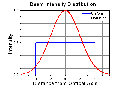
ガウシアンビームの最大強度は均一ビームの約2倍です。
CWレーザの例
波長1319 nm、ビーム径(1/e2)10 mm、パワー0.5 Wのガウシアンビームを生成するCWレーザーシステム想定します。このビームの平均線形パワー密度は、全パワーをビーム径で単純に割ると0.5 W/cmとなります。

しかし、ガウシアンビームの最大パワー密度は均一ビームの約2倍です(右のグラフ参照)。従って、システムのより正確な最大線形パワー密度は1 W/cmとなります。
アクロマティック複レンズAC127-030-CのCW LIDTは、1550 nmでテストされて350 W/cmとされています。CWの損傷閾値は通常レーザ光源の波長に直接スケーリングするため、LIDTの調整値は以下のように求められます。

LIDTの調整値は350 W/cm x (1319 nm / 1550 nm) = 298 W/cmと得られ、計算したレーザーシステムのパワー密度よりも大幅に高いため、この複レンズをこの用途に使用しても安全です。
ナノ秒パルスレーザの例:パルス幅が異なる場合のスケーリング
出力が繰返し周波数10 Hz、波長355 nm、エネルギ1 J、パルス幅2 ns、ビーム径(1/e2)1.9 cmのガウシアンビームであるNd:YAGパルスレーザーシステムを想定します。各パルスの平均エネルギ密度は、パルスエネルギをビームの断面積で割って求めます。

上で説明したように、ガウシアンビームの最大エネルギ密度は平均エネルギ密度の約2倍です。よって、このビームの最大エネルギ密度は約0.7 J/cm2です。
このビームのエネルギ密度を、広帯域誘電体ミラーBB1-E01のLIDT 1 J/cm2、そしてNd:YAGレーザーラインミラーNB1-K08のLIDT 3.5 J/cm2と比較します。LIDTの値は両方とも、波長355 nm、パルス幅10 ns、繰返し周波数10 Hzのレーザで計測しました。従って、より短いパルス幅に対する調整を行う必要があります。 1つ前のタブで説明したようにナノ秒パルスシステムのLIDTは、パルス幅の平方根にスケーリングします:

この調整係数により広帯域誘電体ミラーBB1-E01のLIDTは0.45 J/cm2に、Nd:YAGレーザーラインミラーのLIDTは1.6 J/cm2になり、これらをビームの最大エネルギ密度0.7 J/cm2と比較します。広帯域ミラーはレーザによって損傷を受ける可能性があり、より特化されたレーザーラインミラーがこのシステムには適していることが分かります。
ナノ秒パルスレーザの例:波長が異なる場合のスケーリング
波長1064 nm、繰返し周波数2.5 Hz、パルスエネルギ100 mJ、パルス幅10 ns、ビーム径(1/e2)16 mmのレーザ光を、NDフィルタで減衰させるようなパルスレーザーシステムを想定します。これらの数値からガウシアン出力における最大エネルギ密度は0.1 J/cm2になります。Ø25 mm、OD 1.0の反射型NDフィルタ NDUV10Aの損傷閾値は355 nm、10 nsのパルスにおいて0.05 J/cm2で、同様の吸収型フィルタ NE10Aの損傷閾値は532 nm、10 nsのパルスにおいて10 J/cm2です。1つ前のタブで説明したように光学素子のLIDTは、ナノ秒パルス領域では波長の平方根にスケーリングします。

スケーリングによりLIDTの調整値は反射型フィルタでは0.08 J/cm2、吸収型フィルタでは14 J/cm2となります。このケースでは吸収型フィルタが光学損傷を防ぐには適した選択肢となります。
マイクロ秒パルスレーザの例
パルス幅1 µs、パルスエネルギ150 µJ、繰返し周波数50 kHzで、結果的にデューティーサイクルが5%になるレーザーシステムについて考えてみます。このシステムはCWとパルスレーザの間の領域にあり、どちらのメカニズムでも光学素子に損傷を招く可能性があります。レーザーシステムの安全な動作のためにはCWとパルス両方のLIDTをレーザーシステムの特性と比較する必要があります。
この比較的長いパルス幅のレーザが、波長980 nm、ビーム径(1/e2)12.7 mmのガウシアンビームであった場合、線形パワー密度は5.9 W/cm、1パルスのエネルギ密度は1.2 x 10-4 J/cm2となります。これをポリマーゼロオーダ1/4波長板WPQ10E-980のLIDTと比較してみます。CW放射に対するLIDTは810 nmで5 W/cm、10 nsパルスのLIDTは810 nmで5 J/cm2です。前述同様、光学素子のCW LIDTはレーザ波長と線形にスケーリングするので、CWの調整値は980 nmで6 W/cmとなります。一方でパルスのLIDTはレーザ波長の平方根とパルス幅の平方根にスケーリングしますので、1 µsパルスの980 nmでの調整値は55 J/cm2です。光学素子のパルスのLIDTはパルスレーザのエネルギ密度よりはるかに大きいので、個々のパルスが波長板を損傷することはありません。しかしレーザの平均線形パワー密度が大きいため、高出力CWビームのように光学素子に熱的損傷を引き起こす可能性があります。
| Posted Comments: | |
成龙 姜
(posted 2024-10-19 03:46:45.44) 您好!在我的驱动系统中J6口的1号引脚在J71、2号引脚输入模拟信号后始终为0V,而在半个月之前还能正常使用,请问我应该如何解决这个问题?谢谢您。 zaixing wen
(posted 2024-10-10 16:53:14.087) 您好,我想利用您的GVS002振镜搭建一套中心波段840nm,带宽40nm的OCT系统,请问扫描部分还需要一些什么配件 spolineni
(posted 2024-10-17 09:59:54.0) Thank you for reaching out! I’ll contact you personally to discuss your OCT system requirements with the GVS002 galvanometer and recommend the necessary accessories we can offer for the scanning setup. user
(posted 2024-08-22 21:38:05.18) I tend to use dual axis kit for free space communication. Does is suitable for that application? What software is used for simulation? dnewnham
(posted 2024-09-02 03:38:55.0) Thank you for your inquiry. These parts do not have an associated software and are instead designed to be used in conjunction with a DAQ card or signal generator that you will have to provide yourself which will include the software you need. Some recommendations for DAQ cards include: NI USB-6211, NI USB-6003, or NI USB-6008. I will reach out to discuss your application and the suitability of these device further with you. Huabing Tan
(posted 2024-07-23 01:27:45.987) 您好!我们采购了贵司一套GVS002 - 二维振镜系统,我们在使用的过程中发现两个问题,想确认下这两个问题。问题1:我们在实验中发现,由函数发生器DAQ卡来操作伺服驱动器时,函数发生器DAQ卡生成驱动信号到振镜接收到信号到达指定位置有延迟现象,而且延迟的时间与固有的电气回路长度和驱动信号有关。关于问题1,我想知道的是振镜的延迟跟什么因素有关,这个延迟的时间怎么通过理论计算出来?问题2:我们将二维振镜的X轴和Y轴的振镜扫描位置反馈信号(J6诊断接头的引脚1和8)接出到示波器看振镜实际扫描位置;振镜X轴快轴驱动信号为三角波信号,振镜Y轴慢轴驱动信号为阶梯信号;在样的驱动信号下我们发现,当振镜Y轴慢轴固定不动,振镜X轴快轴做横向扫描,从左往右扫描到最右侧再往回(从右往左)时在拐点附近Y轴的振镜扫描位置反馈信号会有波动(但此时Y轴的驱动信号一直是个定值,Y轴慢轴固定不动),振镜X轴和Y轴分别有对应的驱动板,按道理Y轴的振镜扫描位置反馈信号不会受振镜X轴的影响,请问Y轴的振镜扫描位置反馈信号出现波动的原因是什么?是否可以避免出现这一波动?以上就是我的两个问题,期待回复!谢谢! Daniel Kang
(posted 2024-06-17 12:32:53.587) I am going to use GVS002.
In manual, servo driver needs 15V & 1.25 rms A ( peak 5A)
If galvo does low frequency less than 100Hz (sine) and low angle less than 2V, 15V and 3A of power supply is enogh to drive in stable? spolineni
(posted 2024-06-25 08:24:38.0) Thank you for your inquiry. To ensure optimal performance of your GVS002 servo driver across all sweeping angles, we recommend using a 15V power supply capable of providing 1.25 RMS A, peak of 5A. Please note that we have not specifically tested the system with 15V and 3A power supply. As a cautious measure, we advise following the recommended specifications for best results. Vítor Rodrigues
(posted 2024-01-12 08:52:26.54) Greetings! We are currently utilizing the GVS002 and, as of now, we would like to devise an external controller which, among other things, would further compensate the oscillatory transient response of the device (as the internal PD controller is not sufficient for our application), but a few parameters weren't provided.
Does someone have any (or all) of the following parameters?
- Torque Constant for the rotor
- Counter EMF constant (if different from Torque Constant)
- Viscous friction coefficient for the rotor
- Spring constant for the control spring/suspension spolineni
(posted 2024-01-18 01:45:13.0) Hello Vítor, Thank you for your enquiry. I will reach out to you directly to assist you further. Marzanna Sz
(posted 2023-05-31 13:20:21.957) Hi,
I am using small beam diameter galvo system kit. In description, you stated to provide all necessary cables. I got cables connecting galvo mirrors with the power supplies, but I cannot find cables to connect driver cards with PCI card. Are you providing it too in the kit because mine is missing ?
Regards,
Marzanna Conner Phillips
(posted 2023-05-25 12:48:29.223) Greetings,
We are looking at the GVS002 for OCT applications. The GCM102 looks nice at first glance, but we would like to have a cage system after the output to enable use of a dichroic mirror and optical camera. Is there an easy way to couple a cage to the output of the GCM102 or would a GVS012/M with GCM012/M be more appropriate? fguzman
(posted 2023-06-22 06:47:48.0) Thanks for your enquiry. The difference with the GVS012 and GVS012/M, is that the first is the imperial version and the second is the metric version. So you would need this and the galvo to be the same versions, but apart from the dimensions and threads, there is no application difference. Regarding the use of the GCM102 you could use the CP38T (https://www.thorlabs.com/thorproduct.cfm?partnumber=CP38T). I will contact you directly to further discuss your application. Zhichao YANG
(posted 2023-04-13 21:33:21.16) I am using an original PSU and GVS002 system, which has been adjusted to 230V. When the motor is not connected, the PSU indicator light is green.
However, when the motor is connected, the indicator light does not turn on and the motor does not produce normal working sounds. How can I resolve this issue? How can I confirm if the motor is functioning properly? JReeder
(posted 2023-04-17 03:33:50.0) Thank you for your enquiry. I will reach out to you directly to assist with troubleshooting the issue. Kibeom Park
(posted 2023-03-14 13:33:15.95) I am using the 1300nm OCT system. Could you make the
galvanometer coating with Dielectric (-E04)? JReeder
(posted 2023-03-20 07:25:54.0) Thank you for your enquiry. Our custom solutions team will reach out to you to discuss feasibility of the custom mirror coatings for this Galvo range. Ekaterina Osipova
(posted 2022-10-10 19:47:38.457) We are replacing our galvo GSV002 with QS7XY-AG and are wondering if we need to replace the power supply as well. DJayasuriya
(posted 2022-10-11 08:28:55.0) Thank you for your inquiry. Unfortuantely you wouldn't be able to use the same power supply. GPWR15 would be the poser supply for the QS7XY-AG. If you do have any question please do not hesitate to reach out to your local tech support team. zhou shaopu
(posted 2022-07-12 14:01:54.9) The connection of the device could be detected, but we cannot controll the motor by NI device monitor.
We checked the connection of each line and found nothing. As we touching the connector of the miror , there is some buzzing given by motor. Sicheng Lu
(posted 2022-07-09 22:31:53.093) When I use the mirror without being turned, it makes a buzzer noise when I check by hand if the connection end is not making good contact. This is the first time I have encountered this, and I have never encountered it in my previous use. What is the reason for this situation? cwright
(posted 2022-07-12 08:03:09.0) Response from Charles at Thorlabs: Thank you for contacting us. This is usually the result of mixing up the driver boards, which are calibrated to a specific motor. We will reach out to help with troubleshooting. Bright Lu
(posted 2022-06-23 14:14:34.767) Hi,
I'm currently setting up the GVS202 system and just wanted to confirm that a DAQ card is necessary to control the servo driver boards, and ask if any alternatives exist. I also wanted to inquire if the heatsinking of the GCM102 is sufficient for more vigorous applications. Thank you! DJayasuriya
(posted 2022-06-27 06:33:00.0) Thank you for your inquiry. Yes that is correct you would need a DAQ card to control GVS202, alternatively you can use a function generator to control. please see chapter 4 of : https://www.thorlabs.com/drawings/d5cf9d9706145e14-6F4EE7C0-D3DC-36CF-918EA96A820ADFAC/GVS202-Manual.pdf
Regarding you applications we will get in touch shortly. user
(posted 2022-05-31 16:54:34.19) What is the screw size for the central bolt attaching the heatsink for the control board? (Fig. 3.8, center bolt attaching at the point of thermal paste application, not the M3 screws called out)
Thanks! cwright
(posted 2022-06-01 08:40:11.0) Response from Charles at Thorlabs: Thank you for your query. There are four holes on the back of that PCB mounting bracket. The two holes called out for mounting the heatsink are actually 3.5mm diameter unthreaded holes. The M3 thread is on the heatsink, which is why the manual calls for M3 threws here. The two other holes are M3 threaded and one of them is used to mount the component you refer to. user
(posted 2022-03-18 14:34:48.42) I am thinking of controlling GVS102 with DAQ.
How do I connect the +, -, and ground cables to the BNC connector on the J7? cwright
(posted 2022-03-21 06:14:35.0) Response from Charles at Thorlabs: Thank you for contacting us. The GVS102 comes with a male connector compatible with the J7 connector on the board. In the manual, section B.1 Electrical Connections, describes how to wire the J7 pins to your DAQ card. If you are using the Standard O/P configuration then Pin 1 is connected to the central pin on the BNC and Pins 2 and 8 are both connected to the return, "-", of the BNC. If you are using the Differential configuration then the ground of the DAQ and the GVS must be connected but Pins 1 and 2 are connected to the inverted and non-inverted output of DAQ. Your DAQ will detail how this is done. Most likely the non-inverted output would be on the signal, "+", pin of the BNC and the inverted output on the "-" of the BNC. HSIANG-CHIEH LEE
(posted 2021-04-12 15:33:50.33) Dear Thorlabs staff,
I have one question about the cable length for the scanning unit GVS-002. Based on the specification, the default cable length for the input of the driving signal is limited to 50 cm. Is it possible, we can have a customized version where the cable length is increased to 2 meters?
Thanks,
Sincerely,
Hsiang-Chieh cwright
(posted 2021-04-13 03:58:31.0) Response from Charles at Thorlabs: Thank you for your query. The cable between the board and the motor is 1m as standard and the wires supplied to provide a driving signal from a DAQ or function generator are also 1m. I will reach out to you to confirm which cables we are discussing and to provide options. Soham Pal
(posted 2021-03-23 15:24:30.95) Hello,
I am a postdoc in AMOP lab at Cavendish Laboratory, University of Cambridge. We are building a new confocal setup and are interested in the scanning galvo mirrors. Could you please tell me what is the settling time for the galvo, for GVSM002-EC/M kit?
Thank you cwright
(posted 2021-03-24 07:04:57.0) Response from Charles at Thorlabs: Hello and thank you for your query. The settling time for the GVS002 used in this kit is defined in the Key Specifications table as the Small Angle Step Response of 300µs. Andrew Lee
(posted 2021-01-25 10:04:03.41) HI,
for the two axis system, will it work with the input and output axis reversed, will this reduce the scan angle at all? cwright
(posted 2021-01-26 04:35:18.0) Response from Charles at Thorlabs: Thank you for your query. These were designed to be used with the input beam incident on the X-axis mirror. These have not been characterised for use in the reverse and we cannot state what the scan angle would be. Zhen Qiu
(posted 2020-08-11 12:28:23.677) Dear Thorlabs
we purchased a
GVS002 - 2D Galvo System, Silver-Coated Mirrors, last year
it is still under "Two year warranty. Incorporated light sources are warrantied for the lesser of one year or (to the extent applicable) the number of hours stated in the specifications."
currently, on the Y-axis (longer one), the mirror's edge got damaged
is there any chance to have a new mirror and replace the current one
if possible, we will provide you more details, by our student Cheng-you Yao
Thanks
Zhen cwright
(posted 2020-08-14 03:28:21.0) Response from Charles at Thorlabs: Hello Zhen and thank you for contacting us. Your local technical support team will reach out to you to discuss this damage and how we can proceed with a repair. yang yang
(posted 2020-07-27 20:50:00.827) GVSM002 除了接电源线,电机线,还需要接什么线,有人能指导一下怎么用吗? YLohia
(posted 2020-09-24 03:50:53.0) Thank you for contacting Thorlabs. An applications engineer from our team in China (techsupport-cn@thorlabs.com) has reached out to you directly regarding this. zhou fan
(posted 2020-04-23 16:03:47.67) 请问GVS202二维扫描振镜中两个反射镜的中心距离是多少?
GVSM002-EC/M电压怎么是230V?购买这个套装,搭建光学系统时,扫描振镜这边是否还需要购买其他配件? DJayasuriya
(posted 2020-04-27 05:37:41.0) Thank you for contacting Thorlabs. Our local tecusupport team will reach out to you for details. Christiaan Hulleman
(posted 2020-04-17 09:53:19.023) Out of the 3 sensitivity settings 1 V/deg 0.8 V/deg and 0.5 V/deg which one would be the most stable? I only need a small scan angle ~+-1 degrees but want each position to be as accurate as possible. Would it make sense to run it at 0.5 V/deg so it is less sensitive to noise? DJayasuriya
(posted 2020-04-20 07:06:52.0) Response from Dinuka at Thorlabs: Thank you for contacting us.Correct, the lowest sensitivity will have the highest signal/noise. Pay attention to V/deg or deg/V one is the opposite of the other. user
(posted 2020-04-10 15:23:43.87) Hi, What is the rest angle of the scanner? That is, what angle does it sit when no power is applied? It seems to be different than 45 degrees with respect to the frame. DJayasuriya
(posted 2020-04-15 04:58:04.0) Response from Dinuka at Thorlabs: Thank you for contacting us. Unfortunately the sitting position when unpowered is unknown because there’s no exact homing position brings the mirror back to a home position (like a spring in the typical spring loaded galvo). These types of galvos have no springs. DJayasuriya
(posted 2020-04-15 04:58:04.0) Response from Dinuka at Thorlabs: Thank you for contacting us. Unfortunately the sitting position when unpowered is unknown because there’s no exact homing position brings the mirror back to a home position (like a spring in the typical spring loaded galvo). These types of galvos have no springs. Alan Keenan
(posted 2020-01-21 11:52:01.44) On page 18 of the user guide, the following is written:
"The scanner accepts a differential analog command input. If the scaling is 0.8 Volt
per degree mechanical movement (see Section 3.3.5.), -10 V to +10 V gives -12.5
to +12.5 degrees mechanical movement. The driver will attempt to set the mirrorposition to the command input value."
If I was to apply 2.4V on the + input and -2.4V on the - input, does this mean the motor shaft will rotate 3 degrees in the clockwise direction, if i then change the polarity of the voltages, does this mean 3 degrees in the anti-clockwise direction? Also, can these systems be used with a single ended input voltage as indicated on page 19 of the user guide, so only a + V or -V is applied to pin 1 of J7, with pin 2 of J7 connected to GND. DJayasuriya
(posted 2020-01-31 06:02:20.0) Response from Dinuka at Thorlabs: Thank you for contacting us. I have reached out to you on your email request regarding this as well. Yes the degree of movement is controlled by input voltage supplied and reversing the polarity would change the direction of rotation. The sensitivity does not depend on the configuration: differential or single ended, but you would have to do the connection correctly. Hong Enoch
(posted 2019-12-24 01:37:20.42) Where can I buy a function generator/DAQ card and the corresponding controlling software? cwright
(posted 2020-01-02 06:36:05.0) Response from Charles at Thorlabs: Hello and thank you for contacting us. These galvos can be controlled through the J7 connector by using the included Molex cable kit and applying a voltage from -10V to +10V to the command input pins. Unfortunately we do not supply the required DAQ card or signal generator at this time. Details of the recommended specifications for this DAQ card are outlined on page 21 of the manual and since there are a number of providers for such hardware I cannot suggest a particular supplier. Christiaan Hulleman
(posted 2019-09-26 11:58:08.623) Do you have information about the phase shift between s and p polarised light at ~45 degrees AOI for any of the coatings? I presume the non dielectric ones would be closest to zero so I am most interested in those. Kind regards, Christiaan cwright
(posted 2019-09-30 08:43:12.0) Hello Christiaan. Thank you for contacting us. We do have some theoretical data for the gold and silver coatings but this is not something that we have tested for or can guarantee. I will reach out to you directly with the data. user
(posted 2019-04-27 11:15:27.99) Dear Thorlabs,
for our imaging application, we may need larger mirror surface, does Thorlabs provide different mirror on the galvo?
thank you
Zhen rmiron
(posted 2019-04-29 11:14:05.0) Response from Radu at Thorlabs: The galvanometric systems that we specify to be suitable for 10 mm beam diameters have larger mirrors. GVS012 is the large-beam version of GVS002. Unfortunately, if you require even larger mirrors, we can't offer anything suitable at the moment. Jan Pac
(posted 2019-04-16 12:45:12.06) Hi, I've read the other comments but I'm still a little bit confused about the speed of the 2D Galvos. I want to move my laser beam with a sinusoidal motion over an (optical) angle of 3°. As my angle is still too big for the small angle bandwidth, I multiply the angle with the full scale bandwidth (sinus) and get: 3°*250Hz= 750 deg/sec.
Now I'm interested in how many loops (=2*3° optical angle) I can do in 10ms. 750 deg/sec = 7.5 deg/(10ms), which would mean that I can only do a little bit over one loop in 10ms. Are my considerations above correct? Do you think that I can drive the galvos faster than the 250Hz if I'll only move them for +-1.5°? AManickavasagam
(posted 2019-04-23 09:29:36.0) Response from Arunthathi at Thorlabs: Thanks for your query. Though it is close to the specified limit for the galvo you should be able to achieve +/-1.5° at 250Hz. In this case you would be able to do at least 2.5 loops in 10 ms. If you would like to discuss further regarding the suitability for your application please contact the technical support team directly. c2dhgr
(posted 2018-12-13 23:13:34.357) Do you provide dual axis galvo mirrors with extended UV-ALuminium mirrors? rmiron
(posted 2018-12-17 04:46:39.0) Response from Radu at Thorlabs: We do provide such galvo systems upon request. Please contact your local technical support team if you would like a quotation for one. mskang
(posted 2018-11-29 18:34:32.333) hi, I am going to use GVS001 - x scanner.
If I use this GVS 001 for 1V angle & sawtooth 400Hz, is it having problem like as gittering or unlinear working? AManickavasagam
(posted 2018-11-30 12:03:52.0) Response from Arunthathi at Thorlabs: Thanks for your query. Unfortunately we are unable to guarantee the linearity specs with the settings you intend to use. The motor might not be capable of providing sufficient acceleration and the galvo drive port might be filtering the signal. We think it will be able to handle up to 250 Hz. We have tested the sine wave at small angles with which you could go up to 1 kHz, however we have not tested the other waveforms at such frequencies and at this point we are unable to comment on its performance at your required bandwidth. lvaldepe
(posted 2018-10-15 15:00:43.553) How may I be able to calculate the scan speed limit (mm/s)? AManickavasagam
(posted 2018-10-17 11:15:54.0) Response from Arunthathi @Thorlabs: Thanks for your query. The linear velocity you could achieve would depend on the waveform you are using. The achievable bandwidth for the different waveform are available in the spec table.
The higher the working distance the higher the linear velocity. However, a reliable measure would be to calculate the angular velocity but the maximum achievable would again depend on the waveform. loic.morvan
(posted 2018-08-06 18:14:25.74) Hello,
I would like to know the reference of the 3-pin connector on the PSU.
Many thanks by advance,
Best regards,
Loïc rmiron
(posted 2018-08-08 05:15:52.0) Response from Radu at Thorlabs: On page 6 of the power supply's manual, under section 2.6, you can find the pin diagram of its "Power Out" connector. As viewed from the front panel, the ground pin is the one on the bottom. v3kgdragonv
(posted 2018-06-19 00:47:21.19) Hello, I'm hanul. In order to control galvo system, do i need purchase not only galvo systme complete package but also another function generator or DAQ? AManickavasagam
(posted 2018-06-21 10:49:02.0) Response from Arunthathi at Thorlabs: Hi Hanul, thanks for your query. Yes, you will need to additionally use a function generator/DAQ card. I have contacted you directly to provide further information on the recommended specifications. svetlana.tatarkova
(posted 2018-06-04 14:51:49.637) Hi,
I have GVS series 2-x galvo system from ThorLabs. The cables from the mirrors are too short to go to the drive board. Do you supply the extension cables?
Regards, Svetlana. rmiron
(posted 2018-06-05 08:00:17.0) Response from Radu at Thorlabs: Hello Svetlana. We can supply you with extension cables as well. I will contact you directly to discuss the required length and the delivery details. phongtruongbk
(posted 2018-05-07 22:41:45.873) Hi Thorlabs,
I am Phong. I am planning to purchase a galvanometer system GVS001. I have a little confused in how to control the motor. I have read the manual but I am not quite sure I understand it. What I need is to send a command to the driver to steer the motor a certain angle ( 0.625 degree for example then back to 0, repeatable) as well as with a certain speed and track the encoder feedback to trigger my digitizer. Could you like to give me instruction or example in doing this?
Thank you. rmiron
(posted 2018-05-14 07:31:37.0) Response from Radu at Thorlabs: Hello Phong. The potential difference between pins 1 & 2 on the J7 connector of the driver board is linearly proportional to the angle of the mirror. Therefore, to move the mirror at a constant angular speed, you would need to shift that potential difference in a triangular pattern (0 to 0.5V for 0 to 0.625 degrees). I will contact you directly for more in-depth assistance. rmiron
(posted 2018-05-14 07:54:12.0) I forgot to mention that in order to read the position, you need to measure the potential difference between pins 1 & 8(ground) on the J6 connector of the same board. The scaling is different in this case, with 0.5V corresponding to a degree, as opposed to 0.8V corresponding to one degree when driving the scanner via the J7 connector. parksj003
(posted 2018-02-13 23:08:35.203) I am wondering that why mechanical resolution is different depending on Linear PSU and Standard Switch Mode PSU.
Thank you. bhallewell
(posted 2018-04-03 08:57:25.0) Response from Ben at Thorlabs: As the galvo drive board is not fully regulated from the power supply, the mechanical resolution is influenced by the noise characteristics of the supply. The mechanical resolution, is the smallest step which can be made against electrical noise. nahum
(posted 2017-10-11 05:06:19.397) I do not see anywhere the scan speed limit (degrees / second). bwood
(posted 2017-10-16 04:02:13.0) Response from Ben at Thorlabs: This can be calculated from the Full Scale Bandwidth or Small Angle Bandwidth (depending on travel you are using). This would be Bandwidth*Total Travel. For example, using the full scale travel of +/-12.5deg, you would calculate the speed as 12.5 * 2 * 100 = 2500deg/s. yala_b
(posted 2017-08-26 17:38:57.937) What specs of a Galvo XY scanner (e.g. small angle step response, the travelling angle) should I look for determining the scanning speed? bhallewell
(posted 2017-09-04 06:11:14.0) Response from Ben at Thorlabs: You can calculate this from the Full Scale Bandwidth or Small Angle Bandwidth (depending on travel). This would be Bandwidth*Total Travel. For full scale travel of +/-12.5deg this would be 12.5 * 2 * 100 = 2500deg/s. rnieuwland
(posted 2016-12-21 10:12:15.437) Dear Thorlabs,
We are experiencing problems with the flatness of the silver coated mirror. We see significant beam shape distortion (astigmatic) of a collimated beam reflected of the scan mirrors. Could this be a faulty mirror batch? Please advice.
Kind regards. bhallewell
(posted 2016-12-28 04:56:44.0) Response from Ben at Thorlabs: Thank you for your feedback here. We spec the flatness for our galvo mirrors to be λ/4 @ 632nm however beam distortion can be an inherent effect from the galvo scanner if producing light sheets without use of a scan lens (see the following link for further details - https://www.thorlabs.com/newgrouppage9.cfm?objectgroup_ID=2910)
Astigmatism can also be a factor which is inherent within a 2D galvo system, a result of generating horizontal & vertical lines from separate point source mirrors which are displaced by some distance.
https://archive.org/details/nasa_techdoc_19880016517
I will contact you to discuss this. gianmaria.calisesi
(posted 2016-12-16 16:48:02.753) Good evening, is it possible to have a Labview software to control the GVS001? kind regards tfrisch
(posted 2016-12-20 10:40:32.0) Hello, thank you for contacting Thorlabs. GVS001 requires a user generated drive signal, so you could use a DAQ or function generator that is controlled by LabVIEW. I will reach out to you about your application. fcouweleers
(posted 2016-11-07 12:27:36.01) is it possible to drive these scanner open-loop? tfrisch
(posted 2016-11-08 03:10:49.0) Hello, thank you for contacting Thorlabs. The motor control uses an encoder to read the position and calculate the drive current, so they are designed for closed-loop operation. takahashiyoshiy
(posted 2016-10-25 16:48:19.653) 現在GVS202を保有しておりますが、ミラーをGVS0かGVS1相当のミラーに変更する改造ができるでしょうか。 liang.chang
(posted 2016-07-23 11:50:43.327) I want to rotate a mirror from 0 degree to 12 degree, how much time it will take? I want to know the fast angle speed of the Scanning Galvo Mirror Systems, and if this speed have some relationship with other parameter,can you teach me how to calculated? bhallewell
(posted 2016-08-01 06:57:24.0) Response from Ben at Thorlabs: Thank you for your question here. Within our spec sheet we hold data for the Full Scale Bandwidth (DC to 100 Hz Square Wave, DC to 250 Hz Sine Wave) & Small Angle Bandwidth (±0.2°- DC to 1 kHz). Within this range the inertia of the mirror, duration of movement & temperature will impact on the precise timings of the motor. Testing this for a 0-6V square wave input range with a 0.5V/deg scaling, we obtained a 2ms timing for the mirror to move a full phase, meaning a 500Hz scan is possible with a square voltage input. maria.navas29
(posted 2016-06-16 14:03:34.637) It doesn't specify in the manual but I am wondering if there is a need for a thermal compound when attaching the heat sinks to both the mirrors and the driver boards. thanks! besembeson
(posted 2016-06-16 04:29:13.0) Response from Bweh at Thorlabs USA: This is not absolutely necessary but it is okay if you add this. robin.dupuy
(posted 2016-05-27 12:00:34.79) hello,
We are working on a OCT experiment and we would like to integate the 2d galvo mirror in a cage system. But it does not seem possible because we can not find a way to plug the
rodes from the cage system to the mirrors.
Have you ever encounter this problem ? Is there a
way to deals with it ?
Thank you in advance for your answer. bhallewell
(posted 2016-05-27 10:10:13.0) Response from Ben at Thorlabs: Thank you for posting, Robin. You are able to drop our GVS002(/M) into your 30mm cage system through use of the GCM002(/M) cage system adapter. The mirror/motor assemblies can very easily be removed from the GVS002(/M) & inserted into the adapter cube.
https://www.thorlabs.com/thorproduct.cfm?partnumber=GCM002/M
We hold a wide variety of cage system components to ensure you can successfully join this structure to the rest of your cage system. These can be found in the following link.
http://www.thorlabs.de/newgrouppage9.cfm?objectgroup_id=4125 lavicctoire
(posted 2015-04-10 04:13:28.623) hey, i am working on a co2 fractional laser that have 2D scanning for fractional mode.. but tha scanner got damaged and one motor is burned out so i want to know is there any solution so that i can replace that motor. i want only galvanometer scanning motor that compatible with my machine. bwood
(posted 2015-04-10 05:14:04.0) Response from Ben at Thorlabs: Thank you for your question. Usually, our 2D galvo motors are pre-calibrated to work in conjunction with our driver cards. Therefore, in this case I believe we will need to gather additional information on your system, so we can provide a solution to your issue. I will contact you directly for more information shortly. yassine1horma
(posted 2015-02-16 12:52:13.417) hello,
I need two control driver without engine power,
how much the price for both? msoulby
(posted 2015-02-17 04:24:21.0) Response from Mike at Thorlabs: We will contact you directly to discuss your requirements in more detail. ng7676
(posted 2015-01-19 19:41:21.733) How do we operate or control the galvo Mirror system(GVSM002/M)?
We are wondering whether you can provide the software or driver that is able to be applied into LabView or C+.
Or can provide the sample source that can be refferred into the development of application. bhallewell
(posted 2015-01-22 09:26:17.0) Response from Ben at Thorlabs: The galvo scanner system includes an accessible electronic drive card. Located on the card, a Molex receptacle accepting either a differential analogue command input or a directly proportionate command input (±10 V at a selectable scale of 1V per degree) will allow you to drive the scanner to a desired angular orientation. This input can be interfaced through assembly of an included Molex connected cable kit. As the unit holds an analogue input, you would need to supply your own DAQ card with DAC outputs to drive the galvo via these means you have highlighted. Further details of the recommended specifications for this DAC card are outlined on page 20 of the manual. https://www.thorlabs.de/thorcat/18700/GVSM002_M-Manual.pdf gesuele
(posted 2015-01-06 00:30:08.81) Dear Sirs
I would be interested to the galvano mirror system for laser scanning microscopy
Is not clear to me if you provide a computer controlled system, that can perform a raster scanning with labview code o similar. The same that you provide for the linear nanomax system.
Could you specify if this is actually possible or does the system need an additional DAQ, and home made software code?
Thanks for your feedback bhallewell
(posted 2015-01-08 05:06:25.0) Response from Ben at Thorlabs: Thank you for your enquiry. Our system includes the motorized galvo with respective drive cards from which mirror steering is achieved by a switchable input-voltage-to-mirror-angle control. The solution that we provide typically requires a user-supplied DAQ card to interface with computer control however the system can also be interfaced by an analogue voltage signal generator, should this meet the needs of your application. This is very much an ‘open source’ solution. chris.shuttle
(posted 2014-03-26 12:27:54.83) What is the smallest angle that the galvanometers can be operated at in step mode? For my application, based on the geometric setup I would need to be able to operate it in steps of less than equal to 0.1 degree if possible? msoulby
(posted 2014-03-27 05:58:55.0) Response from Mike at Thorlabs: The galvos are simply driven by an analogue voltage input of ±10V which corresponds to an angular range of ±12.5°. When used with our GPS011 linear power supply the motors are able to address 31250 points over the angular range of ±12.5°, this gives a resolution of 0.0008° (15µrad). With a standard switch mode power supply unit this drops to ~6250 points which gives a resolution of 0.004° (70µrad). You should easily be able to achieve the 0.1° steps that you require. bernardo
(posted 2014-01-15 14:54:05.63) Dear Thorlabs team, I needed to extend the cables from the galvo scanner to the driver. After I have done that, a schreeching sound can be heard from one of the scanners, I suppose that by changing the cable I changed the circuit calibration.Am I wrong? I have checked the wiring configuration, and it matches fine. If the circuit is discalibrated, can you send some instructions for tunning the circuit.
Thank you.
Bernardo msoulby
(posted 2014-01-16 09:07:06.0) Response from Mike at Thorlabs: Our galvo scanners are factory calibrated during production; this involves tuning each driver board to a specific galvo motor to take into account the different mass and inertia of the different shaped mirrors. There should be a serial number on the driver board that will correspond to one of you galvo motors. I would first ensure that these connections correspond. The galvos are tuned with a 1m long cable, using a longer cable will affect the performance such as the linearity, maximum bandwidth and field distortion, especially if used near the bandwidth limit. For short increases in length the effect of a longer cable will not be that noticeable and if it is a problem then we can offer a recalibration service to retune the board to suit the longer cables length. The screeching noise is not normal I have contacted you directly to help troubleshoot your problem. bagresci
(posted 2013-12-16 15:17:02.627) I am interested in 2D scanning by this mirror. However, I am afraid that a cage amount of one 2d scanning mirror will shift a center of beam from the center of 30mm cage amount. If it is, two 1d scanning mirror would be better to avoid that beam shifting? msoulby
(posted 2013-12-16 10:19:13.0) Response from Mike at Thorlabs: With careful alignment of the galvo motors in the GCM001 cube the beam pointing should still be on the center of the cage system optical axis. Please note that the direction of the input beam is also critical for achieving an on axis output and careful consideration should also be paid to this alignment. I have emailed you directly with more detailed instructions on how to fit the galvo motors to the GCM001 cage cube. xiajj
(posted 2013-05-06 21:17:37.263) Is there any way to synchronize the position with other device? for example, synchronize the starting position every time after one round data collection.
Thanks very much,
Jinjun jlow
(posted 2013-05-09 11:36:00.0) Response from Jeremy at Thorlabs: There are some output signals from the driver board one could possibly use for this. I will get in contact with you directly to discuss about this further. jlow
(posted 2013-02-21 14:26:00.0) Response from Jeremy at Thorlabs: You can operate this down to DC level. amirtahamtan
(posted 2013-01-24 07:32:36.51) Dear Thorlabs 's persons and manager,
Thank you very much for your good introduction in your web site i wish you very good selling and also good share of your business in the world.
Best regards,
Amir arashi
Nidco
amirtahamtan@gmail.com tcohen
(posted 2012-12-05 10:55:36.99) Response from Tim at Thorlabs: Thank you for contacting us. Please check that the scaling factor is set correctly, check jumper 7 on the driver board (see page 19 of the manual). Also, please check that the correct board is connected to the correct motor, as each board is specifically tuned for each mirror. If they are swapped it may cause them to operate out of spec. We will contact you directly to continue troubleshooting. eduardo.yukihara
(posted 2012-11-22 11:04:24.243) There is something in my system that does not make sense.
I have a plate ~23 cm from the galvo, and the full range of the scan in each axis is almost 15 cm (from -7.5V to +7.5 V), which corresponds to more than 30 degrees already.
The galvo was purchased as a package with all the power supply and heat sinks. The voltage is supplied by a NI DAQ board (max +/- 10 V) and I did not change the factory settings, which should be 1 deg/V.
So, I am not sure what I am missing... jlow
(posted 2012-08-06 08:36:00.0) Response from Jeremy at Thorlabs: Depending upon the noise component of the drive, voltage filtering may be required. One will have to check the noise specification on the drive circuitry against the application to see if low pass filtering is needed. To perform closed loop control, one would have to provide a feedback signal which creates the demand drive voltage for each axis. The gain of that loop will have to be determined based on the requirement for steering control. Unfortunately we do not have a write-up for doing this at the moment. chris.michaels
(posted 2012-08-01 14:50:56.0) I am thinking about how best to setup the GVS002 for a step and hold app/ Is there any benefit to low pass filtering the DC voltage send to the drive circuit? Also is there any knowledge base on how to operate these closed loop? I presume one can develop a control loop based on the position error and the drive voltage ? Thanks. tcohen
(posted 2012-07-03 11:18:00.0) Response from Tim at Thorlabs: The inputs only need a few mA to operate. For example, this DAQ card http://sine.ni.com/nips/cds/view/p/lang/en/nid/203224 has two outputs at 2mA or 4mA. This should be sufficient to operate the driver boards. Also, we can offer the GVS012 with gold mirrors as a special. raphael.turcotte
(posted 2012-07-02 11:50:20.0) Is there a minimal current required to control the GVS102 or GVS012 system with a DAQ analog ouput? Can the GVS012 be made with gold mirror? Best, RT. tcohen
(posted 2012-04-10 14:35:00.0) Response from Tim at Thorlabs: Thank you for your feedback! We will contact you directly to provide assistance. g0701080
(posted 2012-04-07 23:39:59.0) Hi, we want to build a scanning system for multi photon microscopy. Currently we already have the NIR laser and the microscope. we need a scanning box and also the tubelens. I am not sure what else component we need besides the x-y galvo scanner. Could you please send me a list including all the components for this purpose? Please contact me via email. Thank you. bdada
(posted 2012-02-13 18:16:00.0) Response from Buki at Thorlabs to jcha8:
Thank you for participating in our feedback forum. Yes, we have had quite a bit of interest in the UV version of our galvo mirrors and are working with our production team to see what we can offer. We will contact you with more information directly and post an update soon. jcha8
(posted 2012-02-12 21:40:57.0) Dear Thorlabs,
As the other people in below asked, I wonder if I can use UV range (266nm-340nm) to the galvo mirror system. We are now using your protected silver coated mirror, how is the reflectance for the 266-340nm? I know there's UV Enhanced and Protected Aluminum mirrors in your company. Customized version is available? How long will it be the leading time? I am looking forward the answers from you. bdada
(posted 2012-01-05 14:10:00.0) Response from Buki at Thorlabs:
Thank you for using our online feedback tool. You can use the galvo system with a square signal, but with reduced bandwidth. For the GVS001 and GVS002, the bandwidth is 100Hz for a Square wave and 350Hz for a Sine wave. Please refer to the "Specs" tab on the web page to get more information. dkunik
(posted 2012-01-04 11:49:03.0) Is it possible to drive the galvos with a square signal or it is necesary drive them with a smooth signal?
Thanks bdada
(posted 2011-11-08 18:33:00.0) Response from Buki at Thorlabs:
Thank you for your feedback. We may be able to provide a custom version of the galvo system for the UV range. We will contact you directly with more information. christian.eisele
(posted 2011-11-07 17:03:55.0) I would need the galvo system with mirrors for the
UV-range, roughly from 240-370 nm. How is the reflectivity of yor standard mirrors in this range?
Are you planning to offer mirrors for the galvo system and this wavelength range ? bdada
(posted 2011-10-03 15:35:00.0) Response from Buki at Thorlabs:
Thank you for your feedback. We are looking into the expansion of the mirrors offered with our Galvos and hope to offer a wider selection on our website soon. We have contacted you to discuss the specifications of the mirror you need so we can provide you with a quote. ymchang
(posted 2011-09-14 19:12:12.0) Dear Thorlab:
We used your GVSM002 for confocal microscope development. Recently, we are working on a scanning system with UV laser (325 nm) excitation. Just wonder if Thorlab can provide GVSM002 with UV-enhanced Al-coating scanning mirror and quote the price for us ? Your early response will be deeply appreciated.
Many Thanks.
Yuming
Research Fellow
Center for Condensed Matter Sciences,
National Taiwan University jjurado
(posted 2011-07-19 11:10:00.0) Response from Javier at Thorlabs to stevebegin: Thank you for contacting us. In order to mount the GVS002 galvos into the GCM002 cube, it is necessary to remove each galvo from the XY mount and the heatsink. The manual for the GCM002 highlights the mounting procedure in detail: http://www.thorlabs.com/Thorcat/19800/19830-D02.pdf stevebegin
(posted 2011-07-19 10:36:00.0) Is the GVS002 compatible with the GCM002 while in its XY mount and the heat sink or do we have to remove the galvo from the mount to insert them in the GCM002? jjurado
(posted 2011-07-13 11:34:00.0) Response from Javier at Thorlabs to compras: Thank you very much for submitting your inquiry. You can generate a .step file for the galvos themselves by modifying the Solidworks model and then converting it to a STEP file. I will send you the model for the galvos themselves shortly. compras
(posted 2011-07-12 17:43:36.0) Hi,
We have purchased a GVS002 galvo system few months ago. Now we are designing an experimental setup with other Thorlabs parts using the .step files available in your website ir order to choose the proper component for our experiment, but we cannot find an ".step" file for the galvo itself. There is only a 3D model for the GCM002 without the galvos. Have you got a 3D model for the galvos?
Thanks in advance.
Ulises jjurado
(posted 2011-06-21 10:57:00.0) Response from Javier at Thorlabs to last poster: Thank you very much for contacting us with your request. We currently have a technical drawing of the galvos that we can send you. Please contact us at techsupport@thorlabs.com so that we can discuss your requirements. user
(posted 2011-06-17 16:52:38.0) please add a mechanical drawing view that shows the dimensions of just the Galvo itself, i want to incorporate the device into my own mechanics. jjurado
(posted 2011-05-13 10:04:00.0) Response from Javier at Thorlabs to penditaaa: Thank you very much for contacting us with your request. In order to connect your BNC2120 NI DAQ card to the servo boards of the GVS012 galvo mirror system, all you need to do is wire each BNC analog output connector on the DAQ to the J7 command input connector on each servo board. Page 17 of the manual outlines the pin connections in detail:
http://www.thorlabs.us/Thorcat/20300/20381-D02.pdf
I will contact you directly for further support. penditaaa
(posted 2011-05-13 03:10:06.0) I want to make connection GVS012 to a BNC2120 and to LABVIEW2010 (NX) software. What is the connection needed between BNC2120 (NI) and GVS012? jjurado
(posted 2011-05-10 10:20:00.0) Response from Javier at Thorlabs to hak09_eee031: Thank you very much for contacting us. There are many DAQ cards that would be suitable for operating our galvo mirrors; however, as a suggestion, we think that National Instruments' NI USB-6212 is a good candidate for driving the galvos with high resolution and fast response. Below is the link for this DAQ card:
http://sine.ni.com/nips/cds/view/p/lang/en/nid/207096 jjurado
(posted 2011-05-10 10:03:00.0) Response from Javier at Thorlabs to song31037: Thank you very much for submitting your request. We can certainly offer extended cables for connecting the galvo mirrors to the servo boards. I will contact you directly to get a quotation started for you. hak09_eee031
(posted 2011-05-10 02:14:08.0) Can you suggest the suitable data acquisition card for the GVS002. I want to build the scanning system for OCT but I do not know what DAQ card to use. song31037
(posted 2011-05-10 11:49:30.0) Hi, Sir/Madam,
I want to receive the quotation of an long electrical cable (2 m) which connect the galvo scanner and the controll borad to send the operating signal and the voltage.
Would you give me the part number?
I heard that the long cable can be fabricated.
Send me e-mail.
Thank you. bdada
(posted 2011-04-29 15:27:00.0) Response from Buki at Thorlabs:
Thank you for your feedback. Due to the manufacturing process of the galvo units, these mirrors are permanently fixed in place. We can provide custom units with different mirrors installed but they cannot easily be replaced by the user. We have contacted you to discuss your application.
Please contact TechSupport@thorlabs.com if you have further questions. epetrik
(posted 2011-04-29 12:38:36.0) Is it possible for the user to buy and install replacement mirrors for these galvos? bdada
(posted 2011-04-07 14:12:00.0) Response from Buki at Thorlabs:
Below are the specifications on linearity. We will contact you directly to ensure that this data answers your questions.
Motor and Position Sensor
Linearity 99.9%
Scale Drift 40 ppm/°C (Max)
Zero Drift 10 µrad/°C (Max)
Repeatability 15 µrad
Resolution (Mechanical)
With GPS011 Linear PSU: 0.0008 ° (15 µrad)
With Standard Switch Mode PSU: 0.004° (70 µrad) sam.t.thurman
(posted 2011-04-06 18:32:54.0) Can you provide a spec on the angular wobble of the mirror perpendicular to the plane of rotation? jjurado
(posted 2011-04-04 14:07:00.0) Response from Javier at Thorlabs to Mathieu: Thank you very much for contacting us. It is certainly possible to fix the position of the scanning galvo mirrors by applying a DC voltage. For example, the GVS001 1D mirror has an angular translation of ±12.5°, with 0.8 V/deg scaling. For 5° translation, you would apply 4 VDC, and if you wanted the galvo to stay at that position, you would continuously apply this voltage. This principle makes the galvo mirrors very useful for steering, scaling, and aligning laser beams. I will contact you directly fir further assistance. mathieu.maisonneuve
(posted 2011-04-04 10:42:16.0) Is it possible to fix the position of the galvanometer with a DC voltage ? In our application, we want to have both step scanning and position fixing for deep analysis. Thanks, Mathieu jjurado
(posted 2011-03-16 14:01:00.0) Response from Javier at Thorlabs to magnasco: Thank you for contacting us with your question. You are correct, the full angle deflection of ±12.5° and resolution of 0.0008 ° (15 µrad) gives addressability to 31250 points. Note this is with the GPS011 power supply, only. With a standard switch mode power supply unit this drops to ~6250 points. magnasco
(posted 2011-03-16 00:44:01.0) Do I understand correctly that the repeatability of the galvos is such that I can address over 30000 points in the +/- 12 deg range? I.e. if I use this product to do a line laser scan, I can scan theoretically 30000 pixels per line? (By commanding it from a 16 bit DAC, obviously). jjurado
(posted 2011-03-01 13:14:00.0) Response from Javier at Thorlabs to coconeti: Thank you for contacting us. We currently do not offer software support for the GVS galvo mirrors. However, You can create a simple vi with virtually any data acquisiton card with bipolar analog outputs (+/-10V). National Instruments offers a variety of examples that you might be able to use. You can find one of them through the following link:
http://zone.ni.com/devzone/cda/epd/p/id/5774 coconeti
(posted 2011-02-28 15:56:16.0) Could you support any software to control the CVS012, such as lab view based one? jjurado
(posted 2011-02-21 09:30:00.0) Response from Javier at Thorlabs to hendrik.dettmer: Thank you for submitting your inquiry. The full scale bandwidth specifications for the GVS011 and GVS012 are 65 Hz for a square wave signal input, and 130 Hz for a sine wave input. These values translate to 15 ms (1/65 Hz) and 8 ms (1/130 Hz), respectively. The GVS011/012 should be able to sweep the 6.7 mm line in these times. hendrik.dettmer
(posted 2011-02-15 09:35:49.0) How fast (in which time) can the GVS012 be moved from one end of an 4.7 mm x 4.7 mm area to another. So from the left bottom point to the right top point of the given area? Javier
(posted 2010-10-08 03:37:15.0) Rsponse from Javier at Thorlabs to song30137: the material of the main body is aluminum. Thorlabs
(posted 2010-10-06 10:57:23.0) Response from Javier at Thorlabs to song31037: The material of the main body of the large galvo mirror systems is aluminum. I will get back to you with information on the exact type. song30137
(posted 2010-10-07 09:08:45.0) Can I ask one more thing?
IS the material of the main body of the samll galve aluminum (GVS002,GVS001)? song31037
(posted 2010-10-05 12:29:01.0) Whats the material of the body at GVS011?
Is this non magnetic material? user
(posted 2010-09-27 12:02:55.0) A response from Oli at Thorlabs to Liam: We can supply the galvo with mirrors for this wavelength as a special. However, unfortunately, if you already have a system with fixed (glued on) mirrors we cannot retrofit these at a later date. With the new galvo systems that have removable mirrors this could be retrofitted. I will email you directly with the specs and details. Many Regards, Oli l.a.mcdonnell
(posted 2010-09-23 11:35:15.0) Dear Sir/Madam
Is it possible to amend a Scanning Galvo Mirror System so that it can operate at 355 nm?
with best regards
Liam Thorlabs
(posted 2010-07-23 10:56:08.0) Response from Javier at Thorlabs to jripoll: Thank you for your feedback. We currently do not provide software/drivers for our galvo mirror systems. They are controlled through analog input, so it is relatively easy to develop an software application through LabVIEW or LabWindows/CVI, for example. You can then use a data acquisition card to provide the interface. We may be able to provide some examples that you can model your application after. I will contact you directly with more details. jripoll
(posted 2010-07-22 10:45:54.0) It is not clear how the galvo mirror is controlled. Does it come with labview compatible drivers like the T-cube?
Thanks!
Jorge Thorlabs
(posted 2010-07-19 11:39:03.0) Response from Javier at Thorlabs to n.marty: Thank you for your feedback. We currently do not have a galvo mirror system designed for a maximum beam diameter of 30 mm. I will propose this product to our design engineers. n.marty
(posted 2010-07-15 13:25:16.0) Your 2 axis galvo mirror system (GVS011/012) looks very interesting, however we are looking for bigger mirror size ( 30mm).
Do you have this type of product?
Best regards,
Nicolas Marty user
(posted 2010-06-01 19:39:23.0) response from Javier at Thorlabs to alee: Yes we do. Our LSM series scan lenses are M25x0.75 threaded. We offer thread adapters such as the SM1A12 which couple this thread onto our SM1 threaded components. For example, the SM1A12 is perfectly compatible with the GCM002 cage cube adapter for the GVS002. You could then mount any of the LSM scan lenses onto the SM1A12. alee
(posted 2010-06-01 18:14:14.0) does thorlabs make an adapter piece to attach their scan lenses to these scanner assemblies? apalmentieri
(posted 2009-12-18 13:10:41.0) A response from Adam at Thorlabs: The Galvo scanners we provide can operate as step controlled or continuous control. The type of control is dependent upon the waveform signal generated, for example, through a DAQ card controlling the Gavlo scanner. I will email you to get more information about your application. mo_kamal
(posted 2009-12-17 20:10:10.0) is it step control or only continous scanning? we are looking for step control galvo.............. |

- 1軸および2軸走査型ガルバノミラーシステム
- コーティングの種類:銀、金、広帯域(E02)
- 1軸または2軸ミラーシステムにそれぞれ1つまたは2つのドライバーボードが付属
- ドライバーボードヒートシンク付属
- 電源は付属しません
当社の走査型ガルバノミラーシステムは、小径ビーム(<5 mm)用途の1軸または2軸システムをご提供しています。 上記のミラーコーティングからお選びいただけます。 1軸のシステムにはドライバーボード、ドライバーボードヒートシンク、シングルミラーシステムが各1つ含まれています。また、2軸のシステムにはドライバーボード、ドライバーボードヒートシンクが各2つとデュアルミラーシステムが含まれています。このガルバノシステムには電源、ドライバーボードカバー、ガルバノミラーヒートシンクは含まれておりませんが、周期の高い走査や安定性を必要とする厳しい用途では、こうしたアイテムのご使用をお勧めいたします。これらのアクセサリは別売りでご用意しております(下記参照)。

| Kit Contentsa | |||
|---|---|---|---|
| Item # | Galvo System | Power Supply | Driver Card Cover(s) |
| GVSK1-US | GVS001 | GPS011-US | GCE001 |
| GVSK2-US | GVS002 | ||
| GVSK1-EC | GVS001 | GPS011-EC | |
| GVSK2-EC | GVS002 | ||
| GVSK1-JP | GVS001 | GPS011-JP | |
| GVSK2-JP | GVS002 | ||
- キット内容
- ガルバノシステムGVS001またはGVS002
- 電源
- ドライバーボード用カバー
- 必要なケーブル一式
- 1軸または2軸走査型5 mmガルバノミラーシステムのコンプリートキット
- 保護付き銀コーティングミラー
- ご要望に応じて他のコーティングもご提供します。
- 光学的にエンコードされたミラー位置
- モータと位置センサのリニアリティ:99.9%
- 電流ダンピングおよびエラーリミッタ付き高度アナログ制御回路(サーボドライバ)
ガルバノミラーシステムキットGVSK1-JPおよびGVSK2-JPは、小径ビームを1軸または2軸の走査型ミラーシステムで操作するのに必要な、すべてのコンポーネントを揃えたコンプリートキットです。これらの閉ループシステムは、ラスター走査やベクトル走査、ステップ・アンド・ホールドなどの用途に適しています。キットGVSK1-JPおよびGVSK2-JPには、銀コーティングミラーシステムGVS001またはGVS002のほかに、電源GPS011-JPおよびサーボドライバボード用カバーGCE001が付属しています。電源は1軸走査ミラー2台、または2軸走査ミラー1台への電源供給が可能です。
高速走査のためにさらに放熱が必要な場合には、ガルバノミラーを冷却するヒートシンクGHS003/Mとポスト取付け用アダプタ(どちらも別売り、下記参照)の使用をお勧めします。

- 上記のガルバノミラーシステムに対応
- 低雑音のリニア電源で電気的干渉が最小となる設計
- 2つのドライバーボードに同時に電源供給が可能
- 日本国内用電源に対応
電源は低ノイズのリニア電源で、良好なシステム分解能を得るために電気干渉を最小限に抑える設計がされています。 3 A、±15 VDCを供給し、100 VAC (型番GPS011-JP)の電圧入力用に設定されています。 こちらの電源は上記のガルバノミラーシステムすべてに対応します。2 m長の電源ケーブルが2本付属します。
高度な仕様が求められない用途では、標準的なスイッチング電源もお使いいただけます。

Click to Enlarge
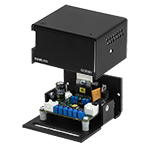
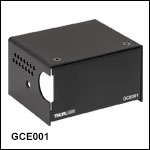
GCE001は、ガルバノシステム用のサーボドライバーボードのカバーとして使えます。
GCE001はサーボドライバーボード用のエンクロージャとしてお使いいただけます。付属のM3ネジと六角レンチを使用して、ボルトで簡単にサーボドライバーブラケットに取り付けられます。
注意: この製品は初期のサーボドライバーボードには使用できません。 詳細につきましては、当社までお問い合わせください。


Click to Enlarge
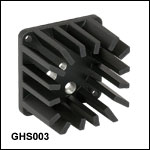
Ø12.7 mmポスト上のヒートシンクに取り付けられた2軸ガルバノミラーシステム
- 熱による動作不良を防ぐ冷却機能を追加
- 1軸および2軸のミラーマウントに直接取付け
- M4ネジ切り加工付きで、ポストに取付け可能
ガルバノミラー用ヒートシンクGHS003/Mは、1軸および2軸のミラーマウントに直接取り付けられ、デバイスの冷却およびポストアダプタとしてもお使いいただけます。取付け用のネジが製品に付属しています。
ガルバノミラーからの熱は通常は普通のマウント方法で放熱できますが、 駆動信号が急速に変化する用途では、熱が過度に蓄積してガルバノモータに動作不良が起きたり、ドライバーボードで熱制御スイッチが起動してしまうことがあります。熱制御スイッチの誤作動が繰り返し発生する場合、ヒートシンクGHS003/Mのご使用をお勧めしています。このヒートシンクはポストアダプタとしてもお使いいただけるので、ガルバノミラーアセンブリをM4ネジ切り加工付きポスト上に取り付けることができます。


Click to Enlarge
GCM001を使用して30 mmケージシステムに取り付けられたガルバノシステムGVS001。詳細はGCM001のマニュアルをご参照ください。
- 1次元ガルバノシステムの30 mmケージシステムへの取り付け
- 4側面にSM1ネジ付きポート
- 4側面にある4つの#4-40タップ穴によりØ6 mm ERシリーズケージロッドが取り付け可能
- 底面にはその他の取付け方法に対応するためにØ44.5 mmの貫通穴
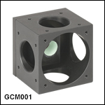
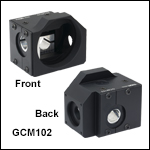
ケージシステムアダプタGCM001は、1軸ガルバノシステムGVSX01を30 mmケージシステムに取り付けるために使用します。アダプタには4つのSM1ネジ穴も付いており、また底面にはほかの取付け方法に対応するために貫通穴が開いています。
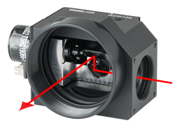
注:入力光と出力光は同一平面内にあります。

Click for Details
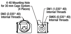
GCM102(/M)の図面
Click to Enlarge
入力ポートから入射し、2枚のガルバノミラーで反射されて、SM2ネジ付き出力ポートから出射されるビームの経路
- 2次元ガルバノシステムのポスト、30 mmケージシステム、または66 mmレールキャリッジへの取り付け
- 入力ポートはSM05内ネジならびにSM1内ネジ付き
- 出力ポートはSM2内ネジ付き
- 当社の走査レンズのラインナップに対応(対応する走査レンズについては下の表をご覧ください)
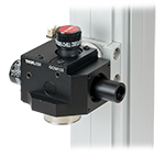
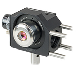
GCM102/Mには、全ての2軸小径ビームガルバノミラーシステムを取り付けることができます。ガルバノシステムをこのマウントに取り付けると、下の写真のようにポスト、30 mmケージシステム、あるいは66 mm光学レールキャリッジに取り付けることができます。
マウントのSM2内ネジ付きの出力ポートには、適切なアダプタを使用することで、走査レンズをガルバノミラーから適切な走査距離の位置に取り付けることが可能です。詳細については下の表をご覧ください。入力ポートにはSM05内ネジならびにSM1内ネジが付いており、Ø12 mm~Ø12.7 mm(Ø1/2インチ)とØ25 mm~Ø25.4 mm(Ø1インチ)レンズチューブが直接取り付けられます。さらに入力ポートの周りにある4つの#4-40タップ穴により 30 mmケージシステムに取り付け可能です。 各ポートに当社のレンズチューブ、ポート用プラグ、そして走査レンズを組み合わせた場合、システム全体が遮光されます。入力ポートと出力ポートの中心は、それぞれX軸とY軸のガルバノミラーの位置にきます。このように入力光と出力光は異なる平面内にあることにご留意ください。
マウントの底部にはM6タップ穴が2つ、M4タップ穴が3つ、そしてM3タップ穴が2つあります。各取付け穴は下の写真のように、ポストクランプアダプタC1511(/M)とC1545(/M)、Ø12 mm、Ø12.7 mm、Ø25 mm、Ø38 mm(Ø1.5インチ)ポスト、そしてレールキャリッジXT66P2(/M)ならびにXT66RCを取り付けられるよう配置されています。 様々な取付けオプションの詳細についてはマニュアルのセクション3.3をご覧ください。
X軸とY軸のガルバノミラーはユニット側面ならびに背面の2つの貫通穴を用いて取り付けます。付属の2 mm六角レンチでフレクシャークランプを動かして、ガルバノミラーの位置を固定します。取り付けに際しては、ミラーの上にあるSM05ネジ付きのビューポートをご利用できます。また、フレクシャークランプへのアクセスにはM6貫通穴2つを利用します。GCM102/Mの上面にあるSM05ネジポートとM6貫通穴は、それぞれプラグSM05PLとM6止めネジ(セットスクリュ)を取付けることで、システムの遮光を維持できます。ガルバノミラーの取り付け方法の詳細はマニュアルのセクション3.1をご覧ください。
Click to Enlarge
走査レンズLSM02を付けて、66 mmレールに取り付けたGCM102(/M)
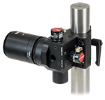
Click to Enlarge
走査レンズCLS-SLを付けて、Ø38 mm(Ø1.5インチ)ポストに取り付けたGCM102(/M)
| Scan Lens Compatibilitya | |||
|---|---|---|---|
| Item # | Scanning Distanceb | Lens Mounting Thread | Required Adapterb |
| LSM02(-BB) | 16.1 mm ± 5 mm | External M25 x 0.75 | GCMA1 |
| LSM54-850 | 17.8 mm ± 7.5 mm | SM2A33 | |
| LSM54-1050 | |||
| LSM54-1310 | |||
| LSM03(-BB) | 18.9 mm ± 5 mm | GCMA1c | |
| LSM04(-BB) | |||
| LSM03-VIS | 29.0 mm ± 5 mm | SM2A33 and SM2L03 | |
| SL50-CLS2 | 37.8 ± 4 mm | External SM30 (M30.5 x 0.5) | SM2A11 and SM2V05 |
| SL50-2P2 | |||
| LSM05(-BB) | 75.5 mm ± 5 mm | External SM2 (2.035"-40) | SM2L20 |
| CLS-SL | 58 ± 6 mm | SM2L05 and SM2V05 | |
 Products Home



 ズーム
ズーム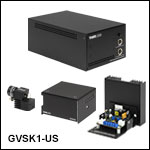
 1軸&2軸ガルバノスキャナ: ビーム径<5 mm