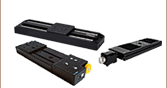
 Products Home / 電動ステージ / 電動直線移動ステージ(リニアステージ):移動量100 mm以上 / ブラシレスDCサーボモーター直線移動ステージ(リニアステージ)、ダイレクトドライブ型、移動量300 mm
ブラシレスDCサーボモーター直線移動ステージ(リニアステージ)、ダイレクトドライブ型、移動量300 mm

- 300 mm Travel at Speeds Up to 400 mm/s
- Brushless DC Servo Motor
- Bidirectional Repeatability of ±0.25 µm
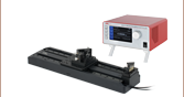
BBD301
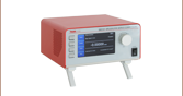
1-Channel Controller
(Sold Separately)
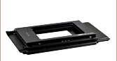
DDSA04
Platform Height Adapter
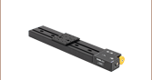
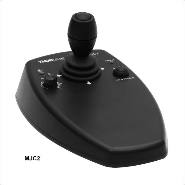
MJC2
2-Axis Joystick
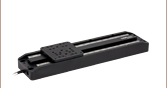
DDS300
300 mm (11.81") Servo Motor Translation Stage


Please Wait
| Key Specificationsa | |
|---|---|
| Travel Range | 300 mm (11.81") |
| Speed (Max) | 400 mm/s |
| Acceleration (Max)b | 10 000 mm/s2 |
| Bidirectional Repeatability | ±0.25 µm |
| Backlashc | N/A |
| Horizontal Load Capacity (Max)d | 10.0 kg (22.0 lbs) |
| Min Achievable Incremental Movement | 100 nm |
| Absolute On-Axis Accuracy | ±7.5 µm |
| Cable Length | 2.5 m (8.2') |
| Required Controllere | Benchtop: BBD30x; Rackmount: RBD201, MBD602 |
| Stage Dimensions (L x W x H) | 500 mm x 130 mm x 50 mm (19.69" x 5.12" x 1.97") |
| Motorized Linear Translation Stages | |
|---|---|
| 100 mm | Stepper |
| DC Servo | |
| 150 mm | Stepper |
| Stepper with Integrated Controller | |
| 220 mm | DC Servo |
| 300 mm | Stepper with Integrated Controller |
| DC Servo | |
| 600 mm | DC Servo |
| Optical Delay Line Kits | |
| Other Translation Stages | |
特長
- 移動量:300 mm
- 最大400 mm/sの高速移動
- 50 mmの薄型
- ブラシレスDCリニアサーボモータ内蔵
- 高品質で精密なリニアベアリング
- コントローラは別売り(右表参照)
- 下記のアクセサリをご用意
- 62.5 mmのプラットフォーム高さに対応する高さ調整アダプタ
- 精密手動制御用2軸または3軸ジョイスティック
当社の薄型ダイレクトドライブ直線移動ステージ(リニアステージ)DDS300/Mは、100 nmの分解能で移動量300 mm、最高速度400 mm/sの性能を有する製品です。この自動ステージは、自動アライメント、表面検査、マッピング、プロービングをはじめとする高速および高確度の位置決めが必要な用途に適しています。
ブラシレスリニアモータを内蔵した薄型設計を採用したことで、機械的な衝突や移動プラットフォームにアクセスする際の妨げの原因となる外部筐体を取り除きました。ダイレクトドライブ技術は親ネジを必要としないので、バックラッシュを排除します。また、内部のフレキシブルダクトによって機構部分が動いた時にケーブルが引っ掛かりません。精密溝付きの2つのリニアベアリングが、高い軸確度(±7.5 µm)で優れた剛性と線形性をもたらします。バックラッシュのない動作と、高分解能の閉ループ光学フィードバックが、±0.25 μmの双方向再現性をもたらします。
コントローラ
当社ではこのステージの駆動用に、1、2または3チャンネルのベンチトップ型ブラシレスDCモーターコントローラ BBD30x (別売り、下記参照)をお勧めいたします。どのコントローラもS字加減速を設定できるので、振動や衝撃の無い、高速でスムーズな位置決めが可能です。比較は「仕様」タブでご覧いただけます。高速動作(数百mm/s)で高いエンコーダ分解能(< 100nm)が求められるモーションコントロール用途に適しています。最新のデジタルとアナログ技術とともに広帯域幅およびハイパワーサーボコントロール回路を採用しています。コントローラは、既存システムに簡単に組み込むためのKinesisソフトウェアと共に発送されます。ブラシレスDCモーターコントローラの製品概要については下記をご覧ください。またはこちらをクリックして詳しい製品説明をご参照ください。
当社では19インチラック用のラックマウント型コントローラRBD201や19インチラック型モーションコントロール用シャーシMMR60x用に設計されたコントローラーモジュールMBD602もご用意しております。これらのコントローラは、ダイレクトドライブ型リニア移動ステージDDS300/Mに対応するため、使用することで多軸モータ制御による複雑なシステムのカスタマイズが可能です。
ジョイスティック
遠隔での位置決め制御用に、2軸ジョイスティックMJC2と3軸ジョイスティックMJC3をご用意しています。詳細は下記をご覧ください。なお2つの移動ステージを同時に制御するときには多軸のコントローラが必要です。
高さ調整アダプタープレート
ライザープレートDDSA04/Mを追加して、ステージのデッキ高を62.5 mmに上げることで、当社のNanoMax、MicroBlockやRollerBlockステージの高さに合わせることができます。
| Item # | DDS300(/M)a,b | |
|---|---|---|
| Travel Range | 300 mm (11.81") | |
| Speed (Max) | 400 mm/s | |
| Acceleration (Max)c | 10 000 mm/s2 | |
| Bidirectional Repeatability | ±0.25 µm | |
| Backlashd | N/A | |
| Encoder Resolution | 50 nm | |
| Minimum Achievable Incremental Movement | 100 nm | |
| Horizontal Load Capacity (Max)e | 10.0 kg (22.0 lbs) | |
| Absolute On-Axis Accuracy | ±7.5 µm | |
| Straightness/Flatness | ±4.0 µm | |
| Pitch | ±100 µrad | |
| Yaw | ±150 µrad | |
| Continuous Motor Force | 10.0 N | |
| Peak Motor Force (2 s) | 20.0 N | |
| Bearing Type | High Rigidity, Recirculating, Precision Linear Bearings | |
| Limit Switches | Magnetic Sensor at Each End of Stage | |
| Operating Temperature Rangef | 5 to 40 °C (41 to 104 °F) | |
| Motor Type | Brushless DC Linear Motor | |
| Cable Length | 2.5 m (8.2') | |
| Dimensions | 500 mm x 130 mm x 50 mm (19.69" x 5.12" x 1.97") | |
| Mass (Weight) | Excluding Cables | 5.9 kg (12.98 lbs) |
| Including Cables | 6.14 kg (13.54 lbs) | |
| Item # | BBD301 | BBD302 | BBD303 |
|---|---|---|---|
| Number of Channels | 1 | 2 | 3 |
| Drive Connector | 8 Pin DIN, Round, Female | ||
| Feedback Connector | 15-Pin D-Type, Female | ||
| Brushless Continuous Output | 2.5 A per Channel, 5 A Max All-Channel Total Output | ||
| Brushless Peak Output | 4.0 A per Channel, 5 A Max All-Channel Total Output | ||
| PWM Frequency | 40 kHz | ||
| Operating Modes | Position and Velocity | ||
| Control Algorithm | 16-Bit Digital PID Servo Loop with Velocity and Acceleration Feedforward | ||
| Velocity Profile | Trapezoidal/S-Curve | ||
| Position Count | 32 Bit | ||
| Position Feedback | Incremental Encoder | ||
| Encoder Bandwidth | 2.5 MHz (10 M Counts/sec) | ||
| Encoder Supply | 5 V | ||
| AUX Control Connector | 37-Pin D-Type Female (User Digital IO, 5 V O/P) | ||
| Front Panel Display | 4.3" Full-Color LCD, 480 x 272 Pixels | ||
| Input Power Requirements | 250 VA Voltage: 100 to 240 VAC Frequency: 47 to 63 Hz Fuse: 3.15 A | ||
| Dimensions (W x D x H) | 199.8 mm x 229.1 mm x 108.8 mm (7.87" x 9.02" x 4.28") | 250.0 mm x 279.1 mm x 108.8 mm (9.84" x 10.99" x 4.28") | 350.0 mm x 279.1 mm x 108.8 mm (13.78" x 10.99" x 4.28") |
| Mass (Weight) | 1.20 kg (2.65 lbs) | 1.70 kg (3.75 lbs) | 2.20 kg (4.85 lbs) |
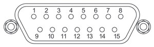
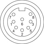
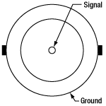
フライングリード終端にはオス型15ピンD‑サブコネクタとオス型8ピン円形DINコネクタが付いております。ピンの詳細については下記をご覧ください。
フィードバックコネクタ
モータードライブコネクタ
| Pin | Description | Pin | Description |
|---|---|---|---|
| 1 | Not Used | 9 | Ground |
| 2 | Ground | 10 | Limit Switch + |
| 3 | Not Used | 11 | Limit Switch - |
| 4 | Enc Index - | 12 | Enc Index + |
| 5 | QB - | 13 | QB + |
| 6 | QA - | 14 | QA + |
| 7a | 5 V | 15 | Not Used |
| 8a | 5 V |
| Pin | Description | Pin | Description |
|---|---|---|---|
| 1 | Motor Phase B | 5 | Stage ID |
| 2 | GND | 6 | Enable |
| 3a | Unused (Motor Phase D) | 7 | Motor Phase C |
| 4 | Motor Phase A | 8a | +5 V |
コントローラBBD30xのピン配列
ステージ
DINコネクタ、メス
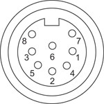
| Pin | Description | Pin | Description |
|---|---|---|---|
| 1 | Motor Phase B | 5 | Stage ID |
| 2 | GND | 6 | Enable |
| 3a | Unused (Motor Phase D) | 7 | Motor Phase C |
| 4 | Motor Phase A | 8a | +5 V |
フィードバック
D型コネクタ、メス
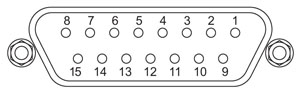
| Pin | Description | Pin | Description |
|---|---|---|---|
| 1 | Not Connected | 9 | GND |
| 2 | GND | 10 | Limit Switch + |
| 3 | Not Connected | 11 | Limit Switch - |
| 4 | Index - | 12 | Index + |
| 5 | QB - | 13 | QB + |
| 6 | QA - | 14 | QA + |
| 7a | 5 V | 15 | Not Connected |
| 8a | 5 V |
ハンドセット
Mini DINコネクタ、メス
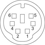
| Pin | Description | Pin | Description |
|---|---|---|---|
| 1 | RX (Controller Input) | 4 | Supply Voltage for Handset 5 V |
| 2 | Ground | 5 | TX (Controller Output) |
| 3 | Ground | 6 | Ground |
補助I/O
D型コネクタ、メス
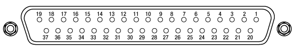
| Pin | Description | Pin | Description | Pin | Description | Pin | Description |
|---|---|---|---|---|---|---|---|
| 1 | RS232 TX | 11 | User Digital O/P 11+ | 21 | +5 V | 31 | User Digital O/P 4+ |
| 2 | RS232 RX | 12 | User Digital O/P 10- | 22 | User Digital I/P 3 | 32 | User Digital O/P 4- |
| 3 | Ground | 13 | User Digital O/P 10+ | 23 | User Digital I/P 2 | 33 | User Digital O/P 5+ |
| 4 | Differential I/P 2+ | 14 | User Digital O/P 9- | 24 | User Digital I/P 1 | 34 | User Digital O/P 5- |
| 5 | Differential I/P 2- | 15 | User Digital O/P 9+ | 25 | User Digital I/P 0 | 35 | User Digital O/P 6+ |
| 6 | Differential I/P 1- | 16 | User Digital O/P 8- | 26 | User Digital O/P 0 | 36 | User Digital O/P 6- |
| 7 | Differential I/P 1+ | 17 | User Digital O/P 8+ | 27 | User Digital O/P 1 | 37 | Ground |
| 8 | User Digital O/P 12- | 18 | User Digital O/P 7- | 28 | User Digital O/P 2 | - | - |
| 9 | User Digital O/P 12+ | 19 | User Digital O/P 7+ | 29 | User Digital O/P 3 | ||
| 10 | User Digital O/P 11- | 20 | +5 V | 30 | Ground |
USB
D型コネクタ、メス
I/O
BNCコネクタ、メス
5 V TTL
ソフトウェア
Kinesisバージョン1.14.50
このKinesisソフトウェアパッケージには、当社のKinesisシステムコントローラを制御するためのGUIが含まれています。
下記もご用意しております。
- 通信プロトコル

KinesisソフトウェアのGUI画面
当社のKinesis®ソフトウェアパッケージを用いて、当社の様々なモーションコントローラを駆動することができます。このソフトウェアは小型で低出力のシングルチャンネルドライバ(K-Cubes™など)から、高出力でマルチチャンネルのベンチトップ型ユニットやモジュール型の19インチラックナノポジショニングシステム(ラックシステムMMR60x)まで、当社Kinesisシリーズの様々なモーションコントローラの制御用にご使用いただけます。
Kinesisソフトウェアでは.NETコントロールを使用できるため、最新のC#、Visual Basic、LabVIEW™、あるいはその他の.NET対応言語を使用してカスタムプログラムを作成することができます。.NETフレームワークの使用を想定していないアプリケーションのために、ローレベルのDLLライブラリも含まれています。また、APIは各インストールに含まれています。中央シーケンスマネージャ(Central Sequence Manager)は、当社のすべてのモーションコントロール用ハードウェアの統合と同期の機能をサポートしています。
この共通のソフトウェアプラットフォームにより、ユーザは単一のソフトウェアツールを習得するだけで、あらゆるモーションコントロールデバイスを1つのアプリケーション内で組み合わせて使用することができます。このように1軸システム用から多軸システム用までのあらゆるコントローラを組み合わせ、それら全てを1台のPCの統合されたソフトウェアインターフェイスから制御できます。
このソフトウェアパッケージには2つの使い方があります。1つはGUI(グラフィカルユーザーインターフェイス)ユーティリティを用いる方法で、コントローラの到着後すぐに直接的な操作と制御を行なうことができます。もう1つは一連のプログラミングインターフェイスを用いる方法で、ご希望の開発言語によりカスタム仕様の位置決めやアライメント用のプログラムを簡単に作成することができます。
APTソフトウェア
一部の製品はAPT™ソフトウェアパッケージでも操作が可能です。ソフトウェアに関する情報は、赤いアイコン( )内の資料に記載されています。APTソフトウェアの詳細については、こちらを参照してください。
| Posted Comments: | |
nikki BAI
(posted 2024-07-25 02:54:18.413) I hope this message finds you well. I am writing to report a technical issue we have encountered Home Failure for Model DDS300M.
We tried to uninstall the Kinesis software and download the APT software for alternative solutions. However, both failed to function normally as expected.
We wonder if you could provide any remote assistance. If there are any further details or documentation required from our end, do not hesitate to ask. spolineni
(posted 2024-07-30 11:34:09.0) Thank you for reaching out about the issue with the DDS300M model. I will be in touch personally to help troubleshoot and resolve the problem. Vladislovas Cizas
(posted 2023-09-14 15:27:36.99) The DDS300/M stage connected to BBD302 controller upon homing goes to home position, then returns to the middle and then goes back. In some setups this is very uncomfortable. Is there any way to disable this? (everything up to direct hex command would be perfect). Hai Tran
(posted 2022-11-15 14:22:56.393) Hi,
I am using Kinesys app with BBD302 controller to control DDS300 linear stage. Been having a hard time talking to it. The stage is not responding to homing. I am running Kinesys 64bit for Windows. Could this be the problem.
Hai JReeder
(posted 2022-11-23 09:15:09.0) Thank you for your enquiry. In order to troubleshoot this issue, common things to check are the following: Is the channel enabled? Did the stage initialise/was a phase initialisation error received? Does this issue persist when using a different channel of the controller? What colour is the LED on the D-type connector (this indicates the status of the encoder)? What length USB cable are you using (3 m is the recommended maximum length)? I have reached out to you directly to help troubleshoot the issue. Chris Timossi
(posted 2022-10-07 15:31:02.863) We're using the DDS 300 in combination with the BBD201. I've measured the time it takes between starting the motion with the 'input trigger' and the actual start of the motion as indicated by the 'output trigger' (these trigger
signals are from the Rear Panel USER IO Connector). I setup a relative motion (2mm) on low-to-high transition of the input trigger. I setup the output trigger to low-to-high on 'in motion'. The time I see between the trigger-in and trigger-out signals varies between 25 and 50ms. Can this variation be improved? Is the BBD301 any better? DJayasuriya
(posted 2022-10-10 10:10:38.0) Thank you for your inquiry, We have got in touch with you directly to resolve your issue. andrea mura
(posted 2022-05-26 08:01:00.49) Dear Sirs
can these translation stage be controled by means of rs232, GPIB communication protocol ?
Thanks a lot for your replay.
Regards
Andrea Mura DJayasuriya
(posted 2022-05-27 08:16:53.0) Thank you for your inquiry. Internally the devices use the RS232 communication standard, and the BBD does have exposed RS232 RX and TX pins on the AUX I/O pinout.
If connected over USB, then the FTDI chip receives USB commands from the PC, and "translates" them into serial commands on the internal RX/TX headers. We have also got in touch with you directly. Andrey Kuznetsov
(posted 2021-05-26 17:59:26.973) Does it work on MacOS? DJayasuriya
(posted 2021-05-27 08:07:03.0) Thank you for your feed back. Unfortunately we do not currently support MacOS for APT or Kinesis. However with a Mac using boot camp you would be able to run windows. DJayasuriya
(posted 2021-05-27 08:07:03.0) Thank you for your feed back. Unfortunately we do not currently support MacOS for APT or Kinesis. However with a Mac using boot camp you would be able to run windows. user
(posted 2019-04-12 03:26:47.54) Hello! Does 300 mm of travel mean that if something were mounted on the center of this stage, it could travel up to 300 mm? Or is that the distance from one end of the path to the other? In other words, does the 300 mm of travel take into account the size of the stage that is moving? rmiron
(posted 2019-04-12 06:14:10.0) Response from Radu at Thorlabs: 300 mm is the full travel range of the stage, from one end to the other. More specifically, it is the distance between the two end limit switches. Anything mounted on DDS300(/M) can move by 300 mm. The total length of the stage is 500 mm, as is shown in the CAD drawings posted under "Docs", on the main tab. I hope this answers your question. gert
(posted 2017-06-27 15:43:42.607) Hi,
We want to operate a DDS300-E at a constant velocity in the range of 1 to 10 mm/s. Would it be possible to give us a spec or estimate for the stability of the velocity that can be achieved with this stage?
Thank you,
Gert awebber-date
(posted 2017-07-03 10:36:45.0) Response from Alex at Thorlabs: When trying to run servo motors at these extremely low velocities there will be some fluctuations in the speed of the stage. We evaluated a DDS220's performance at various set speeds using interferometer when carrying a load of 500g and after 5 million cycles of soak testing,typical velocity fluctuations were ±0.5mm at 10mm/s and ±0.3mm at 1mm/s (with a background noise of 0.006mm/s when stationary). sipos
(posted 2015-09-25 18:06:31.23) Dera Sir/Madam,
Can this translator be mounted vertically? In this case what is the maximum torque load? GHow does this effect the Pitch/yaw specs?
Best regards
Áron SIPOS rcapehorn
(posted 2015-09-30 09:40:29.0) Response from Rob at Thorlabs: Unfortunately our brushless stages are not designed to be run vertically. The main problem is that when the stage is powered down there is nothing to hold the moving world in place, so it will drop back to the home position, which could result in damage to the stage.
If you need to use a stage in a vertical configuration then you would need to use something with a lead screw such as the LTS300/M, the main disadvantage with this type of stage is that the maximum velocity will be much slower and also the positional resolution is not as good as with the DDS300/M stage as there is no encoder in the LTS300/M but this it the longest vertical travel stage that Thorlabs can currently offer. |
電動リニアステージ
電動の直線移動ステージとしては、ピエゾ駆動の20 µm移動ステージからダイレクトドライブ方式の600 mm移動ステージまで、様々な最大移動量の製品をご用意しております。ステージの多くは、それらを用いてXY軸やXYZ軸などの多軸ステージを構築することができます。ファイバ結合用としては、多軸ステージのページをご覧ください。標準の電動ステージを用いるよりも精密な調整が可能です。直線移動ステージのほかに、電動の回転ステージおよびゴニオステージもご用意しております。また手動移動ステージもございます。
ピエゾステージ
これらのステージでは、様々な駆動機構にピエゾ素子が組み込まれています。ステージORIC®シリーズでは、「スティック-スリップ」と呼ばれる摩擦特性を利用したピエゾ慣性アクチュエータが用いられており、それにより長い移動距離が得られています。移動ステージNanoflex™シリーズは、手動アクチュエータに加えて標準的なピエゾアクチュエータが用いられています。ステージElliptec®シリーズでは共振ピエゾモータが用いられており、共振に伴うモータ先端の楕円形の動きで可動プラットフォームを押したり引いたりします。Z軸ステージLPS710E/Mにはピエゾ移動に対する機械的な増幅機構が組み込まれており、またそれに適したコントローラが付属しています。
| Piezoelectric Stages | ||||
|---|---|---|---|---|
| Product Family | ORIC® PDXZ1 Closed-Loop 4.5 mm Vertical Stage | ORIC® PD2 Open-Loop 5 mm Stage | ORIC® PDX2 Closed-Loop 5 mm Stage | |
| Click Photo to Enlarge |  |  |  | |
| Travel | 4.5 mm | 5 mm | ||
| Speed | 1 mm/s (Typ.)a | 10 mm/s (Typ. Max)b | 8 mm/s (Typ.)c | |
| Drive Type | Piezoelectric Inertia Drive | |||
| Possible Axis Configurations | Z | X, XY, XYZ | ||
| Mounting Surface Size | 45.0 mm x 42.0 mm | 13 mm x 13 mm | ||
| Additional Details | ||||
| Piezoelectric Stages | |||||
|---|---|---|---|---|---|
| Product Family | ORIC® PD1 Open-Loop 20 mm Stage | ORIC® PD1D Open-Loop 20 mm Monolithic XY Stage | ORIC® PDX1 Closed-Loop 20 mm Stage | ORIC® PD3 Open-Loop 50 mm Stage | |
| Click Photo to Enlarge |  |  |  |  | |
| Travel | 20 mm | 50 mm | |||
| Speed | 3 mm/s (Typ. Max)a | 20 mm/s (Typ. Max)b | 10 mm/sc | ||
| Drive Type | Piezoelectric Inertia Drive | ||||
| Possible Axis Configurations | X, XY, XYZ | XY, XYZ | X, XY, XYZ | X, XY, XYZ | |
| Mounting Surface Size | 30 mm x 30 mm | 80 mm x 30 mm | |||
| Additional Details | |||||
| Piezoelectric Stages | ||||||
|---|---|---|---|---|---|---|
| Product Family | Nanoflex™ 20 µm Stage with 5 mm Actuator | Nanoflex™ 25 µm Stage with 1.5 mm Actuator | Elliptec® 28 mm Stage | Elliptec® 60 mm Stage | LPS710E 1.1 mm Vertical Stage | |
| Click Photo to Enlarge |  |  |  |  |  | |
| Travel | 20 µm + 5 mm Manual | 25 µm + 1.5 mm Manual | 28 mm | 60.0 mm | 1.1 mm | |
| Maximum Velocity | - | 180 mm/s | 90 mm/s | - | ||
| Drive Type | Piezo with Manual Actuator | Resonant Piezoelectric Motor | Amplified Piezo | |||
| Possible Axis Configurations | X, XY, XYZ | X | Z | |||
| Mounting Surface Size | 75 mm x 75 mm | 30 mm x 30 mm | 15 mm x 15 mm | 21 mm x 21 mm | ||
| Additional Details | ||||||
ステッピングモーターステージ
こちらの移動ステージは脱着型あるいは内蔵型のステッピングモータを用いており、また300 mmまでの長い移動量が可能です。ステージの多くは多軸構成(PLSXY)や、多軸ステージ(PLSX、LNRシリーズ、NRTシリーズ、LTSシリーズ)への組み込みが可能です。ステージMLJ150/Mは高荷重にも対応する垂直移動ステージです。
| Stepper Motor Stages | |||||
|---|---|---|---|---|---|
| Product Family | PLSX with and without PLST(/M) Top Plate 1" Stage | PLSXY with and without PLST(/M) Top Plate 1" Stage | LNR Series 25 mm Stage | LNR Series 50 mm Stage | |
| Click Photo to Enlarge |  |  |  |  | |
| Travel | 1" | 25 mm | 50 mm | ||
| Maximum Velocity | 7.0 mm/s | 2.0 mm/s | 50 mm/s | ||
| Possible Axis Configurations | X, XY | X, XY, XYZ | X, XY, XYZ | ||
| Mounting Surface Size | 3" x 3" | 60 mm x 60 mm | 100 mm x 100 mm | ||
| Additional Details | |||||
| Stepper Motor Stages | ||||||
|---|---|---|---|---|---|---|
| Product Family | NRT Series 100 mm Stage | NRT Series 150 mm Stage | LTS Series 150 mm Stage | LTS Series 300 mm Stage | MLJ250 50 mm Vertical Stage | |
| Click Photo to Enlarge |  |  |  |  |  | |
| Travel | 100 mm | 150 mm | 150 mm | 300 mm | 50 mm | |
| Maximum Velocity | 30 mm/s | 50 mm/s | 3.0 mm/s | |||
| Possible Axis Configurations | X, XY, XYZ | X, XY, XYZ | Z | |||
| Mounting Surface Size | 84 mm x 84 mm | 100 mm x 90 mm | 148 mm x 131 mm | |||
| Additional Details | ||||||
DCサーボモーターステージ
脱着型あるいは内蔵型のDCサーボモータを用いた直線移動ステージをご用意しております。これらのステージは薄型で、多軸ステージの構築が可能です。
| DC Servo Motor Stages | ||||
|---|---|---|---|---|
| Product Family | MT Series 12 mm Stages | PT Series 25 mm Stages | MTS Series 25 mm Stage | MTS Series 50 mm Stage |
| Click Photo to Enlarge |  |  |  |  |
| Travel | 12 mm | 25 mm | 25 mm | 50 mm |
| Maximum Velocity | 2.6 mm/s | 2.4 mm/s | ||
| Possible Axis Configurations | X, XY, XYZ | X, XY, XYZ | ||
| Mounting Surface Size | 61 mm x 61 mm | 101.6 mm x 76.2 mm | 43 mm x 43 mm | |
| Additional Details | ||||
| DC Servo Motor Stages | ||||
|---|---|---|---|---|
| Product Family | M30 Series 30 mm Stage | M30 Series 30 mm Monolithic XY Stage | M150 Series 150 mm XY Stage | KVS30 30 mm Vertical Stage |
| Click Photo to Enlarge |  |  |  |  |
| Travel | 30 mm | 150 mm | 30 mm | |
| Maximum Velocity | 2.4 mm/s | X-Axis: 170 mm/s Y-Axis: 230 mm/s | 8.0 mm/s | |
| Possible Axis Configurations | X, Z | XY, XZ | XY | Z |
| Mounting Surface Size | 115 mm x 115 mm | 272.4 mm x 272.4 mm | 116.2 mm x 116.2 mm | |
| Additional Details | ||||
ダイレクトドライブステージ
こちらの薄型ステージにはブラシレスDCサーボモータが内蔵されており、バックラッシュの無い高速移動が可能です。電源が入ってないときは、ステージのプラットフォームにはほとんど慣性が無く、実質的にフリーラン状態になります。そのため電源が入ってないときにステージのプラットフォームが定位置に留まる必要のある用途には適していません。これらのステージを垂直方向に取付けることは推奨しません。
| Direct Drive Stages | |||||
|---|---|---|---|---|---|
| Product Family | DDS Series 50 mm Stage | DDS Series 100 mm Stage | DDS Series 220 mm Stage | DDS Series 300 mm Stage | DDS Series 600 mm Stage |
| Click Photo to Enlarge |  |  |  |  |  |
| Travel | 50 mm | 100 mm | 220 mm | 300 mm | 600 mm |
| Maximum Velocity | 500 mm/s | 300 mm/s | 400 mm/s | 400 mm/s | |
| Possible Axis Configurations | X, XY | X, XY | X | X | |
| Mounting Surface Size | 60 mm x 52 mm | 88 mm x 88 mm | 120 mm x 120 mm | ||
| Additional Details | |||||

 ズーム
ズームDDS300/Mは高速移動と高い位置正確性が特長で、データを収集しながら同時にカメラやプローブを一定の速度で移動する必要がある表面マッピングや解析用途に適しています。別売りのジョイスティックMJC2またはMJC3(下記参照)を用いると高い確度で微細な位置決めと制御が可能となります。
注:
このステージは垂直方向(Z軸)の移動には適していません。また、電源が入ってないときのプラットフォームはロックされていない状態(フリーラン状態)になります。そのため、電源が入ってないときには定めた位置に留まっていることが求められる用途には適しません。

 ズーム
ズーム当社では、上記のステージの制御用として、BBDシリーズブラシレスDCサーボモーターコントローラをお勧めします。コントローラはチャンネル数に応じて選択できます。単独のステージを使用する場合は、BBD301をご使用いただけます。ジョイスティックMJC2も使用する場合はBBD302をお勧めします。そのほかのアクセサリも使用する場合は、3チャンネルコントローラBBD303をお使いいただけます。3チャンネルのすべてを、ジョイスティックMJC3を介して制御できます。
S字加減速が自由に設定できるため、振動や衝撃の無い、スムーズな高速位置決めが可能です。したがって、これらのコントローラは、高速動作(数100mm/s)と高いエンコーダ分解能を必要とするモーションコントロールに適しています。このBBDシリーズコントローラは、最新のデジタルおよびアナログ技術と、高帯域で高パワーのサーボコントロール回路を使用しており、ブラシレスDCサーボモータを最大連続出力電流2.5 A (型番BBD301)または5 A (型番BBD302とBBD303)で駆動できるように設計されています。
これらのDCサーボコントローラでは、当社のKinesis®によるコントロール&プログラミングインターフェイスをご利用いただくことができますので、自動モーションコントロールのアプリケーションに簡単に組み込むことができます。PCとのインターフェイスとして、柔軟性を高めるためにUSBとRS232の両方を備えており、付属のソフトウェア開発キット(SDK)を用いてステージのPC自動制御が可能です。SDKはWindowsで動作する全ての主要な開発言語をサポートしており、ActiveXライブラリまたは従来のダイナミックリンクライブラリ(DLL)の形式で提供されます。
USB接続のプラグアンドプレイによって簡単にPCでの操作が可能になります。多軸のモーションコントロールを行う場合でも、標準的なUSBハブを介して複数のユニットを1台のPCに接続できます。この機能と使いやすいソフトウェアを組み合わせることで、複雑な動作シーケンスを短時間でプログラムして実行することができます。詳細は、ブラシレスDCサーボモーターコントローラの製品紹介ページをご参照下さい。

 ズーム
ズーム- USB HIDプロトコルを使用した信頼性の高いジョイスティック
- ジョイスティックノブによる2軸または3軸制御
- 高速または高精度の移動を実現する2種類のモード
- 感度調整のための速度ダイヤル
- リモート手動操作が可能
- PCを用いて再プログラム可能
- 人間工学に基づいた設計
ジョイスティックMJC2およびMJC3は顕微鏡ユーザ向けに設計されており、ステージの位置決めを手動で直感的に行うことができます。MJC2にはXY制御用に2軸のジョイスティックノブ、MJC3にはXYZ制御用に3軸のジョイスティックノブが付いています。どちらのジョイスティックノブも上下左右に動かすことができますが、MJC3のジョイスティックノブでは第3軸の制御機能として時計回りまたは反時計回りにひねることができます。また、ジョイスティックには高速移動と高精度移動を切り替えるプッシュボタンと、速度制御を微調整するためのスピードダイヤルも付いています。ほとんどの用途では、コントローラに保存されたデフォルトのパラメータ設定のままですぐにお使いいただくことができ、それ以上の設定は不要です。そのような使い方をするときはホストPCに接続する必要もなく、真のリモート操作が可能です。PCを使用してパラメータを再設定したとき、それをペアリングしたコントローラにも保存できます。そのため、PCとの接続を外してもリモート操作を継続できます。
ジョイスティックMJC2およびMJC3は、当社のベンチトップ型ブラシレスDCモーターコントローラ、ラックマウント型ブラシレスDCサーボコントローラ、 ブラシレスDCモーターコントローラーモジュール 、ブラシレスDCモーターコントローラーモジュール、ステッピングモーター用コントローラに対応します。これらのコントローラやUSB HIDクラスを使うセットアップと組み合わせて使用できるように、ジョイスティックにはMini-DINポートとUSB Type-Cポートの両方が付いています。また、6ピンMini-DINプラグ-プラグケーブルとUSB 3.1 Type-A - Type-Cケーブルの2本のケーブルが付属します。USB HIDを介したジョイスティックの構成やセットアップについての詳細は、型番横の赤いアイコン( )をクリックしてマニュアルをご覧ください。

 ズーム
ズームClick to Enlarge
高さ調整アダプタDDSA04(/M)を使用することにより、ステージDDS300のデッキ高が3軸ステージMAX311Dの高さに合います。
- ステージのデッキ高(62.5 mm)が当社のNanoMax300、MicroBlock、ならびにRollerBlockステージと同じになる高さ調整アダプタ
- 取付後の光軸高さ: 75.0 mm(当社の溝付きアクセサリ使用時)
- M6、M4、M3タップ穴が16個ずつ、計48個のタップ穴の配列
高さ調整アダプタDDSA04/Mは、移動ステージDDS300/Mのデッキ高を当社のNanoMax 300、MicroBlock、RollerBlockステージと同じ62.5 mmまで上げる設計となっております。 このアダプタにより移動ステージDDS300/Mに当社の溝付きアクセサリを使用することが可能となります。その時の、光軸の高さは75.0 mmとなります。 高さ調整アダプタは、M6 x 10 mmキャップスクリュ(付属しません)を使用して移動プラットフォームに固定します。