 Products Home
Microscope Objectives for Life Sciences, Dry

- Infinity-Corrected Dry Microscope Objectives
- Axial Color Correction Options Across the Visible and NIR Spectrum
- Designed for Widefield Fluorescence or Multiphoton Imaging Applications
- 15X, 10X, 4X, 2X, or 1X Magnification
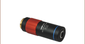
TL10X-2P
10X Super Apochromat Objective for Two-Photon Microscopy
TL2X-SAP
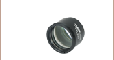
2X Super Apochromat Objective
TL1X-SAP
1X Super Apochromat Objective
TL15X-2P
15X Plan Apochromat VIS+ Objective for Two-Photon Microscopy


Please Wait

| Objective Lens Selection Guide |
|---|
| Objectives |
| Microscopy Objectives for Life Sciences, Dry Microscopy Objectives, Dry Microscopy Objectives, Oil Immersion Physiology Objectives, Water Dipping or Immersion Phase Contrast Objectives Long Working Distance Objectives Reflective Microscopy Objectives UV Microscopy Objectives VIS and NIR Focusing Objectives |
| Scan Lenses and Tube Lenses |
| Scan Lenses Infinity-Corrected Tube Lens |
| Webpage Features | |
|---|---|
 |
Zemax blackbox files for the objectives on this page can be accessed by clicking this icon below. |

Did You Know?
Multiple optical elements, including the microscope objective, tube lens, and eyepieces, together define the magnification of a system. See the Magnification & FOV tab to learn more.

Click for Details
Thorlabs maintains the labeling convention shown above for all of its super apochromatic microscope objectives. (See the Objective Tutorial tab for more information about microscope objective types.)

Click for Details
Thorlabs maintains the labeling convention shown above for its TL15X-2P objective. (See the Objective Tutorial tab for more information about microscope objective types.)
Features
- Infinity-Corrected Super Apochromatic and Enhanced Visible Design
- Antireflection (AR) Coatings:
- 15X and 10X Objectives: 400 nm - 1300 nm
- 4X and 2X Objectives: 350 nm - 700 nm
- 1X Objective: 420 nm - 700 nm
- Numerical Aperture (NA) Up to 0.70
- Ideal for Brightfield, Fluorescence, Multiphoton, or Confocal Imaging Applications
- Magnifications Specified for Use with a 200 mm Tube Lens
Thorlabs' apochromatic microscope objectives for life sciences provide axial color correction across the visible range and a flat field of focus in a variety of imaging modalities without introducing vignetting. These objectives are designed for use with a tube lens focal length of 200 mm and have optical elements that are AR-coated for improved transmission. Our 15X and 10X objectives are designed for two-photon imaging. These objectives have 2.60 mm and 7.77 mm working distances respectively and feature a correction collar and optical thickness scale, allowing the objectives' focus to be adjusted for a variety of media that may be present between the objective and the sample, such as aqueous solutions and cover glasses (see the Correction Collar tab for details). Our 4X and 2X objectives pair their low magnifications with numerical apertures (NA) of 0.20 or 0.10, respectively, making them ideal for widefield imaging, while our 1X telecentric objective is ideal for machine vision applications (see Telecentric Tutorial tab). Note that these objectives are not suitable for water-dipping, water-immersion, or oil-immersion techniques.
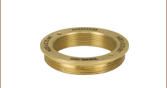
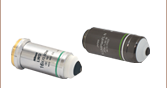
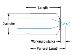
Every objective housing is engraved with the Item #, magnification, NA, and wavelength range. Each objective is shipped in an objective case comprised of a lid and container. The threading for each objective is given below; to use the objectives with a different thread standard, please see our microscope objective thread adapters.
Mounting the objectives on this page together or in combination with other objectives may require parfocal length extenders, which allow users to match parfocal lengths and switch between objectives of different magnifications mounted in a turret or nosepiece without significant refocusing.
| Item # | TL15X-2P | TL10X-2P | TL4X-SAP | TL2X-SAP | TL1X-SAPa |
|---|---|---|---|---|---|
| Specifications | |||||
| Magnificationb | 15X | 10X | 4X | 2X | 1X |
| Numerical Aperture (NA) | 0.70 | 0.50 | 0.20 | 0.10 | 0.03 |
| AR Coating Range | 400 - 1300 nm | 350 - 700 nm | 420 - 700 nm | ||
| AR Coating Reflectance Per Surface |
Rabs < 3% (400 - 450 nm) Rabs < 2% (450 - 1300 nm) @ 0° - 25° AOI |
Ravg < 0.5% @ 0° AOI | |||
| Total Transmission (Click to Enlarge) |
Raw Data |
Raw Data |
Raw Data |
Raw Data |
Raw Data |
| Axial Colorc | Diffraction Limited over |
Diffraction Limited over 440 - 700 nm | |||
| Field of View | Ø1.5 mm | Ø2.2 mm | Ø5.5 mm | Ø11 mm | Ø22 mm |
| Working Distanced | 2.6 mme | 7.77 mm | 17.0 mm | 56.3 mm | 8.0 mm |
| Effective Focal Length (EFL) | 13.3 mm | 20 mm | 50 mm | 100 mm | 200 mm |
| Entrance Pupil Diameter | 18.6 mmf | 20.0 mmf | 20.0 mmg | 20.0 mmg | 12.0 mmg |
| Resolutionh | 0.5 µm | 0.7 µm | 1.7 µm | 3.4 µm | 11.2 µm |
| Parfocal Lengthd | 75.0 mm | 95.0 mm | 60.0 mmi | 95.0 mm | 95.0 mm |
| Diameterd | 38.1 mm | 43.2 mm | 30.5 mm | 32.6 mm (Without Wave Plate) |
|
| 34.5 mm (With Wave Plate) |
|||||
| Lengthd | 76.9 mm | 90.4 mm | 46.4 mm | 43.5 mm | 85.5 mm (Without Wave Plate) |
| 90.6 mm (With Wave Plate) |
|||||
| Housing Threads | M32 x 0.75 | M25 x 0.75 | |||
| Thread Depth | 4.5 mm | 3.2 mm | 3.6 mm | 3.2 mm | 3.8 mm |
| Field Numberj | 22 | ||||
| Design Tube Lens Focal Lengthk | 200 mm | ||||
| Cover Glass Thickness | 0 - 2.8 mm | 0 - 2.6 mm | 0 - 5.0 mm | 0 - 5.0 mm | 0 - 5.0 mm |
| Recommended Microscopy Techniques | |||||
| Confocal | |||||
| Two-Photon | - | - | - | ||
| Brightfield | |||||
| Darkfield | |||||
| Dodt | |||||
| DIC | - | - | |||
| Fluorescence | |||||
Objective Performance Data
Various tests were carried out to demonstrate the specified performance of each of our objectives. Click the links below for more information about a specific objective.
15X Objective Performance Graphs
Click here for raw data for all plots.
Click to Enlarge
Transmission of the TL15X-2P Objective. The blue shaded region denotes the wavelength range of the AR coating.

Click to Enlarge
Axial color describes the shift in the image plane across the operating wavelength range of the 15X apochromatic improved visible microscope objective. The pink shaded region denotes diffraction-limited performance. Diffraction-limited performance can be shifted to the NIR with refocusing.

Click to Enlarge
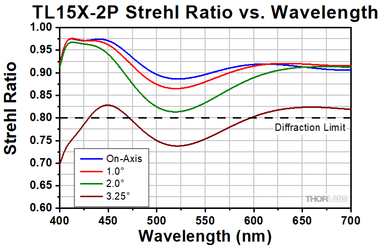
The Strehl Ratio is a quantitative measurement of optical image formation quality. The Strehl Ratio for the TL15X-2P over its field of view is shown in the graph above.
Click to Enlarge
This graph shows the Strehl Ratio of the TL15X-2P over the objective's visible performance band.
Click to Enlarge
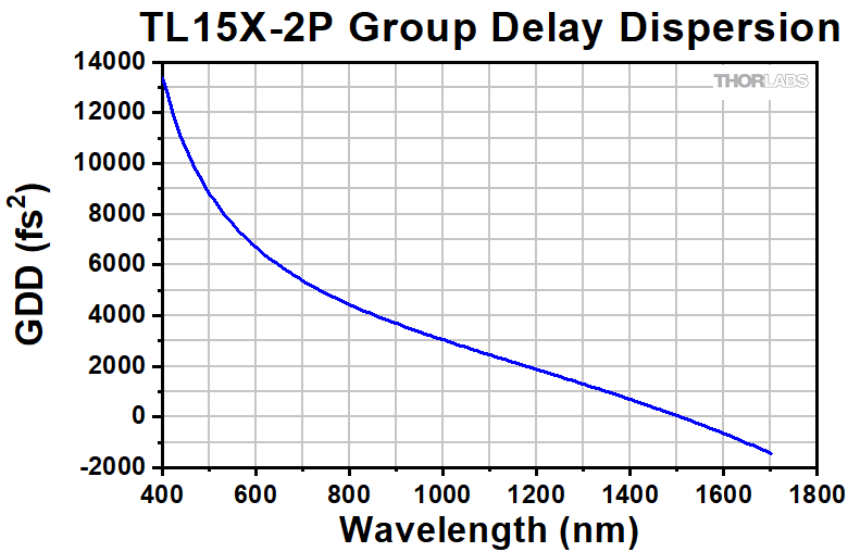
The Group Delay Dispersion (GDD) represents how the duration of an ultrafast laser pulse will increase through an optical path length. The simulated GDD for the TL15X-2P objective is shown in the graph above.
10X Objective Performance Graphs
Click here for raw data for all plots.
Click to Enlarge
Transmission of the TL10X-2P Objective. The blue shaded region denotes the wavelength range of the AR coating.

Click to Enlarge
Axial color describes the shift in the image plane across the operating wavelength range of the 10X super apochromatic microscope objective. The pink shaded region denotes diffraction-limited performance. Diffraction-limited performance can be shifted to the NIR with refocusing.

Click to Enlarge
The Strehl Ratio is a quantitative measurement of optical image formation quality. The Strehl Ratio for the TL10X-SAP over its field of view is shown in the graph above.

Click to Enlarge
This graph shows the Strehl Ratio of the TL10X-2P over the objective's visible performance band.

Click to Enlarge
The Group Delay Dispersion (GDD) represents how the duration of an ultrafast laser pulse will increase through an optical path length. The simulated GDD for the TL10X-2P objective is shown in the graph above.
4X Objective Performance Graphs
Click here for raw data for all plots.
Click to Enlarge
Transmission of the TL4X-SAP Objective. The blue shaded region denotes the wavelength range of the AR coating.

Click to Enlarge
Axial color describes the shift in the image plane across the operating wavelength range of the 4X super apochromatic microscope objective. The pink shaded region denotes diffraction-limited performance.

Click to Enlarge
The Strehl Ratio is a quantitative measurement of optical image formation quality. The Strehl Ratio for the TL4X-SAP over its field of view is shown in the graph above.

Click to Enlarge
This graph shows the Strehl Ratio of the TL4X-SAP over the objective's full operating wavelength range.
2X Objective Performance Graphs
Click here for raw data for all plots.
Click to Enlarge
Transmission of the TL2X-SAP Objective. The blue shaded region denotes the wavelength range of the AR coating.

Click to Enlarge
Axial color describes the shift in the image plane across the operating wavelength range of the 2X super apochromatic microscope objective. The pink shaded region denotes diffraction-limited performance.

Click to Enlarge
The Strehl Ratio is a quantitative measurement of optical image formation quality. The Strehl Ratio for the TL2X-SAP over its field of view is shown in the graph above.

Click to Enlarge
This graph shows the Strehl Ratio of the TL2X-SAP over the objective's full operating wavelength range.
1X Objective Performance Graphs
Click here for raw data for all plots.
Click to Enlarge
Transmission of the TL1X-SAP Objective. The blue shaded region denotes the wavelength range of the AR coating.

Click to Enlarge
Axial color describes the shift in the image plane across the operating wavelength range of the 1X super apochromatic microscope objective. The pink shaded region denotes diffraction-limited performance.

Click to Enlarge
The Strehl Ratio is a quantitative measurement of optical image formation quality. The Strehl Ratio for the TL1X-SAP over its field of view is shown in the graph above.

Click to Enlarge
This graph shows the Strehl Ratio of the TL1X-SAP over the objective's full operating wavelength range.
| Chromatic Aberration Correction per ISO Standard 19012-2 | ||
|---|---|---|
| Objective Class | Common Abbreviations | Axial Focal Shift Tolerancesa |
| Achromat | ACH, ACHRO, ACHROMAT | |δC' - δF'| ≤ 2 x δob |
| Semiapochromat (or Fluorite) | SEMIAPO, FL, FLU | |δC' - δF'| ≤ 2 x δob |δF' - δe| ≤ 2.5 x δob |δC' - δe| ≤ 2.5 x δob |
| Apochromat | APO | |δC' - δF'| ≤ 2 x δob |δF' - δe| ≤ δob |δC' - δe| ≤ δob |
| Super Apochromat | SAPO | See Footnote b |
| Improved Visible Apochromat | VIS+ | See Footnotes b and c |
顕微鏡用対物レンズの各部名称
各部名称をクリックすると詳細をご覧いただけます。
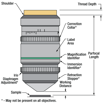
上の顕微鏡用対物レンズは1例です。アスタリスク(*)で示されている機構はすべての対物レンズに備わっているわけではありません。必要性や用途に応じて、追加されたり、位置が変更されたり、あるいは削除されたりしています。
対物レンズのチュートリアル
このチュートリアルでは対物レンズの様々な機構や表示、およびそれらが示す対物レンズの性能について説明します。
対物レンズの種類と収差補正
対物レンズは一般にその種類によって分類されています。対物レンズの種類によって、対物レンズがどのようにイメージング収差を補正するかが簡単に分かります。 対物レンズの種類によって示される収差補正には、像面湾曲と色収差の2つがあります。
像面湾曲(またはペッツヴァルの湾曲)は、対物レンズの焦点面が球面状に湾曲している状態を表します。この収差があるレンズでは、像面の中心に焦点を合わせると四隅が焦点から外れてしまうため、ワイドフィールド観察やレーザ走査などが困難になります。種類が「Plan」から始まる対物レンズの場合は、その焦点面が平面になるように補正されています。
また結像に際して色収差が生じる場合があり、そのときには1点から放射された光は波長により分散して1点に焦点を結びません。対物レンズによっては、性能と設計の複雑性の間でバランスをとるために、有限数のターゲット波長においてそれらの収差を補正するものがあります。
5種類の一般的な対物レンズを右表に示します。このうち3種類のみがISO 19012-2: Microscopes -- Designation of Microscope Objectives -- Chromatic Correctionで定義されています。より良い性能を表すために、当社ではISO規格には無い2つの種類を追加しています。
浸漬方法
詳細についてはそれぞれの対物レンズの画像をクリックしてご覧ください。
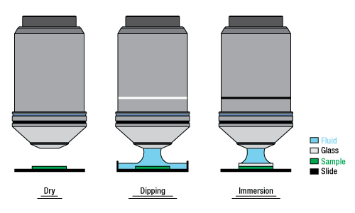
対物レンズは、イメージングのための光が透過する媒質によって分類することができます。ドライ対物レンズは空気中で使用しますが、液浸(DippingまたはImmersion)対物レンズは対物レンズと試料の間に液体を介在させて使用するように設計されています。
| 用語解説 | |
|---|---|
| 後方焦点距離と無限遠補正 | 後方焦点距離は、中間結像面の位置を定義します。最新の対物レンズではこの面が無限遠の位置に置かれ(無限遠補正と呼ばれる)、そのようなレンズには(∞)が記されています。無限遠補正対物レンズは、対物レンズと接眼レンズの間にチューブレンズを挿入して使用するように設計されています。顕微鏡システムの互換性向上に加えて、このような無限遠補正された空間が対物レンズとチューブレンズの間にあることで、ほかのモジュール(ビームスプリッタ、フィルタ、同焦点距離エクステンダなど)を光路内に配置することが可能になります。 なお、旧型の対物レンズや特殊なタイプの対物レンズは、有限の後方焦点距離で設計されている場合があります。当初、有限の後方焦点距離の対物レンズは、顕微鏡の接眼レンズに直接対応するように作られていました。 |
| 入射瞳径(EP) | 入射瞳径(EP)は有効口径とも呼ばれ、対物レンズを適切に機能させるために使用すべき適切なビーム径に対応します。 EP = 2 × NA × Effective Focal Length (入射瞳径 = 2 × 開口数(NA) × 有効焦点距離) |
| 視野数と視野 | 視野数は、物体空間の視野の直径(mm単位)に対物レンズの倍率を乗じた値です。 Field Number = Field of View Diameter × Magnification(視野数= 視野直径 × 倍率) |
| 倍率 | 対物レンズの倍率(M)はチューブレンズの焦点距離(L)を対物レンズの焦点距離(F)で割った値です。有効焦点距離はEFLと略記されることがあります。 M = L / EFL . システムの総合倍率は、対物レンズの倍率に接眼レンズまたはカメラチューブの倍率を乗じて得られます。顕微鏡用対物レンズ筐体に示されている倍率は、その対物レンズに対応する焦点距離のチューブレンズと組み合わせてお使いになる場合にのみ正しい値です。対物レンズには、倍率を示す色のリングが付いています。これは比較的どのメーカでも共通しています。詳細は上の「顕微鏡用対物レンズの各部名称」をご覧ください。 |
| 開口数(NA) | 開口数は、対物レンズの最大受光角を表す無次元量です。一般的には下の式で表されます。 NA = ni × sinθa ここでθaは対物レンズの最大受光角度の1/2(半角)、niは媒質の屈折率です。典型的な媒質は空気ですが、水や油などほかの物質の場合もあります。 |
| 作動距離 | 作動距離(WD)は対物レンズの設計に依存しており、対物レンズの前面から試料の上部(カバーガラスを使用しない場合)まで、またはカバーガラスの上部までの距離を表します。対物レンズに刻印されているカバーガラスの厚さの仕様値により、カバーガラスを使用すべきかどうかが分かります。 |
カバーガラス(カバースリップ)は含水試料の上にのせる薄いガラスで、イメージングするための平面を作ります。
最も一般的な標準のカバーガラス#1.5は、厚さが0.17 mmに設計されています。製造工程により実際の厚さにはばらつきがある場合があります。対物レンズによっては補正環が付いていますが、これは内部の光学素子の相対位置を調整して、カバーガラスの厚さの違いを補正するのに使用されます。なお、多くの対物レンズにはカバーガラスの厚さの違いを補正する機能は無く、その場合には補正環は付いていません。例えば、カバーガラス#1.5専用に設計されている対物レンズなどがございます。補正環は上の図のような上部にではなく、対物レンズの下部にある場合もあります。

Click to Enlarge
上のグラフは、632.8 nmの光を使用したときの、カバーガラスの厚さと球面収差の大きさの関係を示しています。厚さ0.17 mmの一般的なカバーガラスを使用する場合、NA 0.40までの対物レンズではカバーガラスによる球面収差が回折限界を超えることはありません。

Click to Enlarge
厚さ#1.5(0.17 mm)、屈折率1.51のカバーガラスによる画質への影響(波長は632.8 nm)

Click for Details
厚さと光円錐は分かりやすさのために誇張されています。
補正環とカバーガラスの補正
カバーガラスは、しばしば観察対象物の上部にフラットな面をつくるために水性試料の上に置かれます。これにより試料に焦点を合わせやすくなりますが、ガラスにより最終的な画像に球面収差が生じる場合があります。右のグラフは、波長632.8 nmにおけるカバーガラスの厚さと球面収差の関係を示しています。カバーガラスが典型的な厚さである0.17 mmの場合、NAが0.40以下の対物レンズではカバーガラスによる球面収差は回折限界以下です。
当社の対物レンズTL15X-2PおよびTL10X-2Pには補正環が付いています。補正環は、カバーガラスの厚さの違いによる影響を内部の光学素子の相対位置を調整することで補正し、球面収差を抑えて回折限界性能が得られるように補助します。 補正環には2つの目盛が付いています。1つは屈折率1.51のカバーガラスの厚さの違いを補正するためのもので、もう1つは対物レンズと焦点面との間の物質の光学的厚さを補正するためのものです(空気は無視しています)。2番目の目盛は、関心領域が溶液内にある場合に便利です。どちらの目盛もミリ単位で印されています。
対物レンズと試料の間にある空気以外のすべての物質による光学的厚さを求めるには、各物質の厚さとその屈折率の乗数の和を求めます。 例として、対物レンズTL10X-2Pからの光が右下の図のように空気(7.30 mm)、カバーガラス(0.17 mm)、および食塩水(1.00 mm)を透過して焦点を結んでいる場合を考えてみましょう。適切な補正環の設定値を求めるには、各物質の厚さtにそれぞれの屈折率nを乗じます(空気は無視します)。
光学的厚さの設定値 = ∑txnx
t1n1 + t2n2 = 0.17 mm × 1.51 + 1.00 mm × 1.33 = 1.59 mm
| Examples of Optical Thickness Calculationsa | ||
|---|---|---|
| Glass Thickness (n = 1.51) | Water Thickness (n = 1.33) | Optical Thickness Collar Setting |
| 0.00 mm | 0.00 mm | 0.00 mm |
| 0.50 mm | 0.00 mm | 0.76 mm |
| 0.17 mm | 1.00 mm | 1.59 mm |
| 0.17 mm | 3.00 mm | 4.25 mm |
上記以外の当社のスーパーアポクロマート対物レンズには補正環は付いておりません。それらは厚さ0.17 mmの標準的なカバーガラス用に設計されていますが、NAが小さいので(0.2以下)、厚さ0~0.5 mmの範囲のどのカバーガラスを用いても画質への影響はほとんどありません。
テレセントリックレンズ
テレセントリックレンズは、物体の距離または視野範囲での位置にかかわらず一定の倍率を保てるよう設計されています。物体の位置にかかわらず物体の寸法に変化はないのでマシンビジョンにおける計測に適しています。
テレセントリックレンズの種類
テレセントリックレンズの性能を得るためには、すべての主光線(軸外の物点から絞り中心を通る光線)が像側、物体側、あるいは両側で光軸に対して平行でなければなりません。
物体側テレセントリックレンズの場合、主光線はレンズの物体側(物体空間)において光軸に対して平行となります。これは、絞り面をレンズの前側焦点面に合せることにより実現し、その結果、入射瞳が無限遠になります。主光線が絞りの中心に向かうので、レンズの物体側の主光線は光軸に沿って平行となります。物体側テレセントリックレンズの例が図1に描かれています。
像面側テレセントリックレンズの場合、主光線はレンズの像面側(像空間)において光軸に対して平行となります。これは、絞り面をレンズの後側焦点面に合せることにより実現し、その結果、射出瞳が無限遠なります。主光線が絞りの中心を透過するので、レンズの像面側の主光線は光軸に沿って平行となります。物体側テレセントリックレンズの例が図2に描かれています。

Click to Enlarge
図1: 物体側テレセントリックレンズシステムの光線追跡。主光線(各色の中心光線)がレンズの物体側の光軸に対して平行であるのに対し、像面側の光軸に対しては角度がついています。

Click to Enlarge
図2: 物体側テレセントリックレンズシステムの光線追跡。主光線(各色の中心光線)がレンズの物体側の光軸に対して平行であるのに対し、像面側の光軸に対しては角度がついています。
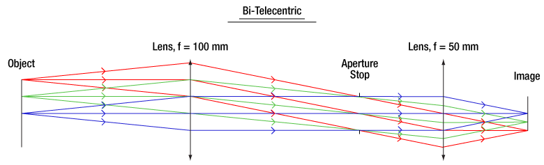
両側テレセントリックレンズの場合、前側と後側焦点面が重なる位置に開口絞りが配置され、入射瞳と射出瞳が共に無限遠になるように設計されています。両側テレセントリックレンズの倍率は像ならびに物体の位置に影響されることはありません。当社のテレセントリックレンズはすべて両側レンズの設計となっております。図3は、テレセントリックレンズを通る光線の追跡例で、主光線がどのようにシステムを透過するか示しています。
Click to Enlarge
図3: 両側テレセントリックレンズシステムの光線追跡 主光線(各色の中心光線)がレンズの物体側・像面側の光軸に対して平行なので、物体までの距離にかかわらずレンズの倍率は一定であることを意味します。
標準的なレンズ
標準的なレンズでは入射瞳と射出瞳は無限遠にはないため、主光線が光軸に対して平行にはなりません。この場合、レンズの倍率は物体までの距離ならびに視野範囲での位置によって決まります。図4は、標準レンズの光線追跡例です。主光線が像面ならびに物体側の光軸に対して斜めになっています。図3ならびに図4のレンズはともに同じ仕様のレンズを使用しています。しかし、開口絞りの位置に相違があります。

Click to Enlarge
図4: 標準レンズシステムの光線追跡 主光線(各色の中心光線)がレンズの物体側・像面側両方の光軸に対して平行ではありません。つまり物体までの距離によってレンズの倍率が変化することを意味します。
イメージ例
図5はテレセントリックレンズで撮像した写真、図6は、標準的なレンズで撮像した写真です。テレセントリックレンズで撮像したイメージでは、2つのネジが光軸に沿って約45 mm離れているのにもかかわらず、同じ高さに見えます。従来のイメージングシステムにおいては、この2つのネジの高さは異なるように見えるため、寸法の測定結果が正確ではない場合があります。両側テレセントリックレンズを用いたマシンビジョンシステムでは、寸法の計測において優位です。こちらのレンズは例えば当社のマルチセンサービデオ測定システムに組み込むことが可能です。

Click to Enlarge
図5: 0.128倍率のテレセントリックレンズMVTC23013(旧製品)で撮像した2つのキャップスクリュ。同じサイズのものが同じ物体面にあるように見えますが、実際は光軸に沿って約45 mm離れています。

Click to Enlarge
図6: カメラレンズMVL7000(旧製品)で撮像した同規格のキャップスクリュ。MVL7002は同様の性能を示します。画像では、離れているキャップスクリュの投影誤差によって正確な高さの寸法が得られません。
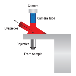
カメラで画像を表示する場合、システム倍率は対物レンズの倍率とカメラチューブの倍率の積です。三眼鏡筒で画像を表示する時のシステム倍率は、対物レンズの倍率と接眼レンズの倍率の積です。

| Manufacturer | Tube Lens Focal Length |
|---|---|
| Leica | f = 200 mm |
| Mitutoyo | f = 200 mm |
| Nikon | f = 200 mm |
| Olympus | f = 180 mm |
| Thorlabs | f = 200 mm |
| Zeiss | f = 165 mm |
倍率と試料領域の計算方法
倍率
システムの倍率はシステム内の各光学素子の倍率の積で求めます。倍率のある光学素子には右図の通り、対物レンズ、カメラチューブ、そして三眼鏡筒の接眼レンズが含まれます。なお、各製品仕様に記載されている倍率は通常、すべて同じメーカの光学素子を使用した時のみ有効であることにご留意ください。同じメーカの光学素子を使用していない場合、システムの倍率は下記の通り、まず対物レンズの有効倍率を求めたあと算出する必要があります。
下記の例をお手持ちの顕微鏡に応用する場合には、上のMagnification and FOV Calculator(赤いボタンをクリック)をダウンロードしてご使用ください。こちらの計算用エクセルファイルはマクロを使用したスプレッドシートになっています。計算を行う際はマクロを有効にする必要があります。マクロを有効にするには、ファイルを開いて、上部にある黄色いメッセージバー上の「編集を有効にする」ボタンをクリックしてください。
例1:カメラの倍率
試料をカメラでイメージングする場合、イメージは対物レンズとカメラチューブによって拡大されます。倍率が20倍のNikon製対物レンズと倍率が0.75倍のNikon製カメラチューブを使用している場合、カメラの倍率は20倍 × 0.75倍 = 15倍となります。
例2:三眼鏡筒の倍率
三眼鏡筒を通して試料をイメージングする場合、イメージは対物レンズの倍率と三眼鏡筒内の接眼レンズによって拡大されます。倍率が20倍のNikon製対物レンズと接眼レンズの倍率が10倍のNikon製三眼鏡筒を使用している場合、接眼レンズでの倍率は20倍 × 10倍 = 200倍となります。なお、右図のように接眼レンズでの像はカメラチューブを通りません。
メーカが異なる対物レンズと顕微鏡を使用する場合
倍率は根源的な値ではなく、特定のチューブレンズの焦点距離を推定して計算し、導き出す値です。右の表のように各顕微鏡メーカはチューブレンズに様々な焦点距離を設定しています。そのため異なるメーカの光学素子を組み合わせる場合、システムの倍率を算出するには対物レンズの有効倍率を計算する必要があります。
対物レンズの有効倍率は式1で求められます。
 | (Eq. 1) |
ここでDesign Magnificationは対物レンズに印字されている倍率、fTube Lens in Microscopeは使用する顕微鏡内のチューブレンズの焦点距離、fDesign Tube Lens of ObjectiveはDesign Magnificationを算出するために対物レンズのメーカが使用したチューブレンズの焦点距離です。焦点距離は右表に記載されています。
Leica、Mitutoyo、Nikonならびに当社ではチューブレンズの焦点距離は同じです。これらのメーカの光学素子を組み合わせた場合、倍率の変換は必要ありません。対物レンズの有効倍率が算出されたら、上記のようにシステムの倍率が計算できます。
例3:三眼鏡筒の倍率(異なるメーカを使用)
三眼鏡筒を通して試料をイメージングする場合、イメージは対物レンズの倍率と三眼鏡筒内の接眼レンズによって拡大されます。この例では倍率が20倍のOlympus製対物レンズと接眼レンズの倍率が10倍のNikon製三眼鏡筒を使用します。
式1と右の表によりNikon製顕微鏡内のOlympus製対物レンズの有効倍率を下記の通り計算しました。
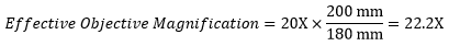 |
Olympus製対物レンズの有効倍率は22.2倍で、三眼鏡筒の接眼レンズの倍率は10倍なので、接眼レンズでの倍率は、22.2倍 × 10倍 = 222倍となります。
カメラでイメージングする試料領域
試料をカメラでイメージングする場合、試料領域の寸法はカメラセンサの寸法とシステム倍率を使用して下の式2で求められます。
 | (Eq. 2) |
カメラセンサの寸法はメーカが提供しています。またシステム倍率は対物レンズの倍率とカメラチューブの倍率の積です(例1をご参照ください)。必要に応じ、対物レンズの倍率を例3のように調整します。
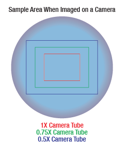
倍率が高くなればなるほど分解能も向上しますが、視野は狭くなります。倍率と視野の関係性については右の図でご覧いただけます。
例4:試料領域
当社のサイエンティフィックカメラ1501M-USB(旧製品)内のカメラセンサの寸法は8.98 mm × 6.71 mmです。このカメラを例1のNikon製対物レンズと三眼鏡筒に使用した場合、システム倍率は15倍となります。イメージングの領域は下記の通りになります。
 |
試料領域例
下のマウス腎臓の画像はすべて同じ対物レンズとカメラを使用して取得しました。ただし、カメラチューブのみ違う製品を使用しています。左から右の画像にいくにつれカメラチューブの倍率が下がっていますが、視野が広くなる分、細部も小さくなり見にくくなることが分かります。


分解能のチュートリアル
多くのイメージングにおいて、対物レンズの分解能は重要なパラメータです。このチュートリアルでは、対物レンズの分解能を定義するために使用されるさまざまな約束事について説明します。当社のサイトに掲載しているすべてのイメージング用対物レンズには、レイリー分解能の理論値を示しています。ここに示すそれ以外の基準に基づく記述方法は、情報提供の目的で提示しています。
分解能
対物レンズの分解能は、物体の近接した構造を識別する性能を表します。これは多くの場合、2つの点光源で構成される物体を想定し、これらの2つの点光源を分解できる最小間隔を求めることによって理論的に定量化します。点光源をイメージングしてみると、単体の明るい点となることはなく、回折の影響を受けて幅の広い強度プロファイルとして現れます。このプロファイルはエアリーディスクとして知られ、強度の高い中央のピークと、それを囲む強度の低いリングから構成されます。そのため、2つの互いに近接する点光源から生成されるイメージは、2つの重なり合うエアリーディスクプロファイルから構成されることになります。したがって、対物レンズの分解能は2つのプロファイルを一意的に識別できる最小間隔によって決めることができます。どのような状態であれば2つのプロファイルが分解されたとするのかという点について、基本的な基準はありません。しかし、実際に使用されている基準は幾つかあります。顕微鏡イメージングの分野で最も一般的に使用されている基準としては、レイリーの基準とアッベの基準の2つがあります。その他の基準としては、天文学の分野でより一般的に用いられているスパローの基準があります。
レイリーの基準
レイリーの基準では、一方の強度プロファイルの最初の極小値の位置が、もう一方の強度プロファイルの最大値の位置と一致したときに、2つの重なり合うエアリーディスクプロファイルが分解されたとします[1]。エアリーディスクの最初の強度の極小値は、中心の最大値から半径1.22λf/Dの位置に生じることを示すことができます。ここで、λは光の波長、fは対物レンズの焦点距離、Dは入射瞳の直径です。したがって、開口数(NA = 0.5*D/f)を用いて、レイリー分解能は次の式で表されます。
rR = 0.61λ/NA
レイリー分解能に等しい距離だけ離れた2つのエアリーディスクの理想的なイメージを左下に示します。光源はインコヒーレント光源であると仮定しています。この図の2つの最大値を通る水平な線に沿って、その強度分布をグラフ化すると右側の図が得られます。この強度プロファイルの図における垂直の点線により、一方のエアリーディスクの最大値の位置と、もう一方のエアリーディスクの最初の極小値の位置が一致していることが分かります。2つの最大値の間には極小値があり、それにより2つの白いピークの間には灰色の領域が現れています。
 Click to Enlarge
左:2つの点光源がレイリー分解能によって分離されたとき、それらは分解されたとみなします。2つの白いピークの間に灰色の領域がはっきりと見えます。
上:垂直の点線により、一方の強度プロファイルの最大値の位置が、もう一方の強度プロファイルの最初の極小値の位置と一致していることが分かります。

当社では、ウェブサイトに掲載しているすべてのイメージング用対物レンズについて、そのレイリー分解能の理論値を個別の製品説明ページでご提示しています。
アッベの基準
アッベの理論では、画像形成を回折の二重プロセスとして表現します[2]。そのフレームワークでは、2つの構造が距離dだけ離れているとき、それらを分解するには少なくとも0次と1次の両方の回折光が対物レンズの開口部を通過する必要があるとします。1次回折光はsin(θ1) = λ/dで表される角度θ1の方向に現れるため、分解可能な最小の物体間距離、すなわち対物レンズの分解能はd = λ/n*sin(α)で与えられます。ここで、αは対物レンズの半開口角、係数nはイメージング媒体の屈折率です。この結果は、実際の限界に対して2倍の過大評価をしています。理由は、0次光とともに対物レンズを通過しなければならない1次光は少なくとも1つあればよいわけですが、ここでは両方の1次光を通過させているためです。上記の結果を2で除し、さらに開口数の定義(NA = n*sin(α))を使用することで、有名なアッベの分解能限界が得られます。
rA = 0.5λ/NA
下の画像は、アッベの分解能限界で分離された2つのエアリーディスクを表しています。レイリー限界と比較して、原点における強度の減少を識別するのは大分困難になります。右側の強度分布図を見ると、中心の強度の減少はわずか2%です。
 Click to Enlarge
左:アッベの分解能限界によって分離された2つの点光源 最大値と中央の極小値の間のコントラストは観察可能ではありますが、レイリー限界と比較するとはるかに弱くなっています。
上:このグラフでは2つの最大値の間に小さな強度の減少が見られます。

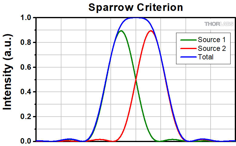
スパローの基準
2つの点光源の間の距離がレイリーまたはアッベの分解能基準に対応する場合、重ね合わせられた強度プロファイルにおける2つの最大値の間の原点に極小値が見えます。そういった意味では、これらの評価基準では2つの点光源を分解することができています。しかし、点光源間の距離がアッベの分解能限界を超えてさらに小さくなると、2つの独立した最大値は1つの中央の最大値に一体化され、2つの光源からの寄与を個々に分解することができなくなります。スパローの基準では、中央の極小値が中央の最大値に変化したときに分解能限界に達したとします。
スパローの分解能限界では、重ね合わせられた強度プロファイルの中心は平坦になります。これは、位置に関する微分係数が原点でゼロになることを意味します。しかし、原点でのこの1次微分係数は、重ね合わせられた強度プロファイルの極小値または最大値であるため、常にゼロです(厳密に言えば、これは2つの光源の強度が等しい場合にのみ当てはまります)。従って、原点の強度が極小値から最大値に変化するときにスパローの分解能限界に到達したことになるため、このときに2次微分係数の符号が正から負に変化する必要があります。このようにスパローの基準は2次微分係数に課される条件となり、2次微分係数がゼロのときに分解能限界に到達することになります[3]。 この条件を2つのエアリーディスクが重ね合わせられた強度プロファイルに適用すると、スパロー分解能が次のように得られます。
rS = 0.47λ/NA
左下の画像は、スパローの分解能限界の距離に置かれた2つのエアリーディスクのイメージを示しています。上記のように2つのピークの間では強度が一定であり、原点での強度のくぼみはありません。右側のグラフでは、原点付近で強度が一定であることを確認できます。
 Click to Enlarge
左:スパローの分解能限界によって分離された2つのエアリーディスクのプロファイル レイリーやアッベの限界とは異なり、原点で強度は減少しません。
上:スパローの分解能限界では、重ね合わせられた強度分布は原点付近で一定になります。ここではスケールが1に規格化されています。

参考文献
[1] Eugene Hecht, "Optics," 4th Ed., Addison-Wesley (2002)
[2] S.G. Lipson, H. Lipson, and D.S. Tannhauser, "Optical Physics," 3rd Ed., Cambridge University Press (1995)
[3] C.M. Sparrow, "On Spectroscopic Resolving Power," Astrophys. J. 44, 76-87 (1916)

Click to Enlarge
Old Objective Packaging

Click to Enlarge
New Objective Packaging
Smart Pack Goals
- Reduce Weight of Packaging
- Increase Usage of Recyclable Materials
- Improve Packing Integrity
- Decrease Shipping Costs
Thorlabs' Smart Pack Initiative is aimed at minimizing waste while providing adequate protection for our products. By eliminating any unnecessary packaging, implementing design changes, and utilizing eco-friendly materials, this initiative seeks to reduce the environmental impact of our product packaging.
The new super achromatic microscope objective packaging is made from over 60% recycled paper products and weighs 25.44 g less than the old packaging. The transition from foam and non-recycled cardboard to recycled paper products results in a 68.05% reduction in the amount of CO2 produced per kg of packing materials. All products on this page have transitioned, or are in the process of transitioning to recycled paper.
As we move through our product line, we will indicate re-engineered, eco-friendly packaging with our Smart Pack logo, which can be seen in the image to the right.
| Posted Comments: | |
user
(posted 2024-07-04 12:22:40.993) Would any of these objectives be cryo-compatible? cdolbashian
(posted 2024-07-19 02:58:35.0) Thank you for reaching out to us with this inquiry. We discussed your application, and the fact that you need to use these objectives in a 4 Kelvin environment. Unfortunately, as these were not designed for this environment, it is unlikely that you could use one of these scopes to the specced performance. I have contacted you directly to discuss possible alternatives. Hannes Kamin
(posted 2024-06-19 13:51:17.263) Hi Thorlabs Team,
can the TL10X-2P be used with cleared samples? I want to dipp in into clearing media with high refractive index. Is the objective resistant to ECI or BABB (Ethyl cinnamate or Benzyl / Alcohol / Benyl Benzoat) when dipping into that media?
Thank you very much cdolbashian
(posted 2024-06-28 11:32:27.0) Thank you for reaching out to us with these inquiries. This objective can indeed be used with cleared samples. When considering dipping media, we would advise only non corrosive immersion oils or water. KYLE LILLIS
(posted 2024-02-09 15:35:00.233) We recently purchased the TL10X-2P for in vivo imaging. Can you tell me how you recommend sterilizing this objective? I assume it can't be autoclaved? How about EtO? cdolbashian
(posted 2024-02-19 10:51:55.0) Thank you for reaching out to us with this usage inquiry. We would not recommend autoclaving this component. We would recommend regular, normal cleaning immediately after each use, The lens paper should be immersed in an appropriate solvent to remove any oils used and you should clean the lens without endangering it. We advise using blended alcohol, anhydrous alcohol, or a lens-cleaning solution. Xindong Song
(posted 2021-02-25 16:31:18.73) Hi Thorlabs, we are very interested in getting the TL10X-2P objective for in vivo 2p imaging. But before we place the order, we wonder if we can talk to any other customers about their experience with the objective. Thank you. YLohia
(posted 2021-03-05 10:00:19.0) Hello, thank you for contacting Thorlabs. Unfortunately, we cannot share customer information due to privacy concerns. That being said, you can look through publicly available literature for mentions of this lens and contact the authors of those papers. For example, here is a Google Scholar search with a few relevant results: https://scholar.google.com/scholar?hl=en&as_sdt=0%2C31&q=TL10X-2P&btnG= Michael Orger
(posted 2020-11-06 06:51:53.37) Hi, Can you define Forward and Reverse for the TL10X-2P zemax black box files? It seems to be the opposite of what I expect, but I am not sure if it is a misunderstanding on my part. Thanks! asundararaj
(posted 2020-11-10 09:40:01.0) Thank you for contacting Thorlabs. Forward is typically defined as sending a collimated light into the objective, and the reverse is defined as sample being on the object side. Forward is always from collimation to focus. Gabriel Martins
(posted 2019-07-17 06:54:01.707) good morning,
do you have information on how the 10x performs with cleared samples, ie, samples in medium with refractive index of ~1.52?
Would it be possible to test the objective with our samples?
Thanks in advance,
Gaby asundararaj
(posted 2019-07-23 10:08:15.0) Thank you for contacting Thorlabs. Yes, the TL10X-2P objective can be used with cleared samples. You would need to set the spherical collar to the appropriate setting. You can find a procedure for calculating the correct setting in the Correction Collar tab of this page. I have contacted you directly about being able to offer a loan unit. Denis Pristinski
(posted 2019-07-12 12:53:38.397) Is Zemax black box model coming for TL10X-2P? YLohia
(posted 2019-07-16 09:02:38.0) Hello, thank you for contacting Thorlabs. The Zemax model for this can be found here : https://www.thorlabs.com/_sd.cfm?fileName=TTN142896-S02.zar&partNumber=TL10X-2P a.scagliola2
(posted 2018-11-05 12:38:56.0) Do you have a model of the objective with the principal planes? nbayconich
(posted 2019-03-04 01:17:21.0) Thank you for contacting Thorlabs. The principal plane will be located approximately 16mm in front of the objective lens or 16mm after the m25 x0.75 threading. I will reach out to you directly with more information. a.andreski
(posted 2017-11-28 15:40:24.44) Do these objectives have a flat field of view (are they plan)?
If I use the TL2X-SAP with a TTL100A tubelens, what is the maximum object field of view that is possible without abberations?
Thanks. tfrisch
(posted 2017-12-15 04:35:36.0) Hello, thank you for contacting Thorlabs. The Field of View will be flat, yes. TL2X-SAP will be diffraction limited over its full Field of View. I will reach out to you directly with details on the Strehl ratio. ludoangot
(posted 2016-11-07 15:31:29.6) Which tube lens do you recommend to match the extended transmission of these microscope lenses in the deep blue / UV (your recent TTL200 is for 400 to 700nm)? tfrisch
(posted 2016-11-10 10:24:31.0) Hello, thank you for contacting Thorlabs. I would typically recommend TTL200 which performs well over the range of TL2X-SAP and TL4X-SAP. You can see some performance graphs here: https://www.thorlabs.us/newgrouppage9.cfm?objectgroup_id=5834&tabname=Graphs |

 ズーム
ズームTL10X-2P Super Apochromatic Microscope Objective
- Dry Objectives Ideal for Two-Photon Microscopy
- Correction Collar Enables Use with Samples in a Variety of Media
- M32 x 0.75 Threading
The TL15X-2P Plan Apochromatic Improved Visible (APO VIS+) and TL10X-2P Super Apochromatic Objectives combine the diffraction limited axial color performance at visible wavelengths of our other objectives with excellent transmission out to 1300 nm, making these objectives ideal for multiphoton imaging applications (see the Graphs tab for details). For more information about how these objective classes are defined, see the Objective Tutorial tab. The 15X objective features a high 0.70 NA for collecting two-photon fluorescence signals and a working distance of 2.6 mm. The 10X objective combines a 0.50 NA with a long 7.77 mm working distance, providing ample space for equipment to manipulate the sample. A correction collar on each objective allows adjustment for spherical aberrations introduced by imaging through aqueous solutions or thick cover glasses, without the need for water dipping or oil immersion (see the Correction Collar tab). The TL15X-2P objective additionally features a locking mechanism to fix the correction collar in place for improved repeatability.
 Click to Enlarge
Click Here for Full-Size Image
Wild Type Mouse Brain Section (30 µm) Tagged with DAPI (405 nm) and Alexa 488 Anti-Neurofilament Taken with TL10X-2P Objective (Courtesy of Lynne Holtzclaw of the National Institutes of Health)
Note that for best performance, the front focal plane of your system's tube lens should be placed at the objective's aperture stop. For most objectives, this stop coincides with the back element at the shoulder. The aperture stops in Item #s TL10X-2P and TL15X-2P are located 42.0 mm and 52.2 mm from their shoulders, respectively. Without filling this stop, vignetting may occur. For example, Thorlabs' TTL200MP tube lens' focal plane is located at 228 mm from the shoulder of the tube lens. Therefore, the physical separation between the front element of the tube lens and the shoulders of the TL10X-2P and TL15X-2P objectives should be 186 mm and 175.8 mm, respectively. These examples are illustrated in the alignment diagrams that can be viewed by clicking on the blue info icons (![]() ) in the table below.
) in the table below.
Due to the large outer diameter of this objective's housing, it may not mate properly with nosepieces that have recessed M32 x 0.75 internal threads such as Item #s CSN200 and CSN210. In this case, the M32M32S brass microscope adapter has external and internal M32 x 0.75 threads that can provide additional clearance between the edge of the objective housing and the mount.
The full-size download of the mouse brain image to the lower right should be viewed using ThorCam, ImageJ, or other scientific imaging software. It may not be displayed correctly in general-purpose image viewers.
| Key Specifications | |||||||||||||||
|---|---|---|---|---|---|---|---|---|---|---|---|---|---|---|---|
| Item # | AR Coating Wavelength Range |
Mag. | Numerical Aperture |
Working Distance |
Parfocal Length |
Cover Glass Thickness |
Threading | Alignment Diagram |
|||||||
| TL15X-2P | 400 - 1300 nm | 15X | 0.70 | 2.6 mma | 75.0 mm | 0 - 2.8 mm | M32 x 0.75 |  |
|||||||
| TL10X-2P | 10X | 0.50 | 7.77 mm | 95.0 mm | 0 - 2.6 mm |  |
|||||||||
| Recommended Microscopy Techniques | ||||||
|---|---|---|---|---|---|---|
| Confocal | Two-Photon | Brightfield | Darkfield | Dodt | DIC | Fluorescence |
| - | ||||||

 ズーム
ズーム- 低光量およびワイドフィールド観察に適した高NAレンズ
- M25 x 0.75ネジ
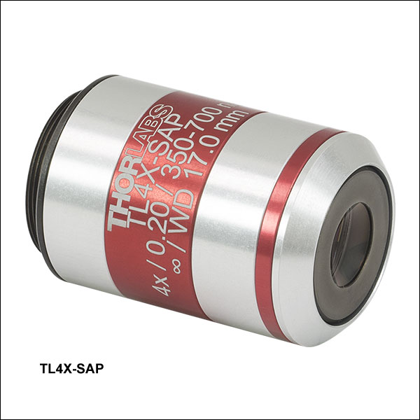
こちらの汎用の対物レンズは、400 nm~750 nmにおいて軸上色収差を回折限界まで補正します。対物レンズは様々なイメージング手法において優れた性能を発揮し、試料の広い範囲を観察するのに便利です。対物レンズTL2X-SAPの視野はØ11 mmと大きく、かつ視野全体にわたり細部を捉えることができます(図1と2参照)。TLX4X-SAPの倍率は4倍で、倍率2倍の対物レンズよりも分解能が高く、視野はØ5.5 mmですが試料内の一定の範囲を捉えることができます(下の図3および図4参照)。どちらの対物レンズも作動距離が長いため、マイクロマニピュレータを使用するのに十分なスペースを確保できます。
下記画像はThorCam、ImageJほかのサイエンティフィックイメージングソフトウェアからご覧いただけます。一般的な画像ビューアをご使用の場合、正しく表示されない場合があります。
 Click to Enlarge
フルサイズ画像はこちらをクリックしてご覧ください。
図1:対物レンズTL2X-SAP、白色照明、カラーカメラを使用して取得したゼブラフィッシュ胚の画像。ゼブラフィッシュの全長を捉えていますが、細部も見えています。
 Click for Details
フルサイズ画像はこちら をクリックしてご覧ください。
図2:対物レンズTL2X-SAPを用いて取得された日長石の画像。日長石の大部分を捉えながら、視野全体に渡り優れた分解能が得られています。画像ご提供:Stephen Challener氏
 Click to Enlarge
フルサイズ画像はこちらをクリックしてご覧ください。
図3:DICイメージングのセットアップで対物レンズTL4X-SAPとモノクロカメラを用いて取得した双子葉植物の花芽の画像
 Click to Enlarge
| Key Specifications | ||||||||||||||
|---|---|---|---|---|---|---|---|---|---|---|---|---|---|---|
| Item # | AR Coating Wavelength Range | Mag. | Numerical Aperture | Working Distance | Parfocal Length | Cover Glass Thickness | Threading | Recommended Microscopy Techniques | ||||||
| Confocal | Two-Photon | Brightfield | Darkfield | Dodt | DIC | Fluorescence | ||||||||
| TL4X-SAP | 350 - 700 nm | 4X | 0.20 | 17.0 mm | 60.0 mm | 0 - 0.5 mm | M25 x 0.75 | - | ||||||
| TL2X-SAP | 350 - 700 nm | 2X | 0.10 | 56.3 mm | 95.0 mm | 0 - 0.5 mm | M25 x 0.75 | - | ||||||

 ズーム
ズーム Click to Enlarge
フルサイズ画像はこちらをクリックしてご覧ください。
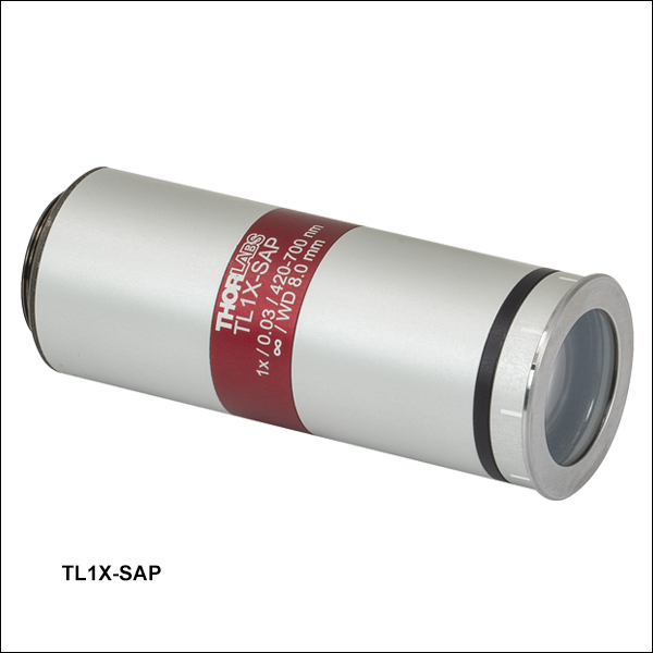
10 kΩ抵抗とダイオードを表面実装した回路基板の画像。リングライトFRI61F50の反射照明、カラーカメラ、および対物レンズTL1X-SAPを使用しています。 対物レンズがテレセントリックレンズとして設計されているため、像の深さに関わらず倍率が一定に保たれます。
- マシンビジョンに適した対物レンズ
- テレセントリックレンズとして設計、後方反射低減用の波長板付き
- M25 x 0.75ネジ

Click to Enlarge
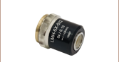
対物レンズTL1X-SAPには取り外し可能な波長板が付属しており、これを対物レンズの筒の先に磁石で取り付けることができます。
スーパーアポクロマート対物レンズTL1X-SAPは、440 nm~700 nmにおいて軸上色収差を回折限界まで補正します。テレセントリックレンズとして設計されているため、視野内の物体の距離や位置に関わらず倍率は一定です。詳細は「テレセントリックレンズチュートリアル」をご覧ください。こちらの対物レンズの視野はØ22 mmで、マシンビジョン用に適しています。 付属の取り外し可能な波長板を落射照明系で使用すると、後方反射を抑えてコントラストを向上させることができます。 波長板は対物レンズ筐体内の磁石で固定されます。倍率1倍の対物レンズ筐体上の白いマークと波長板上の黒い点は、波長板を回転させるときのガイドとなります。
右の回路基板のフルサイズ画像はThorCam、ImageJ、またはその他のサイエンティフィックイメージング用ソフトウェアでご覧ください。一般的なイメージビュワーではこれらのイメージは正しく表示されない場合があります。
| Key Specifications | ||||||||||||||
|---|---|---|---|---|---|---|---|---|---|---|---|---|---|---|
| Item # | AR Coating Wavelength Range | Mag. | Numerical Aperture | Working Distance | Parfocal Length | Cover Glass Thickness | Threading | Recommended Microscopy Techniques | ||||||
| Confocal | Two-Photon | Brightfield | Darkfield | Dodt | DIC | Fluorescence | ||||||||
| TL1X-SAP | 420 - 700 nm | 1X | 0.03 | 8.0 mma | 95.0 mma | 0 - 0.5 mm | M25 x 0.75 | - | ||||||