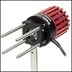
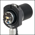
マウント付きLED
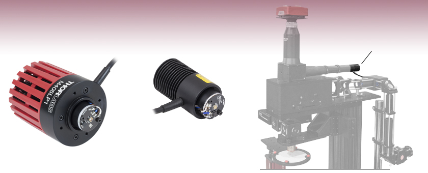
- UV, Visible, IR, and Mid-IR Models Available
- Optimized Heat Management Results in Stable Output
- Internal SM1 (1.035"-40) Threading
- Collimation Adapters Available Separately
M405LP1
405 nm,
1200 mW Minimum Output Power
M505L4
505 nm,
400 mW Minimum Output Power
Mounted LED used as a Light Source for a DIY Cerna® Microscope

Please Wait
| 各種資料のご案内 | |
|---|---|
| 仕様や図面等の各製品の情報は、仕様表内のInfo欄の青いアイコンから取得可能です。 | |
| 型番横の赤い資料アイコンでは、各種技術資料を提供しています。 | |
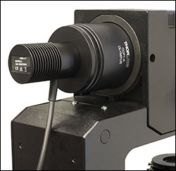
Click to Enlarge
Olympus製顕微鏡用の透過照明光源として使用されているLED MWWHL4と顕微鏡用コリメートアダプタCOP1-A
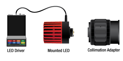
マウント付きLEDを動作させるにはLEDドライバが必要です。LEDから出射される発散ビームをコリメートするには、コリメートアダプタ(別売り)を使用します。適切なLEDドライバについては下の表をご参照ください。各LEDに対して必要なコリメートアダプタは、下の青いInfoアイコン(
マウント付きLEDの特長
- 波長範囲:265 nm~5200 nm(右の表をご覧ください)
- 白色、広帯域、デュアルピークのLEDもご用意
- 内蔵メモリにLED動作パラメータを保存
- 熱特性を最適化して安定した出力光パワーを実現
- 顕微鏡とSMネジに対応したコリメートアダプタをご用意
- カスタム仕様の電源用に4ピンメス型コネクタもご用意(別売り)
コリメータ無しのマウント付きLEDでは、深さ6 mmのSM1内ネジを有するヒートシンクの端面にLEDが1つ取り付けられています。Ø30.5 mmのヒートシンクの付いたLEDの外径はSM1レンズチューブと同じであるため、30 mmケージシステムにも取り付けられます。動作中の発熱量が大きい一部のLEDは、より大型のヒートシンクに取り付けられています。この大型のヒートシンクは通気口の付いたØ57.0 mmのプラスチック製筐体に納められていますが、前面にある4つの#4-40タップ穴で 30 mmケージシステムに組み込むことができます。
各LEDにはそれぞれのLEDに関する情報(電流リミット値、波長、順方向電圧など)を保存するEEPROMが付いています。当社のLEDドライバDC2200、DC4100またはDC4104を使用する場合は、これらの情報をスマートセーフティ機能でご利用いただくことができます。
マウント付きLEDは熱的な安定性が優れているため、LEDの温度上昇に伴って光出力が低下するという問題は生じません。詳細は「安定性」タブをご参照ください。
なお、マウント付きLEDは家庭用照明としては作られておりませんのでご注意ください。
LED出力光のコリメート
当社の調整機能付きコリメートアダプタを用いると、Ø25 mm(Ø1インチ)レンズは最大11 mm、Ø50 mm(Ø2インチ)レンズは最大20 mmの移動が可能です。各調整機能付きコリメートアダプタにはSM2内ネジ付きアダプタが付属しているので、LEDを当社のØ50 mm~Ø50.8 mm(Ø2インチ)光学素子用レンズチューブなどのSM2ネジ付きコンポーネントに簡単に取り付けることができます。このアダプタには、ARコーティング付き非球面コンデンサーレンズの付いたタイプと付いていないタイプがございます。
また、ARコーティング付き非球面レンズを組み込んだ顕微鏡用コリメートアダプタもご用意しております。これらのアダプタは、Leica DMI、Nikon Eclipse Ti、Olympus IX/BX、Zeiss Axioskopなどの一部の顕微鏡の落射照明ポートにも接続できます。当社ではマウント付きLEDにあらかじめ顕微鏡用コリメートアダプタを取り付けた製品もご用意しています。
当社の多くのLEDについて出力光をコリメートする方法をご提案しています。詳細は下の青いInfoアイコン(![]() )をクリックしてご覧ください。「コリメーション」タブでは、LEDのコリメート方法について詳細がご覧いただけます。
)をクリックしてご覧ください。「コリメーション」タブでは、LEDのコリメート方法について詳細がご覧いただけます。
ドライバ
当社では、こちらのLEDに対応するドライバとしてLEDD1B、UPLED、DC40、DC2200、DC4100、DC4104の6種類をご用意しています(DC4100とDC4104にはDC4100-HUBが必要です)。適合するドライバについては下の表、ドライバの仕様については「LEDドライバ」のタブをご覧ください。ドライバUPLED、DC40、DC2200、DC4100、DC4104は接続されたLEDのEEPROMから電流のリミット値を読み取り、最大電流値を自動的に設定してLEDを保護することができます。
マルチLED光源
当社のマウント付きLEDに当社の他の部品を組み合わせて、カスタマイズ可能なマルチLED光源の構築が可能です。例えば、当社の汎用的なSM1レンズチューブシステムや30 mmケージシステムを用いて、そのような光源を組み立てることができます。詳細な型番のリストや構築方法等については「マルチLED光源」タブをご覧ください。
自由に設定ができる統合型の4波長高出力LED光源もご提供しています。
出力光パワーの比較
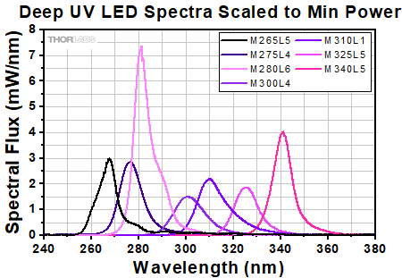
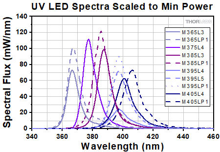
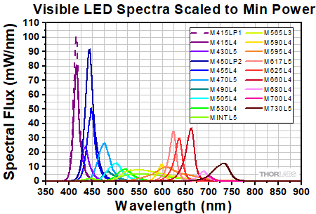
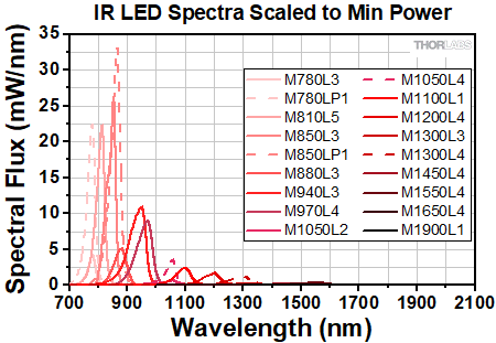
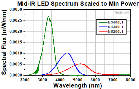
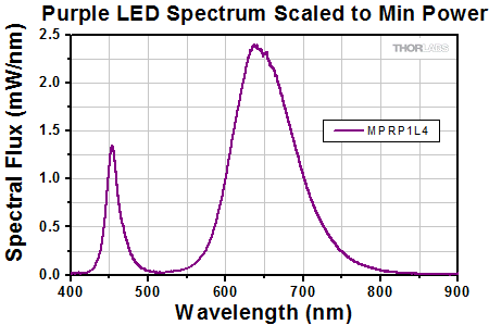
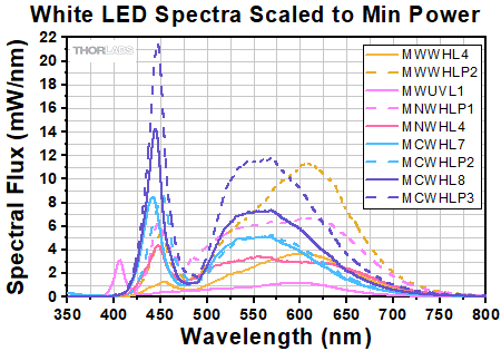
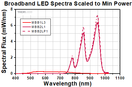
個々のLEDから出力される実際の光スペクトルや全光パワーは、製造工程や、温度や電流などの動作パラメータによって異なります。適切なLEDをお選びいただくために、出力光パワーの典型値と最低値を明記しています。各マウント付きLEDは、最大電流において少なくとも最低値として明記された光パワーを出力します。公称波長の異なるLEDの出力光パワーを互いに比較できるよう、下のグラフのスペクトルは各LEDの最低値の光パワーでスケーリングされています。これらのデータは代表例です。すべてのマウント済みLEDのスペクトルデータをまとめたエクセルファイル(規格化データおよびスケーリングデータ)はグラフ下のリンクからダウンロードいただけます。
Click to Enlarge
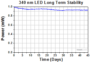
当社の340 nmマウント付きLEDの典型的な寿命は3,000時間以上です。45日後の試験対象ユニットは初期出力パワーの90%以上を持続しています。
LEDの寿命および長期的なパワー安定性
LEDの特性の1つとして、時間の経過と共にパワーが自然に低下することがあげられます。ほとんどの場合、パワーは緩やかに低下しますが、急速な低下や完全な停止、あるいは故障が突然起こることもあります。LEDの寿命は、LEDの種類ごとに規定されたある割合のLEDが、あるパワーレベル以下に低下するまでの時間で定義されます。寿命測定のパラメータはBXX/LYYで表され、ここでXXはその種類のLEDで寿命が過ぎた後の出力パワーが規定値のYY%以下になるLEDの割合を示します。当社では、LEDの寿命をB50/L50で表しますが、これはその型番のLEDのうち50%のLEDの光パワーが規定の寿命がきた時に初期値の50%以下に低下するという意味です。例えば、定格出力パワー150 mWのLED100個のうち、50個の出力パワーが規定の寿命を過ぎたときに75 mW以下に低下するということです。
右のグラフは、340 nmマウント付きLEDについて45日間にわたる長期安定性試験を行った際のデータ例です。340 nmマウント付きLEDの典型的な寿命は3,000時間(約125日以上)となっています。LEDをONにした後にパワーがわずかに低下しているのは、動作開始から数分間の典型的な動きです。これはLEDが温まり、熱的に安定するまでの時間に相当します。グラフは1個のLEDに関する性能を示しています。LEDの性能は仕様の範囲内で単体ごとに異なりますのでご注意ください。
最適化された温度管理
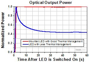
こちらのマウント付きLEDの放熱は安定な出力のために最適化されています。ヒートシンクはLEDマウントに直接取付けられていて、熱的接触は適切な状態になっています。これにより、LED接合面の温度の上昇によって生じる光出力パワーの減衰を最小に抑えることができます(左側のグラフをご参照ください)。
Video Insight(How-to動画):LEDからの出力光をコリメートする方法
LEDやその他の寸法の大きなインコヒーレント光源からの光をコリメートするのは、意外にも難しい作業になる場合があります。エミッタのサイズ、コリメートレンズの焦点距離と開口数(NA)など、それらのすべてがコリメートされたビームの特性に影響します。また、レンズが適切な位置にあることを見極めるのも難しい場合があります。動画では2種類のコリメート方法をご紹介しています。さらに、NAと焦点距離の異なる2種類のレンズを使用して、レンズのNAを大きくするとLEDからより多くのパワーを集光できる代わりに、コリメート光が発散する割合も大きくなることを示しています。
LEDからの出力光をコリメートする2種類の方法
上記のVideo Insight(How-to動画)でご覧いただけるように、LEDの出力光を適切にコリメートするためには、選択したコリメートレンズとLED間の距離を調整する必要がある場合があります。コリメート光は光路の局所的な領域でしか得られません。このコリメートされた領域では、ビームの発散は最小限に抑制され、どの位置でも収斂することはありません(比較については下の写真をご参照ください)。どのようなビームを用いても完全にコリメートすることはできず、コリメート光も一定の割合で徐々に発散します。LEDのようなインコヒーレントな光源では、エミッタのサイズが大きいほど発散の割合が大きくなります ここではコリメート光を得るための2つの方法についてご紹介します。
方法1:LEDを無限遠で結像させる
- LEDの電源を入れます。
- コリメートレンズから約30~60 cm離れた場所にビューイングスクリーンを置きます。
- コリメートレンズとLEDの距離を調整して、LED像をビューイングスクリーンに映し出します(下図A)。
- ビューイングスクリーンをLEDからさらに遠ざけます。
- スペースがある限りステップ3と4を繰り返します。
- ビューイングスクリーンをコリメートレンズから約30~60 cmの元の距離に戻すと、収斂しない均一なビームが見えるはずです。十分にコリメートされていれば、ビームは円形に近く(わずかに多角形の場合もあり)、LEDそのものの像がはっきり見える状態ではありません。画像Cは、コリメートされたビームの例です。
- コリメートレンズの最適な位置を見つけたら、コリメートレンズの位置を固定します。
注: スペースの制約により、この方法を有効に使えない場合があります。スペースが限られている場合は、方法2(下記)の方が有利な場合があります。
方法2:ビームの広がりを利用してコリメートレンズの位置を設定する
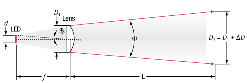
- コリメートレンズから距離Lの位置で予想されるビーム径(D2)を求めます。
Click to Enlarge
図1: コリメートレンズの後方のビームの予測される広がり。サイズdのLEDからの光は、直径D1、 焦点距離fのレンズで集光され、レンズ後方では発散角Φが生じます。レンズから距離 Lの位置でのビーム径はD2 = D1 + ΔDになります。
図1は、LEDから放射されてコリメートレンズを通過するビームの伝搬の様子を示しています。コリメートレンズ後方で予想されるビーム発散角(Φe)は、次の式で与えられます。

ここで、dはLEDの横方向の大きさ、fはコリメートレンズの焦点距離です。コリメートレンズから距離Lの位置で予想されるビーム径(D2)は、以下の式で計算できます。

ここで、

式1を式3に代入すると、ΔD=Ld/fとなり、次の式が得られます。

- LEDの電源を入れます。
- 距離Lの位置にビューイングスクリーンを置き、コリメートレンズの位置を調整してビューイングスクリーン上でビーム径が D2となるようにします。
- これがコリメートレンズの適切な位置ですので、コリメートレンズの位置を固定します。
下の表では、Ø25.4 mm(Ø1インチ)非球面コンデンサーレンズ(ACL2520U)を用いた時の、LEDごとの視野半角(Half Viewing Angle)の違いを例示しています。 一部のLEDについては、下のInfoアイコン( ![]() )をクリックして 「Collimation Adapter」タブをご覧いただくと、推奨されるコリメート用の光学システムを見ることができます。
)をクリックして 「Collimation Adapter」タブをご覧いただくと、推奨されるコリメート用の光学システムを見ることができます。
| Item # | Color | Nominal Wavelengtha | Calculated Lens to Emitter Distanceb | Half Viewing Anglec | ||
|---|---|---|---|---|---|---|
| +1 mm Out of Focusd | at Calculated Focusing Distance | -1 mm Out of Focusd | ||||
| M850L3 | IR | 850 nm | 13.8 mm | 3.29° | 3.10° | 3.93° |
| M940L3 | IR | 940 nm | 13.9 mm | 3.42° | 2.46° | 3.70° |

| Pin | Specification | Color |
|---|---|---|
| 1 | LED Anode | Brown |
| 2 | LED Cathode | White |
| 3 | EEPROM GND | Black |
| 4 | EEPROM IO | Blue |
ピン接続:オス型
右の図は、マウント付きLEDアセンブリのオス型コネクタを示しています。 これは、標準的なM8x1センサ円形コネクタです。 ピン1と2はLED接続用です。 ピン3と4はLEDに内蔵するEEPROMに使用されます。 当社以外のLEDドライバをご使用の場合、ピン1と2の接続は適切に行ってください。またEEPROMピンからLED駆動しないようご注意ください。
Click to Enlarge
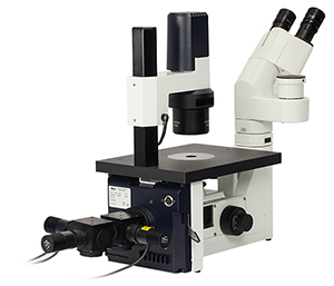
顕微鏡の照明ポートに接続されたマルチLED光源
カスタム仕様の顕微鏡照明用マルチLED光源
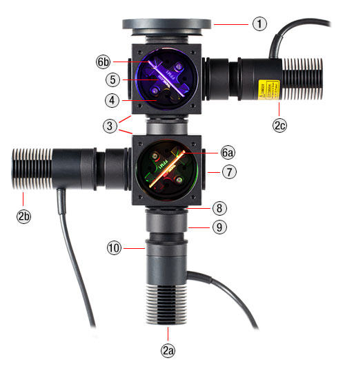
当社では下でご紹介しているマウント付きLEDを2台もしくは3台使用して、お客様の仕様に基づくマルチLED光源を組立てていただくのに必要なアイテムをご用意しております。 以下の構成例のように、光源は顕微鏡の照明ポートに用いられるように設計されています。 しかし、当社のSM1シリーズのレンズチューブや30 mmケージシステムを利用すれば、その他のアプリケーションにも組み込むことができます。 LED内蔵で、お客様が自由に設定できる4波長高出力LED光源もご提供可能です。
設計と構築
まず、光はレンズチューブに取り付けられたレンズによってコリメートします。 キネマティックケージキューブに取付けられたダイクロイックミラーが、複数のLEDからの出力を結合します。 マウント付きLEDは、小型のT-Cube LEDドライバLEDD1Bで駆動できます(電源は別売りです)。LEDドライバLEDD1Bを用いることで、各LEDの出力を個々に変調でき、最大1200 mAの電流を供給することができます。 LED光源は、最大定格電流を越えて駆動しないようご留意ください。
カスタム仕様の光源を設計する際は、下記掲載のマウント付きLEDと併せて、LEDの波長の中間に位置するカットオフ波長に対応するダイクロイックミラーもご用意ください。 適切なダイクロイックミラーを選べば、側面に取り付けたLEDからの反射光を反射し、光軸に沿った光を透過させます。 大部分のダイクロイックミラーは、「ロングパス」フィルタであることにご留意ください。つまり、カットオフ波長よりも長い波長の光を透過し、短い波長の光を反射します。 ロングパスフィルタを使用して3台以上のLEDの光を重ねるには、より長い波長のLEDを後ろから順番に重ねてください(下記参照)。 長い波長を反射し、短い波長を透過させる際にはショートパスフィルタをご使用いただけます。 下の3つの表で、適合するダイクロイックミラーとLEDの組み合わせのサンプルをご紹介しています。
各光源に適切なARコーティング付きの非球面コンデンサーレンズの選択も必要です。 光源を組立てる前に、マウント付き高出力LEDからの光をコリメートしてください。詳細は「コリメート」タブをご覧ください。 付属の固定リングSM1RRを用いてレンズチューブSM1V05内に非球面レンズを取り付ける際は、調整機能付きスパナレンチSPW801のご使用をお勧めします。 適切にコリメートされたLED光源からのビームは、ほぼ均一で、60 cmの距離では大きく拡散することがありません。 適切にコリメートされたビーム光の例は「コリメート」タブからご覧いただけます。
全てのLED光源がコリメートされたら、各LEDアセンブリの先端に取り付けたレンズチューブSM1V05をレンズチューブカプラ SM1T2を用いてそれぞれのケージキューブポートC4Wに取付けます。 ダイクロイックフィルタをダイクロイックフィルターホルダ FFM1に取り付け、そのフィルターホルダをキネマティックケージキューブプラットフォームB4C(/M)に取り付けます。 プラットフォームB4C(/M)を付属のネジを使ってキューブ底面に軽くネジ止めして取り付け、定位置まで挿入・回転させます。 プラットフォームを要求された位置にアライメントしたら、ネジをしっかりと締め付けます。 複数のケージキューブと顕微鏡用アダプタを接続するには、レンズチューブカプラSM1T2とØ12 mm~Ø12.7 mm(Ø1/2インチ)レンズチューブSM1L05を隣接したケージキューブの間にお使いください。 最後に、各プラットフォームB4C(/M)の回転、チップ、ティルトを調整して反射および透過光ができる限りぴったりと重なるようにアライメントします。
ご要望に応じて、3台以上のLEDを取付けるマルチLED光源も構築可能です。 接続できるLEDの数は、光のコリメートの状態と仕様範囲におけるダイクロイックミラーの性能によって実用上の制限を受けます。 荷重の大きいマルチLED光源はØ25 mmまたはØ38 mm(Ø1.5インチ)のポストで支持します。
| Parts List | |||||
|---|---|---|---|---|---|
| #f | Product Description | Item # | 2 LEDs | 3 LEDs | |
| Item Qty. | |||||
| 1 | Microscope Illumination Port Adapter: | Olympus IX or BX | SM1A14 | 1 | 1 |
| Leica DMI | SM1A21 | ||||
| Zeiss Axioskop | SM1A23a | ||||
| Nikon Eclipse Ti | SM1A26 | ||||
| 2 | Mounted LEDb | - | 2 | 3 | |
| - | T-Cube LED Driver, 1200 mA Max Drive Current | LEDD1Bc | 2 | 3 | |
| - | 15 V Power Supply for K- and T-Cube | KPS201c | 2 | 3 | |
| 3 | 4-Way Mounting 30 mm Cage Cube | C4W | 1 | 2 | |
| 4 | Kinematic Cage Cube Platform for C4W/C6W | B4C | 1 | 2 | |
| 5 | 30 mm Cage-Compatible Dichroic Filter Mount | FFM1 | 1 | 2 | |
| 6 | Dichroic Filter(s)d | - | 1 | 2 | |
| 7 | Externally SM1-Threaded End Cap | SM1CP2 | 1 | 2 | |
| 8 | SM1 (1.035"-40) Coupler, External Threads, 0.5" Long | SM1T2 | 3 | 5 | |
| 9 | Ø1" SM1 Lens Tube, 1/2" Long External Threads | SM1V05 | 2 | 3 | |
| - | Aspheric Condenser Lens | AR-Coated 350 - 700 nm | ACL2520U-Ac,e | 2 | 3 |
| AR-Coated 650 - 1050 nm | ACL2520U-Bc,e | ||||
| 10 | SM1 Lens Tube, 0.3" Thread Depth | SM1L03 | 2 | 4 | |
| - | Blank Cover Plate with Rubber O-Ring for C4W/C6W | B1Cc | 1 | 2 | |
Click to Enlarge
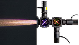
3台の高出力LEDを使用した光源のビームプロファイル
Click to Enlarge
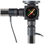
2台のLED光源。構成例1と同じですが、青のLEDを取り外しています。
高出力光源に組み込まれているLED単体のZemax用光線データをご用意しております。 下の型番横の「資料」の赤いアイコン(![]() )をクリックすると、ZIP形式のフォルダをダウンロードすることができます。ZIPフォルダには、資料ファイルとZemaxで使用するための光線データファイルが含まれています。
)をクリックすると、ZIP形式のフォルダをダウンロードすることができます。ZIPフォルダには、資料ファイルとZemaxで使用するための光線データファイルが含まれています。
- 資料ファイル: このドキュメントには、ZIPフォルダ内のデータファイルの種類とご利用にあたっての基本情報が入っています。 また、それぞれのドキュメントの種類と対応するファイル名のリストも含まれています。
- 光線ファイル: Zemaxで使用するための光線データが含まれているバイナリファイルです。
右の表で「a」の上付き文字が付いているLEDについては、次のような情報もZIPフォルダ内に入っています。
- スペクトルデータ: このSPCファイルもZemaxでの使用を想定したデータです。
- CADファイル: LED単体の形状を示すファイルです。 筐体を含むマウント付き高出力LEDの寸法については、当社がご提供している補足図面をご覧ください。
- Zemaxファイルのサンプル: サンプルファイルには、Zemaxで使用する際の、光線ファイルとLED単体のCADモデルに関する推奨される設定と配置が含まれています。
右の表は各LEDに対応する光線ファイルおよび参考資料の一覧です。
| Compatible Cerna® Components |
|---|
| Epi-Illumination |
| WFA2001 Epi-Illuminator Module |
| Trans-Illumination |
| Illumination Kits |
Cerna®顕微鏡システムでマウント付きLEDの使用
当社のCerna顕微鏡プラットフォーム内において、狭帯域スペクトル版もしくは広帯域スペクトル版のマウント付きLEDが下記の様々な用途において使用できます。
- 蛍光顕微鏡
- 明視野顕微鏡
- 近赤外・赤外(NIR/IR)顕微鏡
Cerna顕微鏡システムでマウント付きLEDをご使用になる場合、350~700 nm用に最適化されたARコーティング付き光学系が組み込まれたシングルキューブ落射照明モジュール(型番WFA2001)を用いて取り付ける方法があります。 マウント付きLEDと落射照明モジュールは、外ネジ付きのカプラ(型番SM1T10、WFA2001に付属)で接続します。カプラは刻み目付きロッキングリング(型番SM1NT、同じくWFA2001に付属)で手で締め付けます。 マウント付きLEDはドライバ(別売り)で駆動します。 マウント付きLEDに適したドライバの選定は「LEDドライバ」のタブをご覧ください。複数のマウント付きLEDを落射照明モジュールに接続したい場合には当社までご連絡ください。
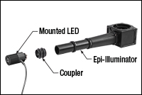 Click to Enlarge
マウント付きLEDと落射照明モジュールWFA2001の接続。
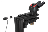 Click to Enlarge
マウント付きLEDは落射照明モジュールを顕微鏡に取り付ける前でも後でも接続できます。
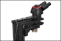 Click to Enlarge
マウント付きLEDと落射照明モジュールを取り付けたCerna顕微鏡
イメージングに適したマウント付きLEDの色スペクトルの選択には「概要」タブをご覧ください。なお、落射照明モジュールは波長が350~700 nmの照明光源用に最適化されています。
いくつかのマウント付きLEDは当社の透過照明用照明キットに対応します。 コリメート光学素子が特定のビーム特性用に最適化されているため、キットに含まれていないLEDの使用をご希望の場合には当社までお問合せください。
駆動するLEDから最大の光パワーを出力させるには、LEDの最大電圧および最大電流と同等あるいはそれ以上の電圧と電流を出力できるドライバが必要です。この条件を満たすドライバが下表の「Recommended Drivers」に記載されています。
| Compatible Drivers | LEDD1B | UPLEDa | DC40a | DC2200a | DC4100a,b | DC4104a,b |
|---|---|---|---|---|---|---|
| Click Photos to Enlarge | 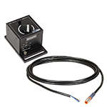 | 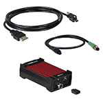 | 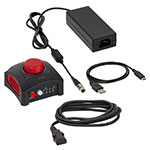 | 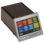 | 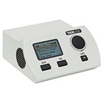 | 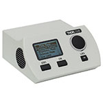 |
| LED Driver Current Output (Max)c | 1.2 A | 1.2 A | 4.0 Ad | LED1 Terminal: 10.0 A LED2 Terminal: 2.0 Ae | 1.0 A per Channel | 1.0 A per Channel |
| LED Driver Forward Voltage (Max)f | 12 V | 8 V | 14.0 Vd | 50 V | 5 V | 5 V |
| Modulation Frequency Using External Input (Max) | 5 kHzg | - | 5 kHzg | 250 kHzg,h | 100 kHzg (Simultaneous Across all Channels) | 100 kHzg (Independently Controlled Channels) |
| External Control Interface(s) | Analog (BNC) | USB 2.0 | USB 2.0, TTL, and Analog (BNC) | USB 2.0 and Analog (BNC) | USB 2.0 and Analog (BNC) | USB 2.0 and Analog (8-Pin) |
| Main Driver Features | Very Compact Footprint 60 mm x 73 mm x 104 mm (W x H x D) | USB-Controlled | Driver Current Up to 4.0 A, Manual and USB-Controlled | Touchscreen Interface with Internal and External Options for Pulsed and Modulated LED Operation | 4 Channelsb | 4 Channelsb |
| EEPROM Compatible: Reads Out LED Data for LED Settings | - | |||||
| LCD Display | - | - | - |
| Posted Comments: | |
Víctor Rico
(posted 2024-11-08 13:07:35.613) Dear Thorlabs team,
I’d like to bring something to your attention. I noticed a slight discrepancy between the spectral data provided for the LED530L4 LED diode (file: M530L4_data.xlsx) and the corresponding graph displayed on the website. While the spectrum shape is consistent with the reported data, the data in the file appears in a stepwise, “staircase” format, whereas the online graph shows a smoother, continuous curve. Liping Sun
(posted 2024-08-25 08:37:51.487) We regulate the outgoing light power of M310L1 and M340L5 by adjusting the DC current of LEDDIB controller in the experiment. However, when the maximum forward current of LEDDIB to M310L1 and M340L5 is adjusted, The measured optical power can not reach the minimum output power of M310L1 and M340L5. What might be the cause? jjadvani
(posted 2024-09-02 05:40:01.0) Dear Ling, Thank you for providing feedback. Reduced power output can occur for a variety of causes. I will contact you directly to troubleshoot this. Shaodi ZHU
(posted 2024-08-22 15:02:48.837) We would like to design our illumiation system using M265L5 and M280L6. Could you please provide the data file for simulation of these led light source? (e.g. .dat for zemax)
Instead, if possible, could you provide the LED chip model that has been mounted upon? jjadvani
(posted 2024-08-22 06:04:59.0) Dear Shaodi, thank you for contacting Thorlabs. I will contact you personally to provide you information you need. gong liu
(posted 2024-04-10 03:18:50.49) Could you please share the light-emitting area of the LED in M730L5? jjadvani
(posted 2024-04-10 07:49:08.0) Dear gong, Thank you for your inquiry. Emmiter size of this LED is 1 mm x 1 mm. You can check this in spec sheet of LED. Haojie Zhang
(posted 2024-04-02 22:06:25.553) How can i use the EEPROM pin of MBWHL4 without your specific LED drivers? dpossin
(posted 2024-04-02 11:39:28.0) Dear Haojie,
Thank you for your feedback. I reach out to you in order to provide further information. Yuhao Yuan
(posted 2024-01-18 16:35:05.54) Hi there, I would like to maximize the output power of M1300L4 after collimation with SM2F and ACL50832U. But the output average power is about 30 mW which is far less than 180 mW. Do you have any suggestions to increase the power? dpossin
(posted 2024-01-19 07:25:48.0) Dear Yuhao,
Thank you for your feedback. I reach out to you directly to discuss your application. AMUL RAMSOGE
(posted 2023-09-23 17:16:47.67) Can you please share any documents elaborating how to hold M280L6 mechanically and standard accessories available with Thor labs for holding. hchow
(posted 2023-09-26 05:59:21.0) Dear Mr. Ramsoge, thank you for your enquiry. I will personally reach out to you to provide more information. Thank you. Warren Massey
(posted 2023-09-06 13:17:47.347) The datasheet says to power this LED with no more than 1000mA, yet all the optical ratings for the LED are when it is powered with 1000mA suggesting a lower/safer current not be used during operation (i.e., no current safety margin). That leads me to believe that 1000mA is actually a NOMINAL maximum current and that there is some tolerable variation allowed around that value. What is the acceptable range of maximum operating current? FWIW, looking at your suggested companion "upLED driver", it says: "LED Current Accuracy: ±(1% + 10 mA)" which would suggest that 1110mA is an acceptable upper current limit given that this suggested driver might supply just that. Looking at your suggested companion "basic LED driver", its current limit is a manually-adjusted potentiometer, whose setting depends upon on some adjacent ballpark silkscreen labels so I doubt it's much better at establishing a ±10% current limit. hchow
(posted 2023-09-11 05:33:30.0) Dear Mr. Massey, thank you for your feedback. We suggest our customer to not exceed the maximum driving current of the LED, as adverse effects to the LED can occur. If too much current is used, the LED will start to overheat, causing a colour shift, or burn out, and at the worst case, fragmentation of the LED. The upLED LED driver is able to read the EEPROM chip on board the mounted LED and is able to automatically adjust the current. Moreover, there is a current limit switch on the manual LED driver, LEDD1B, which limits the maximum driving current. In either cases, the maximum current is not exceeded. Pedro Mecê
(posted 2023-07-25 14:05:38.44) Hello, I am interested on the M810L3 because its high irradiance and near-infrared wavelength. If I understand well this product is obsolete. What are the similar alternatives that you can propose?
Thanks hchow
(posted 2023-07-26 03:23:39.0) Dear Mr. Mece,
thank you for your feedback. Actually, the M810L3 is still available for purchase from us. I just checked, we still have stock of this item. In any case, I will contact you to provide more information. Thank you. Jackson Knappen
(posted 2023-04-26 07:46:00.55) We measured two separate MNWHL4 4900K LEDs using a calibrated JETI spectroradiometer. Our measurements showed a spectrum that was significantly different from the Thorlabs spec with significantly more blue energy and a CCT closer to 6500K or even greater. hchow
(posted 2023-04-27 04:06:02.0) Dear Mr. Knappen, thank you for your feedback. I will personally reach out to you to find solutions to the problem you are facing. Thank you. Jay Han
(posted 2023-02-13 12:53:31.247) Hello, I am using LED 940nm with DC2200 driver and I have the following questions in TTL modulation mode.
1.I would like to know the time/delay response vs. the LED current setting.
2.I want to know the rising/falling time of output according to the LED current.
Thanks,
Jay hkarpenko
(posted 2023-02-15 10:32:32.0) Dear customer,
thank you for your feedback. We have a documentation about that. I will send you our test protocol regarding the rise and fall time measurements of the DC2200 LED driver. Kevin M
(posted 2023-01-31 15:12:23.323) Hello,
The LED works as specified. Is it vacuum compatible?
We would be operating at around 10^(-5)mb
Thanks,
Kevin hchow
(posted 2023-02-01 06:06:55.0) Dear Kevin, thank you for your feedback. Unfortunately, the M1050L2 isn't rated to be used in a vacuum environment. Thermal paste and solder is used in the internal LED's PCB and additionally the housing is anodized, all of which can begin to outgas in a vacuum. shlomi tapiro
(posted 2022-12-27 16:52:42.983) HI
I need for my work the item M810L3 because I need to use a wavelength of 810nm, plus the whole assembly of this particular item fits me in the array.
I see with you that it is obsolete, what is the item that replaces this item?
I can't find anything exactly like it, and I have to buy this product
In addition
I have other arrays that I have already purchased and I am required to maintain them.
What to do? dpossin
(posted 2022-12-28 06:34:33.0) Dear Shlomi,
Thank you for your feedback. Unfortunately currently we do not offer mounted LEDs emitting at 810nm. I reach out to you in order to discuss alternatives. Kath Wood
(posted 2022-11-16 16:53:58.4) Hi - does the spectrum plot in the Spec Sheet have the correct x-axis labels? It looks off. The peak looks more like 480 nm - that's fine, I just wanted to check...
Thanks for your help!
Katherine hchow
(posted 2022-11-21 03:11:52.0) Dear Katherine,
thank you for your valuable feedback. I will personally reach out to you to provide more information about the M490L4 in question.
Thank you. Chuanpu Liu
(posted 2022-09-28 16:29:45.673) For the M405L4 - 405 nm, is there a power supply available in Thorlabs? Thanks! dpossin
(posted 2022-09-30 03:14:50.0) Dear Chuanpu,
Thank you for your feedback. We offer several options in order to drive our mounted LEDs like the M405L4. You could either use our most basic LED controller namely the LEDD1B or use a more advanced controller. Please see our selection here: https://www.thorlabs.de/navigation.cfm?guide_ID=2109. I reach out to you in order to provide further assistance. Jonas Kublitski
(posted 2021-12-08 15:18:07.843) Hi,
the LED works as expected. However, this is a mounted LED, which means people will keep threading it in and out all the time. It is super annoying to do so with the cable.
My suggestion:
It would be perfect if one could disconnect the cable from the LED, such that while mounting one wouldn't have to mind the cable.
Moreover, having the cable like this, makes you break it quite easily, as you keep twisting it..
I believe this applies to all mounted LED..
Thanks
Jonas wskopalik
(posted 2021-12-13 03:22:35.0) Dear Jonas,
Thank you very much for your feedback and your suggestion!
I will forward your idea to our engineering team so they can consider it for future design improvements. I will also reach out to you directly. Wijnand Twivey
(posted 2021-11-21 13:31:31.543) Dear SIr,
Wat ik can not find is the type of cable, wire size and the lenght of the attached cable.
Can you send me this informatie,
With kind regards,
Wijnand twivey
Electrical Hardware Engineer / Eplan Engineer.
Kremer industriele Automatiserings bv. soswald
(posted 2021-11-25 03:10:53.0) Dear Wijnand,
thank you for your feedback. I have reached out to you directly to provide the required information and discuss your application in more detail. Nicolas Villa
(posted 2021-11-20 07:32:34.987) Hello,
I have a mounted LED M505L3. Is the DIY SM1-Threaded collimation assembly compatible with the M505L3 ?
Best regards,
Nicolas dpossin
(posted 2021-11-24 10:14:13.0) Dear Nicolas,
Thank you for your inquiry. The M503L3 can be mounted to any DIY SM1 threaded collimation adapter. However the easiest optoin is to use our collimation adapter SM1U25-A: https://www.thorlabs.de/thorproduct.cfm?partnumber=SM1U25-A Chen Chuan Teo
(posted 2021-08-26 15:56:18.29) Hi Mates,
I have bought this LED and i wish to download the certificate of RoHS, but seem like cannot download from website. Can you please email me the certificate of this item? MKiess
(posted 2021-08-30 11:09:23.0) Dear Chen Chuan Teo, Thank you for your inquiry. Sorry that the download is not working at the moment, we will fix this issue as soon as possible. I have contacted you directly to send you the certificate. Tianxiang Ling
(posted 2021-07-14 17:25:51.17) Maximum Irradiance was 13.5 µW/mm2
Measured at a Distance of 200 nm?
I want to know the distance is 200 nm or 200 mm?? soswald
(posted 2021-07-15 08:54:20.0) Dear Tianxiang Ling,
thank you for your feedback. The sensor that was used to measure the typical irradiance of the MBB2LP1 was placed at a distance of 200 mm from the LED. Torsten Rehwald
(posted 2021-07-06 03:45:40.533) Dear Sir or Madam,
could you please provide me information about the correct protective glasses during the use of the LED M450LP1.
Thanks a lot for your support.
Kind regards
Torsten Rehwald MKiess
(posted 2021-07-07 11:25:54.0) Dear Torsten, thank you very much for your inquiry. I contacted you directly to discuss the specific requirements. Jiun-Yann Yu
(posted 2021-05-14 19:09:13.06) Hi,
I was wondering what the maximum output (optical) power is for this LED. Does it go beyond 1 Watt? The spec on your website doesn't seem to provide any reference or estimation for this.
Thanks. MKiess
(posted 2021-05-18 07:24:58.0) Dear Jiun-Yann, thank you very much for your inquiry. The specified optical power of, typically 542mW, for the M810L4, you will get when driving the LED with the maximum current of 1000mA. Therefore, you will not achieve 1W power with this LED. I have contacted you directly to discuss further possibilities. Lili Tang
(posted 2020-11-09 14:16:30.477) I require the wavelength range of the LED source,but products were discontinuded,so i cannot find it ,please send it to me ,thanks. dpossin
(posted 2020-11-10 05:37:50.0) Dear Lili,
Thank you for your feedback. Even though the products has been discontinued, the spec sheets can be still found under "drawing and documents" here: https://www.thorlabs.com/thorproduct.cfm?partnumber=MCWHL5&pn=MCWHL5. I am sending you the specsheet anyway. Julian Kleber
(posted 2020-09-21 03:05:01.9) Hi,
I tried to download the datasheet of the M940L3 for several days now. It seems as if this link isn't working anymore. Could you fix this so that I can download it?
https://www.thorlabs.com/_sd.cfm?fileName=25177-S01.pdf&partNumber=M940L3
Is there any information on the EEPROM that is unique for a specific mounted LED ? (E.g. serial, timestamp,....)
Can I read this information without using your LED drivers?
Best
Julian MKiess
(posted 2020-09-22 04:14:25.0) Dear Julian, thank you very much for contacting Thorlabs. I have sent you the specification sheet directly.
The EEPROM chip stores information regarding current, voltage, wavelength etc. This information can be accessed via our Thorlabs controllers. This includes information such as type and serial number of the LED itself. Niall Martin
(posted 2020-07-01 07:52:59.99) I think the pin number on the data sheet for this product are incorrect according to the standard for M8 connectors
It seems pin 3 and pin 4 are labelled the wrong way round, but pins 1 and 2, and the wire colours are correct
Please could you check and confirm.
I am basing this on the fact that all other manufacturers I can find for m8 cables asundararaj
(posted 2020-07-07 10:11:40.0) Thank you for contacting Thorlabs. The labeling on the pin diagram of the CON8ML-4 is correct as per the drawing on the website. malcolm northcott
(posted 2020-04-22 19:54:42.987) Is it possible to get an excel spreadsheet with he measured special output for this LED MKiess
(posted 2020-04-24 05:31:55.0) This is an response from Michael of Thorlabs. Thank you very much for your inquiry. An Excel file with the spectral data can be downloaded from our website, by calling up the information of the desired LEDs in the info column. STATICE MP
(posted 2020-04-03 13:08:57.1) Good morning,
Do you have an other reference to propose ?
Waiting for your feedback aqap
Than you very much
M PIELLARD MKiess
(posted 2020-04-06 04:12:02.0) This is a response from Michael at Thorlabs. Thank you very much for your inquiry. An alternative to the M505L3, Mounted LED, is the newer version of this LED. This LED has the item number M505L4. Simon Meaney
(posted 2020-03-05 18:19:25.8) The technical drawings on the MCWHLP1 and MWWHLP1 Spec Sheets are incorrect.
They list the diameter as " 57.0mm (1.20") "
57mm is 2.24" which matches the AutoCad PDF for the products. MKiess
(posted 2020-03-06 06:54:05.0) This is a response from Michael at Thorlabs. Thank you very much for your inquiry. Thank you very much for this information. That is correct. We will correct it immediately. Pawel Hermanowicz
(posted 2020-01-12 07:10:11.1) Hi,
I would like to ask whether the ray sets for the M455L4 and M660L4 mounted LEDs are available, in ASCII (preferably) or Zemax format? wskopalik
(posted 2020-01-13 10:20:33.0) This is a response from Wolfgang at Thorlabs. Thank you very much for your inquiry!
I will contact you directly regarding these files. Bernd Polder
(posted 2019-11-29 08:01:58.357) In the website you also show a M595L4 with very good output power. I am interested in this product, but I only find the M595L3 in the ordering section. How is it possible to order thise M595L4 version?
Thank you
Best regards
Bernd Polder lmorgus
(posted 2019-12-02 11:14:24.0) A response from Laurie at Thorlabs to Bernd: I will reach out to you via email concerning your inquiry to purchase our next generation 595 nm LED, for which we had accidentally posted some information ahead of the formal release. Dongbin Lim
(posted 2019-09-30 17:00:34.623) Hello,
We would like to inquire about your product M470L3 certification.
We are using your product and we need your product certificate to be certified for the product we are developing.
I am writing to ask you this question because I cannot see Rohs certificate on your homepage.
I would appreciate it if you could send me my email with the certificate for M470L3.
Thank you. MKiess
(posted 2019-10-07 09:01:11.0) This is a response from Michael at Thorlabs. Thank you very much for your inquiry! In general you can find the RoHs certificates on our website for the respective articles. If you click on the red icon in the column 'Documents' on the product page where the article number is listed, you can download the certificates.
Since the M470L3 has been replaced by the newer M470L4, you can find the certificate under the following link:https: //www.thorlabs.com/thorproduct.cfm?partnumber=M470L3&pn=M470L3#4478 Evyatar kassוs
(posted 2019-08-07 12:13:37.653) I am using the M265L3 with dc2200 driver but can not get short pulses, what are the rise and fall times of M265L3 ? dpossin
(posted 2019-08-09 07:40:09.0) Hello Rafael,
Thank you for your request. It should be possible to create pulses of µs length with your setup. I am reaching out to you in order to give you further support. gjorgensen
(posted 2019-03-11 13:37:52.857) Hello-
I need to time a camera trigger after turning on your LED, but I could not find and spec for LED rise time in yoru documentation on the web site. Could you please let me know how long a delay I need to place in my code between the time I turn on the LED and triggering to camera so I am insured the LED has obtained at least 90% brightness? Thank you for your assistance. nreusch
(posted 2019-03-19 08:03:40.0) This is a response from Nicola at Thorlabs. Thank you very much for your inquiry! We do not specify rise and fall times of LEDs, but typical values are in the ns range. The rise and fall times of LED systems are, however, limited by the driver electronics in most cases. Using one of our LED drivers leads to response times in the several µs range. bhebert
(posted 2018-12-20 10:17:05.867) Do you offer a variety of this the uses the ushio EDC940DS-1100-S5 or can a special version be made? wskopalik
(posted 2018-12-28 05:36:06.0) This is a response from Wolfgang at Thorlabs. Thank you very much for your inquiry!
Unfortunately, we don't offer a mounted LED which uses this particular LED chip. I have however looked at the data sheet of this LED chip and the M940L3 seems to be quite similar in performance.
I will contact you directly to discuss your requirements in detail. yu-pu.lin
(posted 2018-12-19 10:29:50.383) What is the approximative spot size of the collimated beam at 20-50 mm distance using the SM2F32 Adjustable Collimation Adapter? (LED = M940L3)
Thank you! YLohia
(posted 2019-01-04 04:00:51.0) This is a response from Michael at Thorlabs. Thank you very much for your inquiry! I will perform a Zemax simulation with the M940L3 in combination with the adjustable collimator to determine the divergence angle and thus the resulting beam diameter at a distance of 20-50mm. I will send you the results directly. fcouweleers
(posted 2018-12-17 10:55:02.65) can you share which LED (probably OSRAM) is present in this assembly nreusch
(posted 2018-12-21 02:34:32.0) This is a response from Nicola at Thorlabs. Thank you for your inquiry! Unfortunately, we do not share the LED chip details of our mounted LEDs in general. Please contact your local Tech Support Team if you need specific information about the characteristics of the chip. joe.bron
(posted 2018-11-21 10:48:45.81) Will a diffuse condenser lens have much effect on its collimation compared to a clear one? wskopalik
(posted 2018-11-29 07:17:48.0) This is a response from Wolfgang at Thorlabs. Thank you very much for your inquiry!
The quality of the collimation, i.e. the remaining divergence, will be roughly the same with or without a diffuser. The diffuser smoothens the intensity distribution of the beam and makes it more homogeneous. It will also smoothen the edge of the beam a bit so the beam would look a bit wider. The main disadvantage of a diffuser is that the transmitted power would be lower than without a diffuser due to absorption and reflection. user
(posted 2018-10-31 11:23:54.427) Hi,
Can I know if M415LP1 compatible with the LED driver LEDD1B?
Thanks nreusch
(posted 2018-11-09 10:09:57.0) This is a response from Nicola at Thorlabs. Thank you for your inquiry! The forward voltage of LEDD1B is high enough to drive M415LP1, but the maximum current is 1.2 A only, whereas the maximum drive current of the LED is 2 A. To reach the specified minimum output power of 1640 mW, you would need to apply a higher current than LEDD1B can provide. I therefore recommend using DC2200 as driver. mabashin
(posted 2018-10-29 14:22:57.28) Hello could you please send/share Zemax files for M625L3 and M730L4 LED sources? nreusch
(posted 2018-11-09 10:11:22.0) This is a response from Nicola at Thorlabs. Thank you for your inquiry! Unfortunately, we do not have Zemax files for these two LEDs. I will, however, send you ray files and an instruction on how to load them into Zemax. p.adhikari
(posted 2018-09-18 13:47:18.12) Need a high output green LED > 10,000 mcd nreusch
(posted 2018-09-24 11:08:18.0) This is a response from Nicola at Thorlabs. Thank you for your inquiry. Unfortunately, we specify our LEDs by means of radiometric measures only. I will contact you directly to provide assistance for the conversion into photometric units. daming.chen
(posted 2018-07-31 12:39:05.987) Hello,
For the M850LP1 LED, which power supply product should be purchased?
Thank you. mmcclure
(posted 2018-07-31 08:07:54.0) Hello, thank you for contacting Thorlabs.
For M850LP1 we recommend to use DC2200 because only this device can drive the LED at its maximum current of 1.5 Ampere.
Other drivers (LEDD1B, DC4100, DC4104) would basically work with M850PL1 but with reduced optical output power. zh_tooleng
(posted 2018-07-31 17:30:08.13) hello,I am going to buy a light source to use in my microscopic system.Here are my list:
[M1300L3],[LEDD1B],[ACL2520U],[SM1RR],[SM1V05][SM1L03]
Do they meet my needs?
And I want to know the best distance between the LED and the lens.
Thank you! swick
(posted 2018-08-06 04:14:53.0) This is a response from Sebastian at Thorlabs. Thank you for the inquiry.
The selection look adequate for collimating the M1300L3.
Basically the distance of the lens to the LED should be the back focal length.
The best distance between LED and lens depends on the optical path in your microscope.
I recommend to start with the back focal length and optimize the distance until you get best results. I contacted you directly for assistance. karol.686
(posted 2018-07-12 08:16:48.163) Hi, we are going to buy M625L3 from Thorlabs, we would like to know the spatial and temporal coherence length of this diode. Thanks swick
(posted 2018-07-18 03:39:02.0) This is a response from Sebastian at Thorlabs. Thank you for the inquiry.
The spatial coherence for LEDs is typically very small.
We do not test the spatial- or temporal coherence for our LEDs so we can not provide specific data. I contacted you directly for further assistance. alicia.gomis-berenguer
(posted 2017-09-28 12:19:44.79) I would like to know what is the mode of operation of the MCWHLP1 LED using as a power supply LIU-PS LIU Series Power Supply. Is it a continuous wave (on all the time)? or is it a pulse modulation (on/off with time)? Thanks! swick
(posted 2017-10-03 03:55:45.0) This is a response from Sebastian at Thorlabs. Thank you for the inquiry.
The LIU-PS is a voltage source and designed for our LIU-Series, which is a LED array light source (20 individual LEDs). LIU-PS will not work with our high-power LEDs. We recommend to use current sources like switching drivers (e.g. LEDD1B). I will contact you directly for further assistance. carlos.macias
(posted 2017-06-28 17:57:47.053) Hello. Is it possible to couple MNWHL4 to a multimode fiber or light guide? wskopalik
(posted 2017-07-04 04:26:30.0) This is a response from Wolfgang at Thorlabs. Thank you very much for your inquiry!
Yes, it is possible to couple this LED to a multimode fiber or a light guide. We don't have a ready-to-use product for this, but you can use Thorlabs' components for the coupling.
I have contacted you directly to discuss your application and the necessary components in more detail. jpaufiqu
(posted 2017-06-20 13:31:54.28) Hi,
I see high frequency fluctuations on the flux output generated by the LED at 660nm.
I use the M660 and the LEDD1B controller in continuous mode, below the maximum current (using the setting 1000 mA, to a rather high setting in this mode ~50 to 70% of the knob range).
Fluctuations appear at the level of the kHz: we sample our signals at about 1.05 kHz, and observe sporadic drops (down to ~30% of the nominal value). Are you aware of a feature of the controller or the LED driver or of the LED electronics which would be related to this effect? wskopalik
(posted 2017-06-22 06:01:47.0) This is a response from Wolfgang at Thorlabs. Thank you very much for your inquiry!
The only expected fluctuation on the LEDD1B would be the ripple on its current which is specified to 8mA max. You use the LEDD1B at about 500-700mA so the ripple would be less than 1% of the current and couldn't account for the large drops in power you see.
I will contact you directly to discuss this issue in further detail so we can find the reason for these power drops. ken_Chin
(posted 2017-02-09 17:26:16.85) does M365LP1 have a calibration report with NIST or PTB Traceability? wskopalik
(posted 2017-02-10 02:58:01.0) This is a response from Wolfgang at Thorlabs. Thank you very much for your inquiry.
These LEDs are tested during production to ensure that they work properly and that they emit the specified power. But unfortunately they cannot be calibrated.
I have contacted you directly to discuss your requirements. eddie.ross
(posted 2016-09-27 10:40:13.433) Can you provide the switch off time for the MBB1L3 LED and could you also provide a clarification as to whether this LED uses phosphor to provide white light? swick
(posted 2016-09-28 04:39:43.0) This is a response from Sebastian at Thorlabs. Thank you for the inquiry.
The MBB1L3 LED may not turn off completely when modulated at frequencies above 1 kHz with a duty cycle of 50%.
For modulation at frequencies above 1 kHz, the duty cycle may be reduced. For example, 10 kHz modulation is attainable with a duty cycle of 5%.
The broadband emission is luminescence generated by Phosphor. alee
(posted 2016-06-22 14:18:07.74) I want to use an LED as an excitation source on an olympus BX60 microscope. you sell the product for this, however it uses a 2" lens and when I look down the microscope illumination port it has a 25-30mm diameter restriction in it meaning most of the light from the LED would be blocked. So would it be better to use a 1" lens to collimate the LED as described below, rather than the product specified for the olympus microscope, and how would I fix this to the microscope, do you sell the olympus adapter without a lens? besembeson
(posted 2016-06-22 01:59:06.0) Response from Bweh at Thorlabs USA: Due to the large divergence angles of these LEDs, the 2" diameter lenses will collect more power than the 1" optic. For example, with a 60deg half angle divergence LED and a 20mm (or 12mm BFL) 1" lens, you will only be capturing about 56% of the LED output, which may or may not be suitable depending on your application. Should you need to use the 1" LED collimators, you would need an SM2T2 and we can provide the corresponding 2" adapter without the lens inside. ludoangot
(posted 2016-05-30 08:16:41.943) Very pleased with your offering a 2" adjuster. Unfortunately, 3 out of 4 of the adjusters I am working with (ACP2520, SM2P50 and SM1P25) are hard to rotate. From my first observations, it seems it may be related to the environment conditions (temperature, humidity). Would it be possible you provide your customers with the proper working environment conditions for the SM2P50 and SM1P25? Note that one SM1P25 doesn't have the problem at all, but the ACP2520 did (I modified it myself for smooth rotation), as well as the latest SM1P25 and SM2P50 I've received. I have contacted you and provided a detail report of my observations but only received a proposition from Thorlabs application engineer Yi-Ma to change the parts in question. This offer doesn't seem to address my question nor would it help if the replacements have the same issue. besembeson
(posted 2016-05-31 03:25:32.0) Response from Bweh at Thorlabs USA: Thanks for your feedback. We will check to see if we can replicate your observations regarding SM2P50 and SM1P25 performance under various humidity conditions. I will be in touch via email. cbrideau
(posted 2016-02-12 19:46:34.71) Would it be possible to purchase the extra-thick SM1-threaded and SM2-threaded retaining rings for Aspheric condenser lenses separately? I use the 1" and 2" diameter aspheric condensers fairly often, and the regular retaining rings don't work well with them. shallwig
(posted 2016-02-18 02:30:50.0) This is a response from Stefan at Thorlabs. Thank you very much for your feedback. We have contacted you directly to offer you these retaining rings separately. juandspcf
(posted 2015-10-24 13:05:56.75) Dear
I would like to use your module M625L3 with your Adjustable Collimation Adapter ACP2520-A, but I also would like to know how much power is lost after of the collimation step because I want to focus the collimated beam and make a filtering using a pinhole
Juan shallwig
(posted 2015-10-27 05:04:34.0) This is a response from Stefan at Thorlabs. Thank you very much for your inquiry. I just tested this, the output power of the M625L3 without collimator attached measured with an integrating sphere was 840mW. The output power of the well collimated LED using the ACP2520-A was 430mW. The min/max power level measured with this collimator at its limit stops was 360mW and 640mW. I will contact you directly to discuss your application in detail. sjs09
(posted 2014-08-20 12:09:39.15) Dear Thorlabs,
The thorlabs LED collimation page describes using an SM1 lens tube and aspheric lens. It seems you advise we buy an adjustable 1/2" lens tube and extend it with a 0.30" adapter.
Since ThorLabs sells an adjustable 1" lens tube (SM1V10) this seems rather redundant, unless the thread inside the LED casing does not allow it to collimate. There is no information about the depth of the SM1 thread inside the LED casing.
My question is this: Could you tell me whether SM1V10 would be able to collimate the LED on its own, or does it require SM1V05 and the 0.30" spacer? If this is the case, I suggest you extend the thread on the LED case, if possible, to simplify the process.
Kind regards,
Sam S myanakas
(posted 2014-08-20 11:11:48.0) Response from Mike at Thorlabs: Thank you for your feedback. The thread depth is stated within our mechanical drawings (http://www.thorlabs.com/thorcat/MTN/M530L3-AutoCADPDF.pdf) which can be found by clicking on the red "docs" icons by the items numbers below. The thread depth for these LEDs is 6 mm. Based on this feedback we have added this information to the Overview tab of the web page. The SM1V10 can be used in place of the SM1V05 and SM1L03 pairing. However, the current recommendation allows for a slightly longer translation range of the optic due to the 7.6 mm depth of the internal threading in the SM1L03. The Collimation tab has also been updated to include the use of the SM1V10 as a collimation solution for these LEDs. Carlo.Vicario
(posted 2014-05-14 11:11:40.42) Dear Sirs,
I would like to have information about the dependence between the emitted power versus the LED driving current.
Is this relationship linear?
Best regards,
Carlo shallwig
(posted 2014-05-15 08:38:18.0) This is a response from Stefan at Thorlabs. Thank you very much for your inquiry. On page 3 of the manufacturer’s spec sheet you can find a curve showing current vs. output power on a relative scale to 350mA . In this range you will see a linear relationship, however we have no information how this relationship changes in the range from 350mA to 700mA. We have tested this LED only at 700mA as this is the maximum drive current our heat sink system can also manage. You can find the manufacturer spec sheet of this LED on our website here: http://www.thorlabs.com/thorcat/23300/M1050L2-MFGSpec.pdf
Our spec sheet can be found here: http://www.thorlabs.com/thorcat/23300/M1050L2-SpecSheet.pdf
In general information about this relationship if available, can be found in the manufactures spec sheet. I hope this information helps you further, please let me know if there is anything else you need. a.andreski
(posted 2014-03-09 20:08:42.05) Can we order one of these packages but with the LED and the mounting heatsink not assembled/soldered at Thorlabs? We have our own assembly and thermal film bonding process.
Aleksandar tschalk
(posted 2014-03-31 09:25:56.0) This is a response from Thomas at Thorlabs. Thank you very much for your inquiry. We will contact you directly with a quotation. jan.moritz.ellinghaus
(posted 2013-11-22 08:26:13.437) Dear Sir or Madame,
Can you send me the ray file for Zemax for the LED MWWHL3 Warm White 3000K? I could not quite identify which LED is actuall mounted.
I would like to simulate the combination of this LED with the COP1-A in Zemax and combine this with some additional optical elements.
Thank you in advance for your help!
Kind regards,
Jan Ellinghaus tschalk
(posted 2013-12-02 03:35:07.0) This is a response from Thomas at Thorlabs. Thank you very much for your inquiry. We do have Zemax files available and i will contact you directly with more detailed information. jan.haschke
(posted 2013-08-23 12:24:08.587) Dear Sir or Madam,
I have a question concerning the mounted LED system you supply. We are using it as a BIAS illumination source in a measurement setup.
I was wondering what the EEPROM on the PCB is for. Is it in any way affecting the current supply of the LED? In particular, is it possible that it creates some noise on the current supplying the LED?
Thank you in advance for your help!
Best regards,
Jan Haschke tschalk
(posted 2013-08-26 10:08:00.0) This is a response from Thomas at Thorlabs. Thank you very much for your inquiry. Our Mounted High Power LEDs are all equipped with an EEPROM where the operating parameters are stored. The LED drivers DC2100, DC4100 and DC4104 read out the EEPORM and set the maximum operating current to the stored value. This way a current overload can be avoided. The driver LEDD1B is not able to read out the EEPROM and the current limit has to be set manually. The EEPROM will not cause noise to the current supply. I will contact you directly with more detailed information. jvigroux
(posted 2012-09-24 10:22:00.0) A response form julien at Thorlabs: Than you for pointing this out. We corrected the presentation on our website so that now the wrench recommended is the SPW801. We will send you a replacement for the lens together with the new case. gir
(posted 2012-09-20 16:20:24.0) One other thing: On the application page where it explains how to collimate the LED, it says to use a SPW602 spanner wrench to secure the aspheric lens with one retaining ring on each side. I did this, and the SPW602 carved a circle on the front surface of the lens. Please change this text to instruct people to use a different spanner, so they don't inadvertently scratch their collimating lens. gir
(posted 2012-09-19 20:09:14.0) Hi: I have a minor issue to relay about the packaging of the mounted LEDs. I bought an M735L3 late last week and received it today. The plastic case it comes in is not well designed or built. Specifically, the red latch on front broke off while I was trying to figure out how to open the case. And it took two of the black plastic hinge-posts with it, so even when I put the latch back on the case, the case won't stay shut anymore. It seems silly to provide these in a hard shell case if the latch can't withstand a bit of force from a novice case-opener. jlow
(posted 2012-08-30 14:23:00.0) Response from Jeremy at Thorlabs: Is your power supply a voltage source or is it a current source? It is highly recommended that you drive these LEDs with a current source instead. If you used a 5V constant voltage source (@ 3A), then you will most likely be injecting 3A of current into this LED and thus destroyed it (max. current for MCWHL2 is 1.6A). Please note that the typical forward voltage for the MCWHL2 is only about 3.5V. It could also be that you have not connected this correctly. I will get in contact with you directly to check on the details on your setup. doron.azoury
(posted 2012-08-30 11:16:39.0) Hi,
I just recieved the MCWHL2 LED. I control it by a DC power supply. I set the voltage limit to ~5V and tried to rise the current, but the LED doesn't seem to be working. Am I doing something wrong? (the DC supplier can deliver up to 3A) jlow
(posted 2012-08-22 08:19:00.0) Response from Jeremy at Thorlabs: We do not have a precise number for this, but based on some old data, the rise and fall times are both on the order of 20ns or so. riclambo
(posted 2012-08-20 13:48:19.0) Hello Thorlabs. I am using the 385 nm LED and I need to know its on-off switching time, particularly its off time i.e. when you turn it off, what is the extinction time of the after glow. Even if this is not known precisely, as order of magnitude value would be very useful. jvigroux
(posted 2012-07-16 09:20:00.0) A response from Julien at Thorlabs: Dear HongYang, thank you for your inquiry! The curve displayed on our website is aimed at showing the effect of long term thermal stabilization, ie. heat transfer from the LED chip and PCB to the heat sink. Should the thermal exchange channel be poor, it can be that the temperature of the LED will settle at a too high temperature, which would lead to the situation displayed by the curve "LED with poor thermal management". The time scale for this effect is indeed in the seconds range and the curve was plotted accordingly, which can give the impression that the rise time is slow. This rise time is however much shorter than visible on this curve and is typically of a few 10's nanoseconds. The main limitation in this case is the capacitance of the LED and thermal effects as plotted on the aforementioned curve will only be relevant at on a much longer time scale and much lower in magnitude than the capacitance related limitation of the rise time. LuHongyang
(posted 2012-07-16 03:08:26.0) The figure in the tab 'Stability' shows that the rise time of these LEDs is several seconds. So does it mean that LED cannot be fully charged when modulated at a high frequency? If so, that will introduce instability to the power in that situation, I suppose. Thanks a lot. Hongyang. jvigroux
(posted 2012-07-13 12:05:00.0) A response from Julien at Thorlabs: Thank you for your inquiry! The radiation characteristics of the LED, which corresponds to the variation of the emitted intensity with the angular departure from the optical axis, is plotted for all our LED's in the mfg spec sheets. Those spec sheet can be downloaded by clicking on the red document icon next to the product number of the LED. danielramm
(posted 2012-07-13 14:58:52.0) Do you have information about the angle in which the light is emitted by the uncollimated mounted LED? Iam using the 455nm und the 850nm source. jvigroux
(posted 2012-05-30 06:45:00.0) A response from Julien at Thorlabs: thank you for your inquiry! the 500mA that are specified by the manufacturer of the LED in the MFG spec sheet apply only for the bare LED. Due to the fact that the LED is mounted on a large heat sink and that the thermal coupling to it is very good, the LED can be used in constant mode at currents up to 700mA. andrew_yablon
(posted 2012-05-29 17:24:25.0) What is the practical current limit for running the M1050L2 with the LEDDB1? In one place you have listed this limit as 700 mA and in a different place you have listed it as 500 mA. What is the correct maximum current limit?
Thank you,
Andrew Yablon
andrew_yablon@interfiberanalysis.com jvigroux
(posted 2012-04-23 03:56:00.0) A response from Julien at Thorlabs: Thank you for your inquiry. We can provide a Zemax model for the LED chip mounted in this LED. I will contact you directly to send you the information per email. tcohen
(posted 2012-04-19 09:17:00.0) Response from Tim at Thorlabs: Thank you for your feedback! We will look into providing this for you and will update you shortly. arb
(posted 2012-04-18 15:32:24.0) Can you provide optical power density curves for M940L2? (expressed in W/m2 or W/m2/um) jvigroux
(posted 2011-12-06 05:58:00.0) A response from Julien at Thorlabs: Thank you for your inquiry! The approach you intend to use is unfortunately only partially possible. The problem is that the voltage drops across the LEDs will add up when they are connected in series. The specified operating voltage for this LED is 6.8V. As the compliance voltage of the LEDD1B is typically 12V, you will be only able to connect a maximum of two LEDs in series, unless you reduce drastically the current. I will contact you directly to discuss your application and see which approach is the best suited for your application. sborn
(posted 2011-12-05 17:29:12.0) I have four M505L1 mounted LEDs that I would like to connect in series with one LEDD1B. How should I wire them? Also, I've removed the wiring from three of the M505L1 mounts, but the LED is still attached. bdada
(posted 2011-10-12 12:49:00.0) Response from Buki at Thorlabs:
Thank you for your feedback. We will expand the information on our webpage. While we work on updating this page, please contact TechSupport@thorlabs.com for assistance in matching the catalog lens to the collimation adapter. user
(posted 2011-10-12 09:56:51.0) First bullet on Collimation Adapter is "AR-Coated Aspheric Lens with Low f#" but i couldn't find the f# or NA, this would be nice to know. A link to the lens if it is a catalog lens would also help. user
(posted 2011-10-12 09:51:12.0) Is there data available on the angular distribution of the output of these LEDs. jjurado
(posted 2011-08-17 14:30:00.0) Response from Javier at Thorlabs to dheidbrink: The length of the pins is 5 mm (+/-0.5mm). dheidbrink
(posted 2011-08-16 18:05:32.0) How long are the M8 leads on the mounted LEDs? jjurado
(posted 2011-07-11 09:04:00.0) Response from Javier at Thorlabs to last poster: Thank you very much for your feedback! We will embark on a project to provide the FWHM values for out mounted LEDs and will post the results on the web shortly. In the meantime, please contact us at techsupport@thorlabs.com if you have any further questions or comments. jjurado
(posted 2011-07-08 17:11:00.0) Response from Javier at Thorlabs to last poster: Thank you very much for your feedback. You are correct. A divergence of 3 degrees is a better practical assessment than my previously mentioned 1 degree, which is a best case, theoretical value. I apologize if this information was misleading. Please contact us at techsupport@thorlabs.com if you have any further questions or comments. user
(posted 2011-07-08 10:11:31.0) *** Response from Javier at Thorlabs to skooi: Thank you very much for contacting us. The divergence of these mounted LEDs is in the order of 1 degree. The large, thick condenser used in this assembly generates a circular output beam, rather than a projection of the LED emitters.
This has not been my experience at all. The divergence of our M660L2 is on the order of 3 and it is definitely imaging the LED, and not a uniform circular beam spot. user
(posted 2011-07-08 10:06:59.0) it would be helpful if you would explicitly state the FWHM of the LED output. jvigroux
(posted 2011-05-12 11:40:00.0) A response form Julien at Thorlabs: Dear Sewan, the use of another driver than the Thorlabs driver is of course possible. The simplest design is a DC current source. A pulse controlled approach is of course also possible. I will contact you directly in order to see what are the requirements of your experiment and what you had in mind for the LED control. sfan
(posted 2011-05-10 23:15:18.0) Dear Thor Labs Sales Associate,
We are planning to purchase the model M505L1 led module.
It seems that to provide power to the led unit, a Thor Labs led driver is needed.
Can another type of driver be used to provide power to the led, for example, through a pulse controlled MOSFET transistor ?
Please advice as to the above.
Thank you for your help.
Sewan Fan
Hartnell College
Salinas, CA jjurado
(posted 2011-04-04 17:38:00.0) Response from Javier at Thorlabs to skooi: Thank you very much for contacting us. The divergence of these mounted LEDs is in the order of 1 degree. The large, thick condenser used in this assembly generates a circular output beam, rather than a projection of the LED emitters. skooi
(posted 2011-04-04 12:45:09.0) How collimated should we expect to be able to make the light out of these LEDs? If we purchase one of the collimation lenses, does the light collimate as a circular beam or just as the square shape of the LED? jjurado
(posted 2011-02-18 17:44:00.0) Response from Javier at Thorlabs to denis.battarel: Thank you for submitting your inquiry. There are a couple of options. You can use the LEDD1B driver, which has a maximum output of 1200 mA, or you can opt for the DC2100, whose maximum output current is 2000 mA. Both of these drivers can be operated in constant current mode, trigger mode, and modulation mode.
Regarding the condenser lens, we would recommend using the ACL2520. Its diameter is 25 mm, so it is compatible with our SM1 lens tubes.
LEDD1B
http://www.thorlabs.com/NewGroupPage9.cfm?ObjectGroup_ID=2616&pn=LEDD1B#3018
DC2100
http://www.thorlabs.com/NewGroupPage9.cfm?ObjectGroup_ID=4003&pn=DC2100
ACL2520
http://www.thorlabs.com/NewGroupPage9.cfm?ObjectGroup_ID=3835&pn=ACL2520 denis.battarel
(posted 2011-02-18 15:01:03.0) I would like to use the LCWHL2 white light LED with SM1 tube but what power supply can I use?
I need maximum light flux, so the 1600mA are needed.
I do not need to modulate the light.
I have seen on your web site that previous driver going to 1200mW is obsolete but have not seen the new driver.
What condenser lens would you recommend? I need it to fit in a SM1 tube. Thorlabs
(posted 2010-10-14 16:29:12.0) Response from Javier at Thorlabs to godina: we are discussing internally the development of a mounted 560 nm LED. I will contact you directly with more details. godina
(posted 2010-10-14 10:28:30.0) Are you guys coming out with an M560L2? (mounted LED, 560nm pure green? Thorlabs
(posted 2010-09-02 13:48:38.0) Response from Javier at Thorlabs to mjg: we offer a version of the M365L2 mounted LED which includes a condenser lens and a mounting adapter for Olympus BX & IX microscopes. The part number is M365L2-C1: http://www.thorlabs.com/NewGroupPage9.cfm?ObjectGroup_ID=2615 mjg
(posted 2010-09-01 18:00:01.0) Hello, Im looking to mount this unit onto the condenser column of an Olympus IX71 (i.e. to use it as a replacement for a white light source). Can you suggest a mounting solution? Thank you. apalmentieri
(posted 2010-03-04 10:03:37.0) A response from Adam at Thorlabs to jrguest: The size of the LED on this device is 1x1mm^2. We will contact you directly so we can clarification on the optical invariant that you are looking for. jrguest
(posted 2010-03-03 19:52:14.0) What is the size of the LED or LEDs on the device? I would like to know the optical invariant of this source. apalmentieri
(posted 2010-02-17 08:48:10.0) A response from Adam at Thorlabs to Michael: It is possible to get an LED that outputs 385nm with a higher output power. I will contact you directly to get more information about your application. michael.spurr
(posted 2010-02-16 06:25:57.0) Would it be possible to get an M385L1 that outputs a similar power (or as close as possible) to the M405L1?
Thanks. apalmentieri
(posted 2010-01-29 11:07:15.0) A response from Adam at Thorlabs to Michael: Thanks for the clarification. Just to clarify my previous statement, if you over drive the current beyond 1A, you will damage the LED beyond repair. michael.spurr
(posted 2010-01-29 06:53:11.0) A response to Adam at Thorlabs: Sorry, I actually meant 1A (silly typo). The LED is currently being run at a constant voltage of just under 5V, so it is the current that I am concerned with. Thanks for the reply. apalmentieri
(posted 2010-01-27 09:18:16.0) A response from Adam at Thorlabs to Michael: Typically LEDs are run at 5V or 12V. Using a voltage higher than 1V will not damage the LED if you can limit the amount of current reaching the device. LEDs are current run devices and will be damaged beyond repair if drive them with too much current. The M405L1 cannot be driven above 1000mA. michael.spurr
(posted 2010-01-27 03:50:48.0) Can you tell me the risks associated with over-driving the M405L1 LED above 1V? What are the likely consequences in terms of output power and potential damage and how far above 1V would you have to go? Thanks. klee
(posted 2009-10-05 16:14:12.0) A response from Ken at Thorlabs: Yes, these mounted LEDs are also plug and play compatible with the new DC2100. acable
(posted 2009-10-03 15:43:41.0) Is this series of mounted LEDs plug and play compatible with the DC2100 driver. javier
(posted 2009-05-06 12:56:23.0) Response from Javier at Thorlabs to booth: we currently do not offer a mounted LED with EEPROM in the 900-1500 nm range, but we can quote a special operating at 940 nm booth
(posted 2009-05-05 16:27:53.0) I would like a product like the M850L1 LED source, but with longer wavelength. Something >900 and <1500nm. Laurie
(posted 2008-10-31 09:50:24.0) Response from Laurie at Thorlabs to atashtoush: To modulate the MBLED you will need the LEDD1 T-Cube LED driver and a TPS001 15 V power supply. You will need to provide your own signal generator with the following requirements: Minimum Strobe Pulse Width: 50 µs Strobe Turn-On / Turn-Off Time: <25 µs. The maximum flash rate obtainable with the LEDD1 with full 100% modulation will be around 3 kHz with a maximum strobe effect up to 10 kHz.
If you need to modulate at higher rates you would need to consider a laser driver. Depending on the driver, you can indirectly modulate to about 250 kHz. Above that value you need to RF modulation directly into the LED anode. atashtoush
(posted 2008-10-30 15:13:41.0) Hi,
can you tell me how can we modulate this led using square wave because.
what voltage and offset .....
thanks |
こちらのページでは当社が販売するすべてのLEDをご覧いただけます。More [+]をクリックすると、下の各LED製品の波長をご覧いただけます。
| Light Emitting Diode (LED) Selection Guide | ||||||
|---|---|---|---|---|---|---|
| Click Photo to Enlarge (Representative; Not to Scale) |  |  |  |  |  |  |
| Type | Unmounted LEDs | Pigtailed LEDs | LEDs in SMT Packages | LED Arrays | LED Ring Light | Cage-Compatible Diffuse Backlight LED |
| Light Emitting Diode (LED) Selection Guide | ||||||
|---|---|---|---|---|---|---|
| Click Photo to Enlarge (Representative; Not to Scale) |  |  |  |  |  |  |
| Type | PCB- Mounted LEDs | Heatsink- Mounted LEDs | Collimated LEDs for Microscopyb | Fiber- Coupled LEDsc | High-Power LEDs for Microscopy | Multi-Wavelength LED Source Optionsd |

当社の深紫外LEDは、動作中高強度のUV光を放射します。UV光は直接見ないようにしてください。目の損傷を防止するため、ご使用の際はUV光用保護メガネを必ずご着用ください。UV光に肌や身体をさらさないようにしてください。

マウント付きUV LEDは、動作中高強度のUV光を放射します。UV光は直接見ないようにしてください。目の損傷を防止するため、ご使用の際はUV光用保護メガネを必ずご着用ください。UV光に肌や身体をさらさないようにしてください。

415 nm(バイオレット)、430 nm(バイオレット)および450 nm(ロイヤルブルー)LEDは、動作中高強度のUV光を放射します。UV光は直接見ないようにしてください。目の損傷を防止するため、ご使用の際はUV光用保護メガネを必ずご着用ください。また、皮膚や体の他の部分がUV光に晒されないようにご注意ください。


当社のデュアルピークLEDは、植物育成など赤と青の両方のスペクトルを必要とする照明用として設計されています。この紫色LEDは、光合成を促進するために、455 nmと640 nmの2波長にピークがあります(光合成色素の吸収ピークとLEDのスペクトルとの比較についてはこちらのグラフをご覧ください)。また植物が均一に成長できるよう、発光スペクトルの赤色と青色の強度比はLEDの寿命を通じて維持されるように設計されています。

当社のウォームホワイト、ニュートラルホワイト、コールドホワイトの各LEDは数百nmにわたる広いスペクトルを有します。LEDの色の違いは相関色温度(色が最も近い黒体放射の温度)で表すことができます。一般に、ウォームホワイトLEDはタングステン光源に似たスペクトルをもちますが、コールドホワイトLEDでは青色のスペクトル成分が多くなります。ニュートラルホワイトLEDは、可視域においてウォームホワイトやコールドホワイトよりも均一な照明スペクトルをもちます。コールドホワイトLEDはウォームホワイトLEDに比べてほとんどの波長で強度が高いため、蛍光顕微鏡やホワイトバランス調整のできるカメラなどに適しています。ニュートラルホワイトLEDは植物育成などに適しています。

広帯域LED MBB1L3は、広い波長域にわたり比較的平坦なスペクトルが得られるように設計されています。10 dB帯域幅の範囲は470 nm~850 nmです。広帯域LED MBB2L1およびMBB2LP1のスペクトルは770 nm、860 nm、940 nmあたりにピークがあります。

| LED Quick Links |
|---|
| Mounted LEDs |
| Deep UV (265 - 340 nm) |
| UV (365 - 405 nm) |
| Cold Visible (415 - 565 nm) |
| Warm Visible (590 - 730 nm) |
| IR (780 - 1900 nm) |
| Mid-IR (3400 - 5200 nm) |
| Purple (455 nm / 640 nm) |
| White (400 - 700 nm) |
| Broadband Mounted LEDs |
| LED Collimationa |
| Adjustable Collimation Adapters |
| Microscope Collimation Adapters |
| LED Mating Connector |
| LED Drivers |
Click to Enlarge
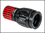
マウント付きLED M365LP1に取り付けられたアダプタSM2F
- 当社のマウント付きLEDへのØ25 mm~Ø25.4 mm(Ø1インチ)またはØ50 mm~Ø50.8 mm(Ø2インチ)コリメート用光学素子の取付け
- レンズ位置はロック用止めネジ付き回転リングで調整および固定
- ARコーティング付きレンズの有無は選択可能(詳細は下表参照)
- 当社のSM2ネジ付き顕微鏡ポート用アダプタに対応
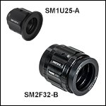
こちらのアダプタを使用すると、Ø25 mm~Ø25.4 mm(Ø1インチ)またはØ50 mm~Ø50.8 mm(Ø2インチ)のコリメート用光学素子を上記のマウント付きLEDに取り付けることができます。このアダプタはØ25 mm~Ø25.4 mm(Ø1インチ)レンズを11 mm、Ø50 mm~Ø50.8 mm(Ø2インチ)レンズを20 mmの範囲で移動できます。コリメート用光学素子が付属しない製品と、取り外し可能な350~700 nmまたは650~1050 nm のARコーティング付き非球面コンデンサーレンズが付属した製品をご用意しております。こちらのアダプタはすべてSM1外ネジでLEDの筐体に取りけられるため、Ø30.5 mmとØ57.0 mmのどちらの筐体にもご使用いただけます。
コリメート用レンズは内部キャリッジに取り付けられ、ローレット付き調整リング(型番の刻印付き、左の写真参照)を回すと、Z軸に沿って無伸縮で移動します。レンズの位置を固定するときは、調整リング横の固定ネジを2 mm六角レンチで回します。筐体に刻印されている2 mm間隔の線は、キャリッジの移動距離の目安となります。こちらのコリメートアダプタでは、非球面コンデンサーレンズを保持するために、標準品よりも厚いSM1またはSM2ネジ付き固定リングが使用されています。固定リングの操作にはスパナレンチSPW602(SM1固定リング用)またはSPW604(SM2固定リング用)を使用します。
入射側および出射側の開口部にあるネジはレンズを移動するときも固定されているため、これらのアダプタは固定されたレンズチューブの間に取り付けることも可能です。この開口部のネジを用いて様々な部品が取り付けられます。詳細は下の表をご覧ください。
光学素子の取り付け・取り外し
コリメートアダプタに光学素子の取り付けや取り外しをするときは、まず内部キャリッジを調整リングで筐体の出射側の端まで移動させてください。次に、スパナレンチで付属の固定リングを外します。すでにレンズが取り付けてある場合には、レンズをキャリッジから取り外します。キャリッジに別のØ25 mm~Ø25.4 mm(Ø1インチ)またはØ50 mm~Ø50.8 mm(Ø2インチ)光学素子を挿入し、固定リングで固定します。
使用するLEDの波長が透過しない素材やARコーティングのレンズを使用することは推奨しません。波長が340 nm以下の深紫外LEDにはUV溶融石英(UVFS)製のレンズが必要です。多くの一般的なガラスでは350 nm以下の光は透過しません。 波長が1050 nm以上の赤外LEDのコリメートには、380~2100 nmで使用可能なØ50 mmのACL50832Uなど、コーティング無しのコンデンサーレンズをご使用いただけます。
| Item # | Compatible Optic | Lens Travel Range | Input Threading | Output Threading | Included Lens | AR Coating Range | Lens Focal Length | Operating Temperature | Diagram |
|---|---|---|---|---|---|---|---|---|---|
| SM1Ua | Ø1" (Ø25 mm) | 11 mm (0.43") | External SM1 (1.035"-40) | Internal SM2 (2.035"-40)b | N/A | N/A | N/A | 15 - 60 °C (Non-Condensing) | |
| SM1U25-A | ACL2520U-A | 350 - 700 nm | 20.1 mm | ||||||
| SM1U25-B | ACL2520U-B | 650 - 1050 nm | 20.1 mm | ||||||
| SM2Fa | Ø2" (Ø50 mm) | 20 mm (0.79") | External SM1 (1.035"-40)c | Internal SM2 (2.035"-40)d | N/A | N/A | N/A | ||
| SM2F32-A | ACL50832U-A | 350 - 700 nm | 32.0 mm | ||||||
| SM2F32-B | ACL50832U-B | 650 - 1050 nm | 32.0 mm |

| LED Quick Links |
|---|
| Mounted LEDs |
| Deep UV (265 - 340 nm) |
| UV (365 - 405 nm) |
| Cold Visible (415 - 565 nm) |
| Warm Visible (590 - 730 nm) |
| IR (780 - 1900 nm) |
| Mid-IR (3400 - 5200 nm) |
| Purple (455 nm / 640 nm) |
| White (400 - 700 nm) |
| Broadband Mounted LEDs |
| LED Collimationa |
| Adjustable Collimation Adapters |
| Microscope Collimation Adapters |
| LED Mating Connector |
| LED Drivers |
Click for Details
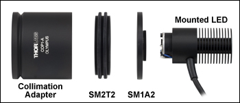
コリメートアダプタは、ネジアダプタSM2T2およびSM1A2を用いてLEDに取り付けます。同じセットアップでØ57.0 mm筐体の付いたLED(上記参照)に取り付けることも可能です。
- 小さいf値(約0.8)のARコーティング付き非球面レンズ
- Leica、Nikon、Olympus、Zeiss社製の一部の顕微鏡に対応
- ビームのコリメート・集光の調整が容易
- 上記LEDに使用する場合にはカプラSM2T2およびアダプタSM1A2(いずれも別売り)が必要
マウント付きLED(上記参照)の出力光のコリメート用として、Ø50 mmのARコーティング付き非球面コンデンサーレンズ(EFL:40mm)を取り付けた、コリメート用アダプタをご用意しております。ARコーティングは2種類(350~700 nm、650~1050 nm)、筐体は4種類ございます。筐体はOlympus*、Leica、Nikon、Zeiss社製の一部の顕微鏡の照明ポートに適合するよう、アリ溝またはバヨネットマウントが付いています。対応可能な顕微鏡については下表をご覧ください。
使用するLEDの波長が透過しない素材やARコーティングを有するアダプタを使用することは推奨しません。深紫外域LEDにはUV溶融石英(UVFS)製のレンズが必要です。多くの一般的なガラスでは350 nm以下の光は透過しません。 1050 nm以上の赤外域LEDは、コーティング無しのコンデンサーレンズを使用してコリメートが可能です。 ACL5040Uは下記のコリメーターパッケージに使用されているコーティング無しのØ50 mmレンズで、380~2100 nmの波長範囲で使用できます。365~1650 nmのLEDにご使用いただけるその他のコリメータについては、上の各製品の表内の青いinfoアイコンをクリックし、「Collimation Adapter」タブをご覧ください。
上記のLED光源は、上の写真のように、カプラSM2T2およびアダプタSM1A2(いずれも付属していません)を用いてコリメータに取り付けられます。このアセンブリは、LED筐体を外して他のLED光源に簡単に付け変えることができます。
*BXおよびIX顕微鏡の透過ランプハウスポートの光学設計により、Olympus社のアダプタを別途ご購入いただくことが必要な場合があります。
| Collimation Adapter Selection Guide | |||||||
|---|---|---|---|---|---|---|---|
| Compatible Microscopes | Olympus BX & IXa | Leica DMI | Zeiss Axioskop & Examinerb | Nikon Eclipse Ti | |||
| AR Coating Range of Condenser Lens | Lens Focal Length | Lens Item # |  Click to Enlarge |  Click to Enlarge |  Click to Enlarge |  Click to Enlarge | |
| 350 - 700 nm | 40.0 mm | ACL5040U-A | COP1-A | COP2-A | COP4-A | COP5-A | |
| 650 - 1050 nm | 40.0 mm | ACL5040U-B | COP1-B | COP2-B | COP4-B | COP5-B | |

- 4ピンメスPico型(M8)レセプタクル
- マウント付きLEDの電源ケーブル接続用M8 x 1ネジ
- パネル取付け用M8 x 0.5ネジ、カスタム筐体用
- 長さ0.5 mのAWG24ケーブル
- IP 67およびNEMA 6P規格準拠
コネクタCON8ML-4をご使用いただくことで、お手持ちの電源を当社のマウント付きLEDに接続することができます。当社では4ピンオス型M8接続ケーブル(型番CAB-LEDD1)もご用意しております。
| Pin | Color | Specification | 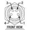 |
|---|---|---|---|
| 1 | Brown | LED Anode | |
| 2 | White | LED Cathode | |
| 3 | Black | EEPROM GND | |
| 4 | Blue | EEPROM IO |

マウント付きLEDの4ピンM8プラグに接続しているCON8ML-4
 Products Home


 ズーム
ズーム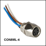
 マウント付きLED