大径ビーム用2軸走査型ガルバノミラーシステム

- For Beam Diameters up to 10 mm
- Choice of Dielectric or Metallic Mirror Coating
- Easy Integration into OEM Systems
- Analog Control Electronics
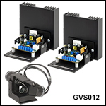
GVS012
Galvo Scanning System
with Silver-Coated Mirrors
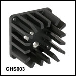
GHS003
Heatsink
GVS112
Dual-Axis Motor/Mirror Assembly
with Gold-Coated Mirrors
(Drivers Not Shown)

Please Wait
| Key Specificationsa,b | |
|---|---|
| Beam Diameter | 10 mm (Max) |
| Input/Output Vertical Beam Offsetc | 14.7 mm (0.58") |
| Repeatability | 15 µrad |
| Linearity (50% Full Travel) | 99.9% |
| Max Mechanical Scan Angle | ±20.0° (w/ 0.5 V/deg Scaling) |
| Bandwidth (Full Travel) | 25 Hz Square Wave 35 Hz Sine Wave |
| Bandwidth (50% Full Travel) | 65 Hz Square Wave 130 Hz Sine Wave |
| Small Angle (±0.2°) Bandwidth | 1 kHz |
| Small Angle Step Responsed | 400 µs |
| Analog Position Signal Input Range | ±10 V |
| Mechanical Position Signal Input Scale Factore | 1.0 V, 0.8 V, or 0.5 V per degree |
| Position Sensor Output | 40 to 80 µA |
特長
- 可動マグネットモータ設計により高速応答が可能(400 µs for ±0.2°)
- 高精度(15 µrad)ミラー位置検出
- 電流ダンピングとエラーリミッタ付きアナログPD制御回路
- ミラーコーティングが選択可能(下表参照)
これらの高速走査型ガルバノミラーシステムは、10 mmまでのビーム径のカスタム仕様のレーザービームステアリングシステムやお客様の製品に組み込むために設計されています。 各システムには2軸ガルバノモータおよびミラーアセンブリ、関連ドライバーボード、ドライバーボードヒートシンクが含まれています。 さらにこの製品にはベースプレートが付属しており、組み付けられた状態でØ12 mm~Ø12.7 mm(1/2インチ)ポスト用アダプタおよびチルトプラットフォーム用アダプタとして使用できます。 低ノイズのリニア電源(GPS011から始まる型番)、ガルバノドライバーボード用カバー(GCE001)、ケージアダプタ(GCM012/M)、ヒートシンク(GHS003/M)も別途ご用意しています。詳細は下記をご参照ください。また、本システムを駆動するためには、ファンクションジェネレータやDAQカードなどのアナログ信号用電源が別途必要です。詳細についてはマニュアルのChapter 3と4をご覧ください。
各ガルバノシステムにはモータ駆動用ケーブルが付属しており、それでドライバーボードとモータを接続します。この長さ30 cmのケーブルは、ドライバーボードとモータの内部センサの両方に対して特別に校正されています。お手持ちのケーブルを取り付けて校正することはお勧めしません。カスタム仕様のガルバノシステムをご希望の場合は当社までご連絡ください。
ミラーは下表のように5つのコーティングからお選びいただけます。
ガルバノモータ/ミラーアセンブリ
当社のガルバノシステムは、シャフト上に光学ミラーが取り付けられたガルバノメーターベースの走査型モータと制御ボードに位置フィードバックを送るディテクタで構成されています。 ガルバノメーターモータでは、静止型マグネットや回転式コイル設計ではなく可動マグネット設計を採用し、最速の応答時間と最高の共振周波数をご提供できます。 ミラー位置は、モータ筐体内にある光学センシングシステムを使ってエンコードされます。
回転シャフトの角加速度が大きいので、ミラーのサイズや形状、慣性モーメントは高性能ガルバノシステム設計において重要な要素となります。 また、加速度が大きくなってもミラーは平面性を維持する必要があります。 ガルバノモータの特性に合わせてシステムの性能を最大限に高めるために、当社のガルバノシステムでは、これらの要素は全て最適化されています。
ガルバノミラーはフレクシャークランプによってモータ/ミラーアセンブリに固定されます。ミラーホルダの位置は工場からの出荷時に正しい位置に設定されていますので、お客様による変更はなさらないでください。
Click to Enlarge
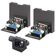
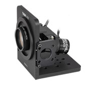
ガルバノミラーアセンブリ、銀コーティングミラーGVS012とドライバーボード
走査型ガルバノミラーシステムおよびドライバーボード
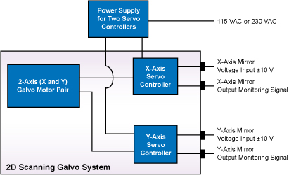
当社の走査型ガルバノミラーシステムには、全て1軸もしくは2軸のミラー/モーターアセンブリまたはドライバーボードが付属します。右図は銀コーティング、10 mm の2次元ガルバノミラーおよび2つのドライバーボードです。 ミラーアセンブリには、複数の取付け穴およびミラー/モータ用の回転式カラーマウントがあります。 フライングリードでドライバーボードに接続できます。 他の取付けオプションやアクセサリについては下記をご参照ください。
サーボドライバーボード
比例微分(PD)フィードバック制御サーボドライバ回路は、モータ内部の光学的な位置検出システムからの信号を処理し、指定した位置までミラーを回転させるのに必要な駆動電圧を供給します。 スキャナはベクトル位置決め(レーザーマーキング等)、ラスタ位置決め(プリンタや走査型レーザ顕微鏡)や、ステップ制御用途に適したClass 0のNon-Integratingサーボモータを使用しています。 また、PDコントローラによって優れた動的性能を備えています。回路には高い加速度でも安定性を維持できる電流モジュールが付いています。 なお、当社のガルバノシステムでは、全て同じドライバーボードが使用されています。
システムの操作
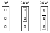
サーボドライバはDC電源、ガルバノモータ、入力電圧源に接続する必要があります(モニタ接続はオプションです)。連続走査用途については、ガルバノミラーを全ての範囲で走査するには、矩形波または正弦波出力のファンクションジェネレータで十分です。 さらに複雑なパターンを走査するには、DAQカードなどのプログラム可能な電圧源をご使用いただけます。なお、これらのシステムにはファンクションジェネレータやDAQカードは付属おりませんのでご注意ください。入力電圧とミラーの位置の間の比率は 0.5 V/°、0.8 V/°、1 V/°に切り替えることができます。これらのシステムでは、その比を0.5に設定した時、±10 Vの入力電圧に対して最大走査角度である±20°回転させることができます。 制御回路は、ミラーの位置のトラッキングに必要なモニタ出力も提供します。 また、駆動電流に比例した電圧もモータに供給され、コマンド位置と実際のミラー位置の差も制御回路によって提供されます。
閉ループミラー位置決め
ミラーの角度方向(位置)は、ガルバノメータ筐体内部に組み込まれた容量型センシングシステムを使って測定されています。 それによりガルバノミラーの方向を閉ループ動作で安定化させることが可能になります。
ガルバノミラーシステムでは、矩形波の入力信号を使用した場合は、最大走査角度(±20°)で65 Hzのスキャンが可能で、正弦波を使用した場合は130 Hzのスキャンが可能です。±0.2°の小角ステップに対しての応答時間は400 µsです。 最大走査周波数は 1kHzで、角度分解能は0.0008°(GPS011シリーズリニア電源では15 μrad)です。
走査レンズ用取付けブラケット
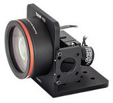
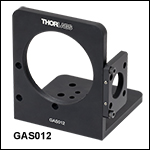
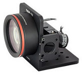
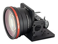
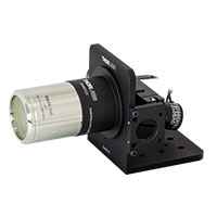
2軸大径ガルバノミラーは、別売りの取付けブラケットGAS012とお使いいただけます(別売り。下記参照)。このブラケットをお使いいただくと、当社のFシータ(θ)もしくはテレセントリック走査レンズと一緒に取り付けることができます(右図参照)。 完成したアセンブリは、標準のブレッドボードもしくは光学テーブル上の光学系に簡単に組み込むことができます。
ガルバノメーターシステムの仕様a
| Item # | GVS212(/M) | GVS012(/M) | GVS112(/M) | |
|---|---|---|---|---|
| Mirror | ||||
| Maximum Beam Diameter | 10 mm | |||
| Input/Output Vertical Beam Offsetb | 14.7 mm (0.58") | |||
| Substrate | Quartz | |||
| Coating | Broadband Dielectric (-E02) | Protected Silver | Protected Gold | |
| Wavelength Range | 400 - 750 nm | 500 nm - 2.0 µm | 800 nm - 20 µm | |
| Damage Thresholds | 0.25 J/cm2 at 532 nm (10 ns, 10 Hz, Ø0.803 mm) | 3 J/cm2 at 1064 nm (10 ns, 10 Hz, Ø1.000 mm) | 2 J/cm2 at 1064 nm (10 ns, 10 Hz, Ø1.000 mm) | |
| Parallelism | < 3 arcmin | |||
| Surface Quality | 40-20 Scratch-Dig | |||
| Front Surface Flatness (@633 nm) | λ | |||
| Clear Aperture | > 90% of Dimension | |||
| Motor and Position Sensor | ||||
| Linearity (50% Full Travel) | 99.9% | |||
| Scale Driftc | < 200 ppm/°C (Max) | |||
| Zero Driftc | < 20 μrad/°C (Max) | |||
| Repeatability | 15 μrad | |||
| Resolution (Mechanical) | With GPS011 Linear Power Supply: 0.0008° (15 µrad) With Standard Switching Mode Power Supply: 0.004° (70 µrad) | |||
| Average Current | 1 A | |||
| Peak Current | 10 A | |||
| Maximum Scan Angle (Mechanical Angle) | ±20.0° (Input Scale Factor 0.5 V per degree) | |||
| Motor Weight (Including Cables, Excluding Brackets) | 94 g | |||
| Operating Temperature Range | 15 to 35 °C | |||
| Position Sensor Output Range | 40 to 80 µA | |||
| Drive Electronics | ||||
| Full Travel Bandwidthd | 25 Hz Square-Wave, 35 Hz Sine Wave | |||
| Full Scale Bandwidth | 65 Hz Square Wave, 130 Hz Sine Wave | |||
| Small Angle (±0.2°) Bandwidth | 1 kHz | |||
| Small Angle Step Responsee | 400 µs | |||
| Power Supply | ±15 to ±18 VDC (1.25 A rms, 10 A Peak Max) | |||
| Analog Signal Input Resistance | 20 kΩ ± 1% (Differential Input) | |||
| Position Signal Output Resistance | 1 kΩ ± 1% | |||
| Analog Position Signal Input Range | ±10 V | |||
| Mechanical Position Signal Input Scale Factorf | Switchable: 1.0 V, 0.8 V or 0.5 V per degree | |||
| Mechanical Position Signal Output Scale Factor | 0.5 V per degree | |||
| Operating Temperature Range | 15 to 35 °C | |||
| Servo Board Size (W x D x H) | 85 mm x 74 mm x 44 mm (3.35" x 2.9" x 1.73") | |||
推奨最大スキャン角度
| Input Beam Diameter | Max Optical Scan Angle (Beam Angle) | Mechanical Scan Angle (Motor Angle) | ||
|---|---|---|---|---|
| X Axis | Y Axis | X Axis | Y Axis | |
| 10 mm | ±17° | +10° / -26° | ±8.5° | +5° / -13° |
| 8 mm | ±20° | ±30° | ±10° | ±15° |
| 6 mm | ±23° | +40° / -35° | ±11.5° | +20° / -17.5° |
| 4 mm | ±27° | ±40° | ±13.5° | ±20° |
| 2 mm | ±31° | ±40° | ±15.5° | ±20° |
Power Supply Specifications
| Item # | GPS011-US | GPS011-EC | GPS011-JP |
|---|---|---|---|
| Input Voltage | 115 VAC, 60 Hz | 230 VAC, 50 Hz | 100 VAC, 50/60 Hz |
| Output Voltage | ±15 VDC, 3.0 A / 0.1 A, 1.4/6.3 ms | ||
| Fuses | T2.0 A Anti-Surge Ceramic | T1.0 A Anti-Surge Ceramic | T2.5 A Anti-Surge Ceramic |
| Dimensions | 179 mm x 274 mm (Max) x 122 mm (7.05" x 10.79" (Max) x 4.8") | ||
| Weight | 4.73 kg (10.4 lbs) | ||
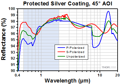
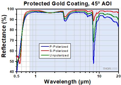
下の曲線は、ガルバノシステムGVSシリーズに付属するコーティング付きミラーの反射率データです。網掛けの部分は、各コーティングの推奨使用範囲を示しています。この帯域外(特に反射率が上下したり傾斜したりしている範囲)での反射率は品質管理の面で厳密にモニタされたものではなく、ロット毎にもバラツキがある可能性がありますのでご注意ください。
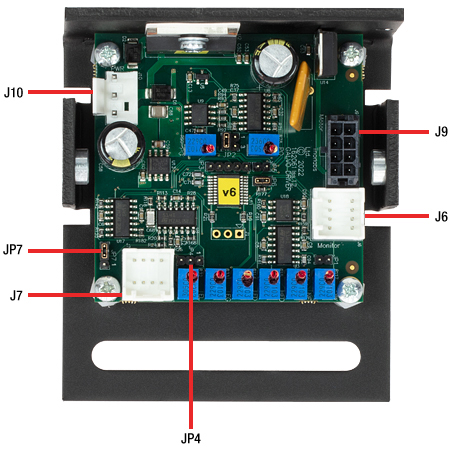
ここではGVSシリーズドライバーボードの電源用コネクタ、診断用コネクタ、モータ用コネクタ、コマンド入力用コネクタについての情報をご紹介しています。
GVSシリーズドライバの接続部
Click to Enlarge
PCBコネクタの全体図。 各コネクタの詳細は下でご覧いただけます。
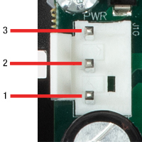
J10:電源用コネクタ
| Pin | Designation |
|---|---|
| 1 | + 15 V |
| 2 | Ground |
| 3 | - 15 V |
J6:診断用コネクタ
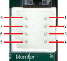
| Pin | Designation |
|---|---|
| 1 | Scanner Position |
| 2 | Internal Command Signal |
| 3 | Positioning Error x 5 |
| 4 | Motor Drive Current |
| 5 | Not Connected |
| 6 | Test Input (NC) |
| 7 | Motor + Coil Voltage / 2 |
| 8 | Ground |
J9:モータ用コネクタ
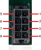
| Pin | Designation |
|---|---|
| 1 | Position Sensor A Current |
| 2 | Position Sensor Ground |
| 3 | Position Sensor Cable Shield |
| 4 | Drive Cable Shield |
| 5 | Position Sensor B Current |
| 6 | Position Sensor Power |
| 7 | Motor + Coil |
| 8 | Motor - Coil |
J7:コマンド入力用コネクタ
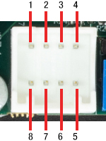
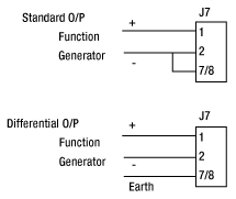
| Pin | Designation |
|---|---|
| 1 | Command Input +ve |
| 2 | Command Input -ve |
| 3 | DRV OK |
| 4 | External Enable |
| 5 | -12 V Output (Low Impedance O/P) |
| 6 | +12 V Output (Low Impedance O/P) |
| 7 | Ground |
| 8 | Ground |
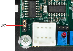
JP7:電圧/角度の変換係数調整
ドライバーボードの外部からのENABLE化
JP4のピン2と3にジャンパをセットすることで、ドライブ回路を外部からENABL化できるようになります。

JP4
そうしておくと、J7のピン4に5 V CMOS信号を送信することでドライブ回路のENABLE/DISABLEを制御できます。
J7のピン4でロジック・ハイの信号を受信するか、または何も信号が無い場合は、ドライブ回路はENABLEになります。一方、ロジック・ローの信号を受信すると、ドライブ回路はDISABLEになります。
| Pin | Designation |
|---|---|
| 1 | Command Input +ve |
| 2 | Command Input -ve |
| 3 | No Connect |
| 4 | External Enable |
| 5 | -12 V Output |
| 6 | +12 V Output |
| 7 | Ground |
| 8 | Ground |

J7
| Damage Threshold Specifications | |
|---|---|
| Item # | Damage Threshold |
| GVS012(/M) | 3 J/cm2 at 1064 nm (10 ns, 10 Hz, Ø1.000 mm) |
| GVS112(/M) | 2 J/cm2 at 1064 nm (10 ns, 10 Hz, Ø1.000 mm) |
| GVS212(/M) | 0.25 J/cm2 at 532 nm (10 ns, 10 Hz, Ø0.803 mm) |
当社の大径ビーム用走査型ガルバノミラーの損傷閾値データ
右の仕様は、当社の大型ビーム用走査型ガルバノミラーの測定値です。損傷閾値の仕様はすべての大径ビーム用走査型ガルバノミラーシステムで同じです。
レーザによる損傷閾値について
このチュートリアルでは、レーザ損傷閾値がどのように測定され、使用する用途に適切な光学素子の決定にその値をどのようにご利用いただけるかを総括しています。お客様のアプリケーションにおいて、光学素子を選択する際、光学素子のレーザによる損傷閾値(Laser Induced Damage Threshold :LIDT)を知ることが重要です。光学素子のLIDTはお客様が使用するレーザの種類に大きく依存します。連続(CW)レーザは、通常、吸収(コーティングまたは基板における)によって発生する熱によって損傷を引き起こします。一方、パルスレーザは熱的損傷が起こる前に、光学素子の格子構造から電子が引き剥がされることによって損傷を受けます。ここで示すガイドラインは、室温で新品の光学素子を前提としています(つまり、スクラッチ&ディグ仕様内、表面の汚染がないなど)。光学素子の表面に塵などの粒子が付くと、低い閾値で損傷を受ける可能性があります。そのため、光学素子の表面をきれいで埃のない状態に保つことをお勧めします。光学素子のクリーニングについては「光学素子クリーニングチュートリアル」をご参照ください。
テスト方法
当社のLIDTテストは、ISO/DIS 11254およびISO 21254に準拠しています。
初めに、低パワー/エネルギのビームを光学素子に入射します。その光学素子の10ヶ所に1回ずつ、設定した時間(CW)またはパルス数(決められたprf)、レーザを照射します。レーザを照射した後、倍率約100倍の顕微鏡を用いた検査で確認し、すべての確認できる損傷を調べます。特定のパワー/エネルギで損傷のあった場所の数を記録します。次に、そのパワー/エネルギを増やすか減らすかして、光学素子にさらに10ヶ所レーザを照射します。このプロセスを損傷が観測されるまで繰返します。損傷閾値は、光学素子が損傷に耐える、損傷が起こらない最大のパワー/エネルギになります。1つのミラーBB1-E02の試験結果は以下のようなヒストグラムになります。
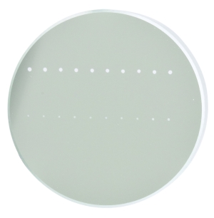
上の写真はアルミニウムをコーティングしたミラーでLIDTテストを終えたものです。このテストは、損傷を受ける前のレーザのエネルギは0.43 J/cm2 (1064 nm、10 ns pulse、 10 Hz、Ø1.000 mm)でした。
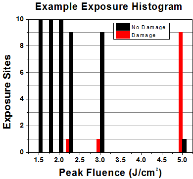
| Example Test Data | |||
|---|---|---|---|
| Fluence | # of Tested Locations | Locations with Damage | Locations Without Damage |
| 1.50 J/cm2 | 10 | 0 | 10 |
| 1.75 J/cm2 | 10 | 0 | 10 |
| 2.00 J/cm2 | 10 | 0 | 10 |
| 2.25 J/cm2 | 10 | 1 | 9 |
| 3.00 J/cm2 | 10 | 1 | 9 |
| 5.00 J/cm2 | 10 | 9 | 1 |
試験結果によれば、ミラーの損傷閾値は 2.00 J/cm2 (532 nm、10 ns pulse、10 Hz、 Ø0.803 mm)でした。尚、汚れや汚染によって光学素子の損傷閾値は大幅に低減されるため、こちらの試験はクリーンな光学素子で行っています。また、特定のロットのコーティングに対してのみ試験を行った結果ではありますが、当社の損傷閾値の仕様は様々な因子を考慮して、実測した値よりも低めに設定されており、全てのコーティングロットに対して適用されています。
CWレーザと長パルスレーザ
光学素子がCWレーザによって損傷を受けるのは、通常バルク材料がレーザのエネルギを吸収することによって引き起こされる溶解、あるいはAR(反射防止)コーティングのダメージによるものです[1]。1 µsを超える長いパルスレーザについてLIDTを論じる時は、CWレーザと同様に扱うことができます。
パルス長が1 nsと1 µs の間のときは、損傷は吸収、もしくは絶縁破壊のどちらかで発生していると考えることができます(CWとパルスのLIDT両方を調べなければなりません)。吸収は光学素子の固有特性によるものか、表面の不均一性によるものかのどちらかによって起こります。従って、LIDTは製造元の仕様以上の表面の質を有する光学素子にのみ有効です。多くの光学素子は、ハイパワーCWレーザで扱うことができる一方、アクロマティック複レンズのような接合レンズやNDフィルタのような高吸収光学素子は低いCWレーザ損傷閾値になる傾向にあります。このような低い損傷閾値は接着剤や金属コーティングにおける吸収や散乱によるものです。
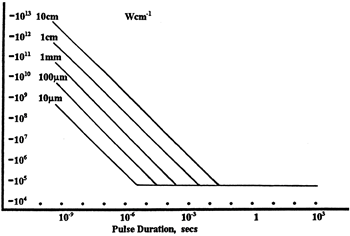
線形パワー密度におけるLIDTに対するパルス長とスポットサイズ。長パルス~CWでは線形パワー密度はスポットサイズにかかわらず一定です。 このグラフの出典は[1]です。
繰返し周波数(prf)の高いパルスレーザは、光学素子に熱的損傷も引き起こします。この場合は吸収や熱拡散率のような因子が深く関係しており、残念ながらprfの高いレーザが熱的影響によって光学素子に損傷を引き起こす場合の信頼性のあるLIDTを求める方法は確立されておりません。prfの大きいビームでは、平均出力およびピークパワーの両方を等しいCW出力と比較する必要があります。また、非常に透過率の高い材料では、prfが上昇してもLIDTの減少は皆無かそれに近くなります。
ある光学素子の固有のCWレーザの損傷閾値を使う場合には、以下のことを知る必要があります。
- レーザの波長
- ビーム径(1/e2)
- ビームのおおよその強度プロファイル(ガウシアン型など)
- レーザのパワー密度(トータルパワーをビームの強度が1/e2の範囲の面積で割ったもの)
ビームのパワー密度はW/cmの単位で計算します。この条件下では、出力密度はスポットサイズとは無関係になります。つまり、スポットサイズの変化に合わせてLIDTを計算し直す必要がありません(右グラフ参照)。平均線形パワー密度は、下の計算式で算出できます。

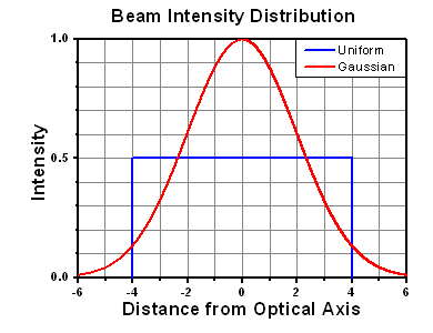
ここでは、ビーム強度プロファイルは一定であると仮定しています。次に、ビームがホットスポット、または他の不均一な強度プロファイルの場合を考慮して、おおよその最大パワー密度を計算する必要があります。ご参考までに、ガウシアンビームのときはビームの強度が1/e2の2倍のパワー密度を有します(右下図参照)。
次に、光学素子のLIDTの仕様の最大パワー密度を比較しましょう。損傷閾値の測定波長が光学素子に使用する波長と異なっている場合には、その損傷閾値は適宜補正が必要です。おおよその目安として参考にできるのは、損傷閾値は波長に対して比例関係であるということです。短い波長で使う場合、損傷閾値は低下します(つまり、1310 nmで10 W/cmのLIDTならば、655 nmでは5 W/cmと見積もります)。

この目安は一般的な傾向ですが、LIDTと波長の関係を定量的に示すものではありません。例えば、CW用途では、損傷はコーティングや基板の吸収によってより大きく変化し、必ずしも一般的な傾向通りとはなりません。上記の傾向はLIDT値の目安として参考にしていただけますが、LIDTの仕様波長と異なる場合には当社までお問い合わせください。パワー密度が光学素子の補正済みLIDTよりも小さい場合、この光学素子は目的の用途にご使用いただけます。
当社のウェブ上の損傷閾値の仕様と我々が行った実際の実験の値の間にはある程度の差があります。これはロット間の違いによって発生する誤差を許容するためです。ご要求に応じて、当社は個別の情報やテスト結果の証明書を発行することもできます。損傷解析は、類似した光学素子を用いて行います(お客様の光学素子には損傷は与えません)。試験の費用や所要時間などの詳細は、当社までお問い合わせください。
パルスレーザ
先に述べたように、通常、パルスレーザはCWレーザとは異なるタイプの損傷を光学素子に引き起こします。パルスレーザは損傷を与えるほど光学素子を加熱しませんが、光学素子から電子をひきはがします。残念ながら、お客様のレーザに対して光学素子のLIDTの仕様を照らし合わせることは非常に困難です。パルスレーザのパルス幅に起因する光学素子の損傷には、複数の形態があります。以下の表中のハイライトされた列は当社の仕様のLIDT値が当てはまるパルス幅に対する概要です。
パルス幅が10-9 sより短いパルスについては、当社の仕様のLIDT値と比較することは困難です。この超短パルスでは、多光子アバランシェ電離などのさまざまなメカニクスが損傷機構の主流になります[2]。対照的に、パルス幅が10-7 sと10-4 sの間のパルスは絶縁破壊、または熱的影響により光学素子の損傷を引き起こすと考えられます。これは、光学素子がお客様の用途に適しているかどうかを決定するために、レーザービームに対してCWとパルス両方による損傷閾値を参照しなくてはならないということです。
| Pulse Duration | t < 10-9 s | 10-9 < t < 10-7 s | 10-7 < t < 10-4 s | t > 10-4 s |
|---|---|---|---|---|
| Damage Mechanism | Avalanche Ionization | Dielectric Breakdown | Dielectric Breakdown or Thermal | Thermal |
| Relevant Damage Specification | No Comparison (See Above) | Pulsed | Pulsed and CW | CW |
お客様のパルスレーザに対してLIDTを比較する際は、以下のことを確認いただくことが重要です。
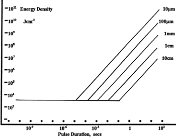
エネルギ密度におけるLIDTに対するパルス長&スポットサイズ。短パルスでは、エネルギ密度はスポットサイズにかかわらず一定です。このグラフの出典は[1]です。
- レーザの波長
- ビームのエネルギ密度(トータルエネルギをビームの強度が1/e2の範囲の面積で割ったもの)
- レーザのパルス幅
- パルスの繰返周波数(prf)
- 実際に使用するビーム径(1/e2 )
- ビームのおおよその強度プロファイル(ガウシアン型など)
ビームのエネルギ密度はJ/cm2の単位で計算します。右のグラフは、短パルス光源には、エネルギ密度が適した測定量であることを示しています。この条件下では、エネルギ密度はスポットサイズとは無関係になります。つまり、スポットサイズの変化に合わせてLIDTを計算し直す必要がありません。ここでは、ビーム強度プロファイルは一定であると仮定しています。ここで、ビームがホットスポット、または他の不均一な強度プロファイルの場合を考慮して、おおよその最大パワー密度を計算する必要があります。ご参考までに、ガウシアンビームのときは一般にビームの強度が1/e2のときの2倍のパワー密度を有します。
次に、光学素子のLIDTの仕様と最大エネルギ密度を比較しましょう。損傷閾値の測定波長が光学素子に使用する波長と異なっている場合には、その損傷閾値は適宜補正が必要です[3]。経験則から、損傷閾値は波長に対して以下のような平方根の関係であるということです。短い波長で使う場合、損傷閾値は低下します(例えば、1064 nmで 1 J/cm2のLIDTならば、532 nmでは0.7 J/cm2と計算されます)。

波長を補正したエネルギ密度を得ました。これを以下のステップで使用します。
ビーム径は損傷閾値を比較する時にも重要です。LIDTがJ/cm2の単位で表される場合、スポットサイズとは無関係になりますが、ビームサイズが大きい場合、LIDTの不一致を引き起こす原因でもある不具合が、より明らかになる傾向があります[4]。ここで示されているデータでは、LIDTの測定には<1 mmのビーム径が用いられています。ビーム径が5 mmよりも大きい場合、前述のようにビームのサイズが大きいほど不具合の影響が大きくなるため、LIDT (J/cm2)はビーム径とは無関係にはなりません。
次に、パルス幅について補正します。パルス幅が長くなるほど、より大きなエネルギに光学素子は耐えることができます。パルス幅が1~100 nsの場合の近似式は以下のようになります。

お客様のレーザのパルス幅をもとに、光学素子の補正されたLIDTを計算するのにこの計算式を使います。お客様の最大エネルギ密度が、この補正したエネルギ密度よりも小さい場合、その光学素子はお客様の用途でご使用いただけます。ご注意いただきたい点は、10-9 s と10-7 sの間のパルスにのみこの計算が使えることです。パルス幅が10-7 sと10-4 sの間の場合には、CWのLIDTも調べなければなりません。
当社のウェブ上の損傷閾値の仕様と我々が行った実際の実験の値の間にはある程度の差があります。これはロット間の違いによって発生する誤差を許容するためです。ご要求に応じて、当社では個別のテスト情報やテスト結果の証明書を発行することも可能です。詳細は、当社までお問い合わせください。
[1] R. M. Wood, Optics and Laser Tech. 29, 517 (1998).
[2] Roger M. Wood, Laser-Induced Damage of Optical Materials (Institute of Physics Publishing, Philadelphia, PA, 2003).
[3] C. W. Carr et al., Phys. Rev. Lett. 91, 127402 (2003).
[4] N. Bloembergen, Appl. Opt. 12, 661 (1973).
レーザーシステムが光学素子に損傷を引き起こすかどうか判断するプロセスを説明するために、レーザによって引き起こされる損傷閾値(LIDT)の計算例をいくつかご紹介します。同様の計算を実行したい場合には、右のボタンをクリックしてください。計算ができるスプレッドシートをダウンロードいただけます。ご使用の際には光学素子のLIDTの値と、レーザーシステムの関連パラメータを緑の枠内に入力してください。スプレッドシートでCWならびにパルスの線形パワー密度、ならびにパルスのエネルギ密度を計算できます。これらの値はスケーリング則に基づいて、光学素子のLIDTの調整スケール値を計算するのに用いられます。計算式はガウシアンビームのプロファイルを想定しているため、ほかのビーム形状(均一ビームなど)には補正係数を導入する必要があります。 LIDTのスケーリング則は経験則に基づいていますので、確度は保証されません。なお、光学素子やコーティングに吸収があると、スペクトル領域によってLIDTが著しく低くなる場合があります。LIDTはパルス幅が1ナノ秒(ns)未満の超短パルスには有効ではありません。
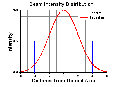
ガウシアンビームの最大強度は均一ビームの約2倍です。
CWレーザの例
波長1319 nm、ビーム径(1/e2)10 mm、パワー0.5 Wのガウシアンビームを生成するCWレーザーシステム想定します。このビームの平均線形パワー密度は、全パワーをビーム径で単純に割ると0.5 W/cmとなります。

しかし、ガウシアンビームの最大パワー密度は均一ビームの約2倍です(右のグラフ参照)。従って、システムのより正確な最大線形パワー密度は1 W/cmとなります。
アクロマティック複レンズAC127-030-CのCW LIDTは、1550 nmでテストされて350 W/cmとされています。CWの損傷閾値は通常レーザ光源の波長に直接スケーリングするため、LIDTの調整値は以下のように求められます。

LIDTの調整値は350 W/cm x (1319 nm / 1550 nm) = 298 W/cmと得られ、計算したレーザーシステムのパワー密度よりも大幅に高いため、この複レンズをこの用途に使用しても安全です。
ナノ秒パルスレーザの例:パルス幅が異なる場合のスケーリング
出力が繰返し周波数10 Hz、波長355 nm、エネルギ1 J、パルス幅2 ns、ビーム径(1/e2)1.9 cmのガウシアンビームであるNd:YAGパルスレーザーシステムを想定します。各パルスの平均エネルギ密度は、パルスエネルギをビームの断面積で割って求めます。

上で説明したように、ガウシアンビームの最大エネルギ密度は平均エネルギ密度の約2倍です。よって、このビームの最大エネルギ密度は約0.7 J/cm2です。
このビームのエネルギ密度を、広帯域誘電体ミラーBB1-E01のLIDT 1 J/cm2、そしてNd:YAGレーザーラインミラーNB1-K08のLIDT 3.5 J/cm2と比較します。LIDTの値は両方とも、波長355 nm、パルス幅10 ns、繰返し周波数10 Hzのレーザで計測しました。従って、より短いパルス幅に対する調整を行う必要があります。 1つ前のタブで説明したようにナノ秒パルスシステムのLIDTは、パルス幅の平方根にスケーリングします:

この調整係数により広帯域誘電体ミラーBB1-E01のLIDTは0.45 J/cm2に、Nd:YAGレーザーラインミラーのLIDTは1.6 J/cm2になり、これらをビームの最大エネルギ密度0.7 J/cm2と比較します。広帯域ミラーはレーザによって損傷を受ける可能性があり、より特化されたレーザーラインミラーがこのシステムには適していることが分かります。
ナノ秒パルスレーザの例:波長が異なる場合のスケーリング
波長1064 nm、繰返し周波数2.5 Hz、パルスエネルギ100 mJ、パルス幅10 ns、ビーム径(1/e2)16 mmのレーザ光を、NDフィルタで減衰させるようなパルスレーザーシステムを想定します。これらの数値からガウシアン出力における最大エネルギ密度は0.1 J/cm2になります。Ø25 mm、OD 1.0の反射型NDフィルタ NDUV10Aの損傷閾値は355 nm、10 nsのパルスにおいて0.05 J/cm2で、同様の吸収型フィルタ NE10Aの損傷閾値は532 nm、10 nsのパルスにおいて10 J/cm2です。1つ前のタブで説明したように光学素子のLIDTは、ナノ秒パルス領域では波長の平方根にスケーリングします。

スケーリングによりLIDTの調整値は反射型フィルタでは0.08 J/cm2、吸収型フィルタでは14 J/cm2となります。このケースでは吸収型フィルタが光学損傷を防ぐには適した選択肢となります。
マイクロ秒パルスレーザの例
パルス幅1 µs、パルスエネルギ150 µJ、繰返し周波数50 kHzで、結果的にデューティーサイクルが5%になるレーザーシステムについて考えてみます。このシステムはCWとパルスレーザの間の領域にあり、どちらのメカニズムでも光学素子に損傷を招く可能性があります。レーザーシステムの安全な動作のためにはCWとパルス両方のLIDTをレーザーシステムの特性と比較する必要があります。
この比較的長いパルス幅のレーザが、波長980 nm、ビーム径(1/e2)12.7 mmのガウシアンビームであった場合、線形パワー密度は5.9 W/cm、1パルスのエネルギ密度は1.2 x 10-4 J/cm2となります。これをポリマーゼロオーダ1/4波長板WPQ10E-980のLIDTと比較してみます。CW放射に対するLIDTは810 nmで5 W/cm、10 nsパルスのLIDTは810 nmで5 J/cm2です。前述同様、光学素子のCW LIDTはレーザ波長と線形にスケーリングするので、CWの調整値は980 nmで6 W/cmとなります。一方でパルスのLIDTはレーザ波長の平方根とパルス幅の平方根にスケーリングしますので、1 µsパルスの980 nmでの調整値は55 J/cm2です。光学素子のパルスのLIDTはパルスレーザのエネルギ密度よりはるかに大きいので、個々のパルスが波長板を損傷することはありません。しかしレーザの平均線形パワー密度が大きいため、高出力CWビームのように光学素子に熱的損傷を引き起こす可能性があります。
| Posted Comments: | |
user
(posted 2024-07-22 10:38:29.917) I am considering to buy a simple 2-axis galvo mirror scanning system. I would like to know how to input commands and control x, y signal. Is there a product which provides S/W together (I don't have DAQ). Reply via e-mail would be a great help for me. Thanks. spolineni
(posted 2024-07-25 08:10:28.0) Thank you for your enquiry. The 2-axis galvo scanning system uses analog control electronics, allowing you to directly input analog signals into the driver cards to control mirror positions. A function generator with a square or sine wave output is sufficient to move the galvo mirror across its full range for continuous scanning applications. For more complex scanning patterns, a programmable voltage source such as a DAQ card can be utilized. I will contact you personally to discuss your application in more detail and provide further assistance. Optical S D
(posted 2024-04-29 05:23:13.77) I would like to know if there are any Python development routines available for this model of deformable mirror. If so, could you please provide them? do'neill
(posted 2024-05-09 04:31:26.0) Thank you for your response. There is not a Python development for these galvos, this is due to the fact that there is not a controller and a 3rd party signal generator would be required. It would be this generator that wold require the software control. I will reach out to you directly to discuss this further with you. duan hao
(posted 2023-07-12 08:41:00.51) What is the response frequency of the GVS012/M and how many points can the galvanometer scan per second do'neill
(posted 2023-07-20 04:48:18.0) Response from Daniel at Thorlabs. The galvos take a 0-10V analogue signal, the bandwidth it can take will depend on the signal and angle that it is going over. I will reach out to you directly to discuss your application. user
(posted 2023-06-22 15:35:57.713) Dear ...,
Is it possible to control the GVS012/M scanning system with a digital signal?
Regards fguzman
(posted 2023-06-27 05:35:15.0) Thanks for your query. The GVS range of galvos can be controlled using a signal generator or DAQ card. Recommended specifications for suitable DAQ cards are available in the manuals. user
(posted 2023-05-26 13:14:14.95) Good Day,
I am trying to connect GVS012 Servo Driver Board to PCI card. There are different pins with different function on the Servo Driver Board. Can I connect them all to the one AO channel?
Thank you,
Regards DJayasuriya
(posted 2023-06-05 06:58:59.0) Thank you for your inquiry. We have reached out to you directly for more details regarding your application. Zumeng Huang
(posted 2022-12-03 23:22:06.573) Hello,
we have a Galvo mirror that vibrates a lot. The vibration amplitude is similar to the change when we tune the driving voltage 0.01V. Could you please let us know what we should change and how to test it?
Best,
Zumeng DJayasuriya
(posted 2022-12-05 10:02:39.0) Thank you for your inquiry. This is likely to be not been calibrated properly. We have got in touch with you directly to resolve your issue. Ashish Sahu
(posted 2022-07-04 04:22:56.913) looking for GVS312M model with
Feedback resolution ≤ 0.015 μrad
Repeatability ≤ 2 μrad (RMS)
Kindly let me know the availiability cwright
(posted 2022-07-04 10:00:45.0) Response from Charles at Thorlabs: Thank you for your query. The GVS312/M we supply has a resolution and repeatability of 15 µRad and is currently in stock. We will reach out to you to discuss this item. Martin Buckthorpe
(posted 2022-03-16 06:15:18.59) Hi, are the mirrors removable on the GVS012(/M) scanner? If so, what is the size of optics that can be fitted in place? If not, do you supply a galvo-scanner that allows the user to use their own custom mirrors? Many thanks DJayasuriya
(posted 2022-03-17 07:39:54.0) Thank you for your inquiry. The mirror is held with a mirror mount which requires a special jig to fit, however the galvo has to be calibrated if the mirror is changed and this depends on the dimensions of the mirror. Unfortunately we do not offer a galvo that a custom mirrors could be used. Please get in touch with our tech support group for more informatio. user
(posted 2021-08-04 08:55:48.763) What is the CW damage threshold power density (W/cm^2) of the GVS012/M system?
We want to know more information about the DAQ control for the GVS012/M. For example: NI DAQ 9264 has a sampling rate of 25 kSa/S which is less than the recommended value of 100 kSa/S. How much of a reduction in speed of scanning or performance can be expected. Are there any specific NI DAQ models that have been tested? DJayasuriya
(posted 2021-08-05 08:06:59.0) thank you for your inquiry. This would very much depend on what maximum speed that you are after. With 100 KSa/S up to 5 KHz could be achieved but the number of bits of the DAQ would have to be factored in too.
Then the DAQ card needs to output +/- 10 volts with enough resolution not to make the drive voltage step during operation, so looking at 16 Bits to give a good output waveform.
NI USB-6211, NI USB-6003, or NI USB-6008 for the basic options. Hope this helps. Feel free to get in touch with your local techsuuport team if you have any issues we would be happy to help. user
(posted 2021-07-16 18:16:56.313) If I want to measure ten signals in the maximum Angle range, what kind of signals should I input, how should I input them, and how should I collect and measure them DJayasuriya
(posted 2021-07-19 04:32:37.0) Thank you for your inquiry. We have got in touch with you directly for more information regarding your application user
(posted 2021-07-16 16:52:59.263) Whether the diagnostic connector can be connected to the command input connector to circulate the vibrator?
If I want to stop the vibrator at every position and pick up the signal what kind of signal should I put in,or how do I pick up the signals that I need for the specific locations cwright
(posted 2021-07-20 03:22:09.0) Response from Charles at Thorlabs: Thank you for your query. We will reach out to you to discuss your application and see how we can help. Duchang Heo
(posted 2021-05-26 15:44:52.743) Dear
I ordered the GVS012/M of Galvo.
Are there a controller and software for this item?
Sincerely
Duchang Heo cwright
(posted 2021-05-26 06:20:27.0) Response from Charles at Thorlabs: Hello and thank you for your query. The GVS range of galvos do not come with a controller or software package. They can be controlled using a signal generator or DAQ card. Recommended specifications for suitable DAQ cards are available in the manuals. Zhen Qiu
(posted 2020-11-11 18:02:01.247) Dear Thorlabs
We purchased the GVS012 - 2D 10mm Beam Galvo System
Quote # TQ0324575. Reference po# 497345 on invoice.
under two year warranty
during summer 2019,
last year, right after receiving the product, We found issue (very tiny tilting angles). We sent back the product to Thorlabs (Thiago S. Jota handled the case "CAS-136786-V2Z4M7").
Later we received the repaired GVS012 system. And we started using the Y-axis only, the Y-axis galvo works. But we did not test the X-axis until recently in Nov 2020. Now we found that the X-axis galvo does NOT move with its own controller. Could you please help us? We are loyal customers and always purchase parts from Thorlabs.
Thank you so much!
Zhen Qiu
Assistant Professor cwright
(posted 2020-11-16 05:57:41.0) Response from Charles at Thorlabs: Hello Zhen and thank you for your query. Typically this is a result of a faulty cable, a cable which is not seated correctly, or a misplaced jumper on the board which is pulling a control signal to ground. We will reach out to you about this. Xavier SEDAO
(posted 2020-09-18 05:04:12.047) Hi
I've purchased galvo scanner for UV (scanner head, servo cards, power unite etc). Do you have servo cards / PC interface solutions?
Thanks
Sedao cwright
(posted 2020-09-21 06:41:01.0) Response from Charles at Thorlabs: Hello Sedao and thank you for your query. Unfortunately we do not sell Data acquisition (DAQ) cards which could be used for interfacing with a PC. However, we have listed specifications in section 4.3 of the galvo manuals regarding the suitable devices you should look for.
https://www.thorlabs.com/_sd.cfm?fileName=20381-D02.pdf&partNumber=GVS412/M emad emadvand
(posted 2019-12-30 06:45:21.37) hello. i need a galvoscanner which is suitable for additive manufacturing (SLM). please help me too choose one of your product. i am so confused. cwright
(posted 2020-01-02 05:34:05.0) Response from Charles at Thorlabs: Hello Emad and thank you for contacting us. A member of your regional technical support team will reach out to you about your requirements. Akihide Hibara
(posted 2019-07-11 16:32:22.403) 大径ビーム用走査型2軸ガルバノミラーシステムをケージシステム(光トラップキットのセット)に組み込むことを考えています。どれとどれを購入すればよいのでしょうか?まずは最もありそうな見積を頂けますと検討の参考にできますのでよろしくお願いいたします。 AManickavasagam
(posted 2019-07-23 03:49:10.0) Response from Arunthathi at Thorlabs: Thanks for your query. We have contacted you directly with more information on our optical tweezer kit and the parts you might require for your system. user
(posted 2019-01-09 11:29:33.513) Hi,
would this galvo-scanning system be compatible with the USB-6003 DAQ card from National Instruments?:
http://www.ni.com/pdf/manuals/374372a.pdf
(it has sample rate of 100kS/s, but only 5 kS/s for the update rate)
Thanks in advance! AManickavasagam
(posted 2019-01-11 06:16:43.0) Response from Arunthathi at Thorlabs: Thanks for your query. The NI USB-6003 would be compatible with our galvos. However, considering the update rate is lower, it is just that the system would not get updated as fast as we specify but this requirement would be application specific and if you would like to discuss this further please contact your local tech-support office. kevin.godineau
(posted 2018-05-03 14:05:33.55) Hello. We currently have the GVS012 system and would like to know if you have a dynamic model of the galvanometer and servo driver board. We are interested to have more informations (bode diagrams, mirrors inertia, inductance and resistance of the coils...). The objective is to better understand how the galvanometer + servo board system work in order to improve our work. Thank you very much !
Kevin Godineau rmiron
(posted 2018-05-10 07:32:42.0) Response from Radu at Thorlabs: As you probably noticed already, we upload only surface models, which are unfit for simulations, on the website. I will contact you directly in order to discuss the possibility of sending you a more detailed model. christian.maibohm
(posted 2017-03-29 06:35:08.52) Dear Thorlabs,
I have question regarding the maximum scan angle. The maximum is listed to +/- 20 degrees with a scaling factor of 0.5 V but in the pin diagram it is stated that when using 0.5 V the maximum voltage should be 6.25 V giving a maximum angle of +/- 12.5 degree. Which of these numbers should I use?
Best regards, Christian Maibohm awebber-date
(posted 2017-03-29 09:49:28.0) Response from Alex at Thorlabs: The 6.25 V maximum voltage is the limit on the input voltage for our small beam diameter galvos which have a max scan angle of ±12.5 degrees. For these large beam diameter galvos the maximum voltage limit is actually 10V. This information can be found in the manuals for these galvo systems. We can understand where this confusion came from and will try to change the website in order to make this clearer in future. mikael.malmstrom
(posted 2017-02-16 08:52:31.57) Hi
What is the maximum achievable angular speed? bhallewell
(posted 2017-02-23 10:20:37.0) Response from Ben at Thorlabs: Thank you for your question Mikael. The bandwidth that we advise is 1kHz over ±0.2°, 65 Hz Square Wave/ 130 Hz Sine Wave over +/-20 deg. We anticipate a peak velocity of 5200 deg/sec. pornthep.pongchalee
(posted 2017-02-01 19:39:03.947) Hello, I am Racha from Thailand.
I am using 2-axis large beam diameter galvo scanning mirror (GVS012) but the wire-to-board connector is broken (It was from previous user, he modified the connector to get longer cable) and I am trying to re-solder the separated cable from motor to controller board directly. The problem is I don't know about where to connect them together (It's appear in difference colors). Could you tell me which color is connected to each pin in J9 motor connector. There are two main cable. The first one consists of Red, White, and shielding. The second one consists of Red, Green, Yellow, White, Black, and non-insulated copper wire.
Thank you very much!! bhallewell
(posted 2017-02-09 08:51:36.0) Response from Ben at Thorlabs: We will contact you directly to talk through the connection details for the motor drive cable. kyle.m.douglass
(posted 2015-12-02 17:31:55.58) Hello,
I am trying to determine whether my DAC will be able to control the Thorlabs dual-axis galvos. I have read pg. 20 of the instruction manual and I am unsure of this line:
"Dual bipolar -10V to 10V DAC analogue output channels (differential)."
My DAC has three BNC outputs, each one is capable of independently outputting an analog signal between -10V and 10V. However, I do not believe they are differential outputs based on the illustration on page 17 of the manual; rather, they are standard outputs.
Can I simply connect J7 pin 2 to ground, or is this not advised? Will I lose half the scanning range? I would be happy to provide more information if needed. Thanks! msoulby
(posted 2015-12-03 06:31:53.0) Response from Mike at Thorlabs: A differential voltage is “floating”, meaning that it has no reference to ground. The measurement is taken as the voltage difference between the two wires. A single-ended measurement is taken as the voltage difference between a wire and ground. If you are not using a differential drive signal then yes you will need to connect pin 2 to ground as per the schematic on the manual on page 17. gangsehyeok
(posted 2015-06-21 16:05:29.77) Hello, I am Sehyuk from South Korea.
I have some inquiries, so I contact to you.
I bought GVS212/M, GPS011, PH40/M and TR40/M.
I want to know how to operate and control this system.
Is it possible to control by Matlab? bhallewell
(posted 2015-06-22 11:12:28.0) Response from Ben at Thorlabs: The GVS212 system is designed as an analogue OEM system, whereby the mechanical position of each mirror is determined by the voltage applied to the command ports on the included galvo drive cards. The scale factor can be set at 1.0 V, 0.8 V, or 0.5 V per degree. The system includes a kit in which command signal cables can be built to integrate with your control system. Such a control we would recommend is a signal generator, most commonly in the form of a DAQ card which can be programmed as you have suggested. More details of our recommended specs can be found in page. 20 of the product manual. Michael.Roth
(posted 2015-02-26 13:57:14.04) Can you say anything about damage threshold in cw operation for the silver mirror? In my application total power would be max. 100W, power density would be max. 500W/cm^2. Do these values come anywhere near to any limits?
Thank you very much for yor answer in advance. msoulby
(posted 2015-03-02 06:07:08.0) We do not currently have any data on the CW damage threshold of these mirrors. The silver coating will be able to handle the power you are aiming to use, however due to the size and volume of these small galvo mirrors means that the substrate material will heat up very quickly when exposed to high powered lasers. This could cause the mirror to distort due to excessive heat build-up. unfortunately we have no data on when this would occur for these smaller mirrors, however details of the CW damage thresholds of our standard silver mirrors can be found at the following page http://www.thorlabs.de/newgrouppage9.cfm?objectgroup_id=903 cboutop
(posted 2014-10-07 21:05:46.233) Do you provide/sell any software platform for controlling the dual axis scanning systems?
i.e., apply simple scanning geometries, control speed etc.
thank you.
Christos msoulby
(posted 2014-10-09 10:53:48.0) Response from Mike at Thorlabs: At this time thorlabs does not currently offer a galvo system that ships with a software package and controller to control the scanning speed, shape, etc. However we are currently developing a more complete galvo system including DAQ card and software and will be released as a product by thorlabs at some point in the future. bcense
(posted 2013-12-11 01:28:17.597) Would it be possible to supply longer cables to cover the distance between the driver and the galvo scanner? The short cables that are currently used do not provide much setup design freedom. msoulby
(posted 2013-12-11 06:33:46.0) Response from Mike at Thorlabs: Yes it is possible to provide longer cables for our galvo systems. We have contacted you directly to discuss you requirements. jlow
(posted 2012-11-06 16:39:00.0) Response from Jeremy at Thorlabs: With regard to the GVS012 in the GCM012 housing cage, the holes in which the galvo mirror/motors sit are machined so that the target mirror sits centered on the optical axis as centered through the GCM012 cage windows. Please note that when inserting a galvo into this GCM012 cage, the mirror motors will have to be manually orientated to alignment. The scanning angle is calibrated so that there is a signal/degree setting of 0.5V/degree. Out of the packaging, both motors are orientated and calibrated so that an incident beam will be outputted in a 'zeroed' perpendicular direction to within the angular resolution of the system. The galvo can be easily adjusted however by manipulating this control signal to optimize alignment. With regard to the surface flatness, that's something that I would have to look into and post on the website. neil.troy
(posted 2012-11-01 19:41:18.343) What is the surface flatness of the mirrors? Are the SM1 threaded tubes centered about the entrance pupil for the Galvo? Do these come factory aligned to bend the beam 90 degrees (with a deviation of 15 mm listed), ie. will a beam parallel to the table still be parallel to the table when the galvo's are zero'd? |

- 大径ビーム用2軸のガルバノシステム
- 400 nm~20 μmまで3種類の波長範囲でご用意
- 電源は別売り
2軸ガルバノミラーシステムは、10 mmまでの大径ビーム用の製品をご用意しております。下表のミラーコーティングからお選びいただけます。各システムには2軸ガルバノモータ、ミラーアセンブリ、関連ドライバーボード、ドライバーボード用ヒートシンクが含まれています。電源、ドライバーボード用カバー、ケージシステム用アダプタ、ガルバノミラー用ヒートシンクは別売りです(下記参照)。
| Item # | GVS212(/M) | GVS012(/M) | GVS112(/M) |
|---|---|---|---|
| Coating | Broadband Dielectric (-E02) | Protected Silver | Protected Gold |
| Wavelength Rangea (Ravg > 95%) | 400 - 750 nm | 500 nm - 2.0 µm | 800 nm - 20 µm |
| Damage Thresholdsb | 0.25 J/cm2 at 532 nm (10 ns, 10 Hz, Ø0.803 mm) | 3 J/cm2 at 1064 nm (10 ns, 10 Hz, Ø1.000 mm) | 2 J/cm2 at 1064 nm (10 ns, 10 Hz, Ø1.000 mm) |

- 上記のガルバノミラーシステムに対応
- 低雑音のリニア電源で電気的干渉が最小となる設計
- 2つのドライバーボードに同時に電源供給が可能
- 日本国内用電源に対応
電源は低ノイズのリニア電源で、良好なシステム分解能を得るために電気干渉を最小限に抑える設計がされています。 3 A、±15 VDCを供給し、100 VAC (型番GPS011-JP)の電圧入力用に設定されています。 こちらの電源は上記のガルバノミラーシステムすべてに対応します。2 m長の電源ケーブルが2本付属します。
高度な仕様が求められない用途では、標準的なスイッチング電源もお使いいただけます。


Click to Enlarge
Ø12.7 mmポスト上のヒートシンクに取り付けられた2軸ガルバノミラーシステム
- 熱による動作不良を防ぐ冷却機能を追加
- 1軸および2軸のミラーマウントに直接取付け
- M4ネジ切り加工付きで、ポストに取付け可能
ガルバノミラー用ヒートシンクGHS003/Mは、1軸および2軸のミラーマウントに直接取り付けられ、デバイスの冷却およびポストアダプタとしてもお使いいただけます。取付け用のネジが製品に付属しています。
ガルバノミラーからの熱は通常は普通のマウント方法で放熱できますが、 駆動信号が急速に変化する用途では、熱が過度に蓄積してガルバノモータに動作不良が起きたり、ドライバーボードで熱制御スイッチが起動してしまうことがあります。熱制御スイッチの誤作動が繰り返し発生する場合、ヒートシンクGHS003/Mのご使用をお勧めしています。このヒートシンクはポストアダプタとしてもお使いいただけるので、ガルバノミラーアセンブリをM4ネジ切り加工付きポスト上に取り付けることができます。

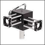
Click to Enlarge
30 mmケージ部品を取り付けたケージシステムアダプタGCM012(/M)
- SM1ネジ付き入力および出力ポート
- 遮光用途向けにガスケットが付属
- 取付け用ネジはすべて付属
ケージシステムアダプタGCM012/Mは、2軸ガルバノシステムGVSx12を30 mmケージシステムに取り付ける際にお使いいただけます。このアダプタには、SM1ネジ付きの入力および出力ポートが付いています。遮光用途に向けたガスケットが1つ付属しており、取付け用のネジも全て付属しています。
注: 入力および出力は異なる面になり、14.7 mm補正されています。ケージシステムもこれに従って適応させる必要があります。

- Fシータ(Θ)レンズやテレセントリック走査レンズLSM05と大径ビーム用ガルバノミラーペア(上記掲載)を取付けるためのブラケット
- 取り外し可能な光入力プレートは30 mmケージシステムならびにSM1ネジシリーズ製品に対応
- 走査レンズを取付けるためにはネジアダプタが別途必要です(下記参照)。
- ミリ規格、インチ規格両方のブレッドボードならびに光学テーブルに取付け可能
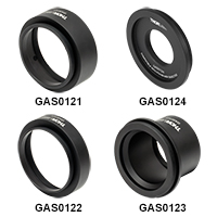
取付けブラケットGAS012によりFシータ(Θ)走査レンズFTH100-1064、FTH160-1064、FTH254-1064、FTH160-1064-M39や、テレセントリック走査レンズLSM05とガルバノメーターミラーペア(上記掲載)を一緒に組み込むことができます。 できあがったアセンブリは、光学テーブルやブレッドボード上の光学システムに組み込むことも可能です。 取付けブラケットGAS012を使用して走査レンズを取り付けるためには別途ネジアダプタのご購入が必要です(下記掲載)。このブラケットによりレンズを2枚目のガルバノミラーに対して適した距離に置くことができます。各走査レンズに取付け可能なアダプタについては下の表をご覧ください。
光入力ポートはSM1ネジ加工付きのプレートでØ25 mm~Ø25.4 mm(Ø1インチ)レンズチューブを取付け可能です。また4個のØ6 mmケージロッド用のネジ穴が付いていて30 mmケージシステムに組み込むことができます。 取付けブラケットGAS012の底部にある取付け面には、12.6 mm間隔の8個のM4貫通穴、および25.2 mm間隔の9個のM6貫通穴があるので、ミリ規格およびインチ規格両方のブレッドボードや光学テーブルに取付け可能となっております。 取付け時、ガルバノミラーペアGVS012/Mは直接底面に載せない構成のため、すべての貫通穴を光学テーブルまたはブレッドボードへの取付けに使用することができます。

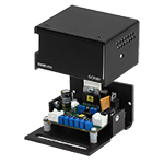
Click to Enlarge
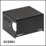
GCE001は、ガルバノシステム用のサーボドライバーボードのカバーとして使えます。
GCE001はサーボドライバーボード用のエンクロージャとしてお使いいただけます。付属のM3ネジと六角レンチを使用して、ボルトで簡単にサーボドライバーブラケットに取り付けられます。
注意: この製品は初期のサーボドライバーボードには使用できません。 詳細につきましては、当社までお問い合わせください。
 Products Home




 ズーム
ズーム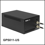

 2軸ガルバノスキャナ:ビーム径<10 mm