超短パルスレーザー用低群遅延分散(GDD)ミラー、700 nm~930 nm
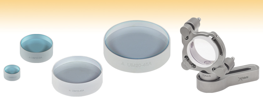
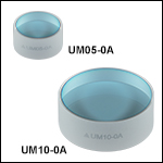
UM10-0A
(Ø1", 0° AOI)
UM20-45A
(Ø2", 45° AOI)
UM05-0A
(Ø1/2", 0° AOI)
Application Idea
UM15-45A Ø1.5" Mirror
in a POLARIS-K15S4 Mount
UM15-45A
(Ø1.5", 45° AOI)
- Ideal for Ti:Sapphire Lasers
- High Reflectance Over 720 - 900 nm (0° AOI) or 700 - 930 nm (45° AOI)
- Group Delay Dispersion: |GDD| < 30 fs2

Please Wait
特長
- 低群遅延分散:: |GDD| < 30 fs2
- 250 fsより短いパルスに適した製品
- 99%以上の反射率
- 入射角(AOI)0°または45°用に設計
- ご提供サイズ
- 入射角0°: Ø12.7 mm(Ø1/2インチ)、Ø25.4 mm(Ø1インチ)
- 入射角45°: Ø12.7 mm(Ø1/2インチ)、Ø25.4 mm(Ø1インチ)、Ø38.1 mm(Ø1.5インチ)、Ø50.8 mm(Ø2インチ)
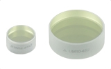
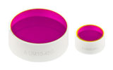
低群遅延分散(低GDD)ミラーは、反射率>99%、および|GDD|< 30 fs2という性能を両立しています。これらのミラーは、パルスの広がりが問題となるようなTi:サファイアフェムト秒レーザや、2光子顕微鏡などのイメージング用途に適しています。型番末尾が-0Aの製品は、入射角0°、波長域720 nm~900 nm用、型番末尾が-45Aの製品は、入射角45°、波長域700 nm~930 nm用に設計されています。誘電体コーティングはイオンビームスパッタリング(IBS)技術で蒸着されています。この技術は制御性に優れ、耐久性の高い誘電体薄膜コーティングを形成できます。反射率とGDDのデータについては、「グラフ」タブをご覧ください。
入射角0°用の低GDDミラーとしては、Ø12.7 mm(Ø1/2インチ)とØ25.4 mm(Ø1インチ)のサイズをご用意しております。入射角45°用の低GDDミラーとしては、Ø12.7 mm(Ø1/2インチ)、Ø25.4 mm(Ø1インチ)、Ø38.1 mm(Ø1.5インチ)およびØ50.8 mm(Ø2インチ)の4種類のサイズをご用意しております。Ø38.1 mm(Ø1.5インチ)の製品は、Ø50.8 mm(Ø2インチ)ミラーよりも設置面積が小さい一方で、Ø25.4 mm(Ø1インチ)ミラーよりも面積が大きいのでより大きなビーム径の高パワー光に対応でき、増幅機能の付いたTi:サファイアレーザーシステム用に適しています。
各ミラーのエッジには型番とコーティング面を示す矢印が刻印されています。Ø12.7 mm(Ø1/2インチ)、Ø25.4 mm(Ø1インチ)、Ø38.1 mm(Ø1.5インチ)ミラーの裏面は研磨されているため、反射コーティングを通り抜けた僅かな光をパワーモニタリングなどにご利用いただけます。
当社のこの低GDDコーティングは、Ti:サファイアレーザの波長域用としては、他のどのミラーよりも高い反射率を有します。当社の低GDDミラーと、超短パルス用銀ミラー、標準的な保護膜付き銀ミラー、および広帯域誘電体ミラーとの一般的な性能比較は「ミラーの比較」タブでご覧いただけます。
当社ではこちらでご紹介している低GDDミラーのほかにも様々な波長域用の低GDDミラーをご提供しています。超短パルスレーザ用光学素子のラインナップについては「超短パルス用光学素子」タブをご覧ください。
ミラーの位相、群遅延、GDD、3次分散、4次分散などの評価については、当社の分散測定システムChromatis™のページをご覧ください。
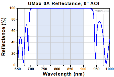
低GDDミラーUMxx-0A、720~900 nm、入射角0°
Click to Enlarge
生データはこちら
このグラフは反射率の波長依存性(理論値)を示しています。これらのミラーには光を垂直に入射するため、反射率の偏光による変化はありません。青い網掛け領域は、反射率>99%の仕様を満たす波長範囲を示しています。なお、この仕様波長範囲以外における反射率は典型値であり、特に変動や傾斜のある領域では製造ロットによって変化する場合があります。
Click to Enlarge
生データはこちら
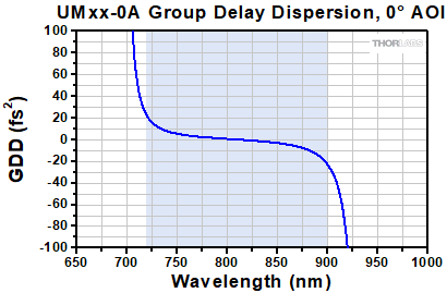
このグラフは、群遅延分散(GDD)の理論計算値を示しています。青い網掛け領域は、GDDの仕様が定められている波長範囲720 nm~900 nmです。これらのミラーには光を垂直に入射するため、GDDの偏光による変化はありません。
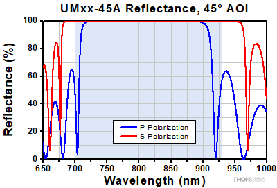
低GDDミラーUMxx-45A、700~930 nm、入射角45°
Click to Enlarge
生データはこちら
このグラフはS偏光およびP偏光両方の反射率の波長依存性(測定値)を示しています。青い網掛け領域は、RS > 99%の仕様を満たす波長範囲を示しています。なお、この仕様波長範囲以外における反射率は典型値であり、特に変動や傾斜のある領域では製造ロットによって変化する場合があります。
Click to Enlarge
生データはこちら
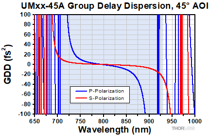
このグラフは、群遅延分散(GDD)の理論計算値を示しています。青い網掛け領域は、GDDの仕様が定められている波長範囲700~930 nmです。S偏光の仕様波長範囲の外部では、GDD値は急激に変動しています。
当社ではTi:サファイアレーザの波長範囲におけるミラーコーティングとして、720~930 nm用低群遅延分散(低GDD)誘電体コーティング(入射角0°)、700~930 nm用低群遅延分散(低GDD)誘電体コーティング(入射角45°)、超短パルス用銀コーティング、標準的な保護膜付き銀コーティング、および広帯域誘電体ミラーコーティング-E02をお勧めしています。ここでは、これらのコーティングの比較をしています。
定性的な比較
当社の低GDD誘電体コーティングと超短パルス用銀コーティングは、特にフェムト秒Ti:サファイアレーザ用に設計されています。低GDD誘電体コーティングは最も高い反射率を有しているため、レーザ共振器に適しています。一方、超短パルス用銀コーティングの反射率はこれよりもわずかに低いものの、波長範囲は若干広くなっています。どちらも|GDD| < 30 fs2を満たしています。
保護膜付き銀コーティングはスペクトル範囲が最も広く、入射角への依存性が最も低くなっています。しかし、典型的なTi:サファイア波長における反射率は、低GDD誘電体コーティング、および超短パルス用銀コーティングよりも若干低くなっており、またGDDの仕様値は示されていません。
広帯域誘電体ミラーコーティング-E02は、誘電体コーティング層内で共振する構造を有します。この構造は群遅延分散にリップルを発生させる原因になり、さらにコーティングのロットによって大きなバラツキが生じる可能性があります。このようなバラツキはCWでの動作には影響を与えませんが、超短パルスレーザをそのようなミラーで反射した場合にはパルスが大きく歪みます。当社の低GDD誘電体コーティングおよび超短パルス用銀ミラーの誘電体コーティングは、ミラー層の中で共振しないよう設計されているため、分散と反射率は設計波長全域に渡って緩やかに変化します。
仕様の比較
Table 3.1では各コーティングの反射率、スペクトル範囲、群遅延分散についてまとめています。
| Table 3.1 Specifications | |||||||
|---|---|---|---|---|---|---|---|
| Mirror Coating | Item # Suffix | Angle of Incidence | Spectral Range | Reflectance | Group Delay Dispersion | ||
| Low-GDD Dielectric Coatings | -0A | 0° | 720 - 900 nm | R > 99% | |GDD| < 30 fs2 | ||
| -45A | 45° | S-Pol: 700 - 930 nm P-Pol: 730 - 870 nm | Rs > 99% Rp > 99% | S-Pol: |GDD| < 30 fs2 P-Pol: |GDD| < 30 fs2 | |||
| Ultrafast-Enhanced Silver Coating | -AG | 45° | 750 - 1000 nm | Rs > 99.0% Rp > 98.5% | S-Pol: |GDD| < 20 fs2 P-Pol: |GDD| < 30 fs2 | ||
| Protected Silver Coatings | -P01 | 0° - 45° | 450 nm - 20 µm | Ravg > 97.5% for 450 nm - 2 µm Ravg > 96% for 2 - 20 µm | Not Specifieda,b | - | |
| -P02 | 0° - 45° | Ravg > 97% for 450 nm - 2 µm Ravg > 95% for 2 - 20 µm | Not Specifieda,b | - | |||
| Broadband Dielectric Coating | -E02 | 0° - 45° | 400 - 750 nm | Ravg > 99% | Not Specifiedb | - | |
| Posted Comments: | |
Shaogang Yu
(posted 2020-08-25 11:24:26.863) 你好,我向贵司购买的UM10-45镜子,发现有很大一部分光透过,请问这是什么原因了?我是用的飞秒光脉宽是10fs,功率为600mW。 YLohia
(posted 2020-08-25 10:18:11.0) Hello, thank you for contacting Thorlabs. An applications engineer from our team in China will contact you directly. Brennan Peterson
(posted 2019-09-05 13:03:53.227) Hello,
Can you provide the coating type (IBS or ebeam) to understand the damage behavior. YLohia
(posted 2019-09-05 02:35:59.0) Hello, thank you for contacting Thorlabs. Most of our low dispersion mirror coatings, including the -45A, are IBS. Volker Sonnenschein
(posted 2019-06-13 07:55:32.9) How accurate is the Reflectance curve provided for these mirrors? As i doubt it is truly up to 99.996% as indicated in the excel sheet, i wonder how much absorption+scatter should be subtracted from the reflectivity value. asundararaj
(posted 2019-06-22 11:16:01.0) Thank you for contacting Thorlabs. The reflectance curves on the website are theoretical and don't account for absorption or scatter. We only specify 99% reflectance because we can confidently say that the coating has significantly less than 1% loss to scatter and absorption. slm9
(posted 2014-08-22 11:23:26.39) Dear Thorlabs-Team
Do you have some specs for this coating if this mirror will be used under AOI 0°? I would like to know the spectral shift and the low GDD behavior @AOI 0°.
Thanks and with best regards
Markus jlow
(posted 2014-09-18 02:07:45.0) Response from Bweh at Thorlabs USA: We have theoretical plots for the reflectivity and GDD when used at 0 deg in comparison to 45 deg. Our European office will followup with you by email regarding this. oliver.sandig
(posted 2014-06-08 11:48:35.417) Hallo,
ich suche ein Ultrafast-Spiegel der reflektierend für 800nm und transparent für 400nm ist, oder umgedreht.
Können Sie mir dafür ein Spiegel empfehlen?
Vielen Dank,
Oliver Sandig besembeson
(posted 2014-06-12 05:05:59.0) A Response from Bweh at Thorlabs Newton-USA: Thanks for contacting Thorlabs. We don't carry such an ultrafast mirror at the moment that will reflect 400nm and transmit 800nm or vice versa. We do have dual band 400nm and 800nm high reflectivity ultrafast mirrors: (http://www.thorlabs.com/newgrouppage9.cfm?objectgroup_id=3179). I am curious about your application so I will contact you through our Germany office to find out more, and to determine if another stock item may work or if we have to look into a special coating for your application. theresa.bruemmer
(posted 2014-02-10 10:52:39.893) Do You have estimates on the damage threshold of these mirrors? Thanks, Theresa besembeson
(posted 2014-02-12 03:59:33.0) Response from Bweh E. at Thorlabs: Hi Theresa, These mirrors are ideal for Ti:Sapphire femtosecond pulsed lasers. The coating on this should withstand 1.5W of 800nm ultra-fast pulse with durations as short as 50fs, and 300mW of 400nm ultra-fast pulses with durations as short as 50fs. These numbers are based on a minimum laser beam diameter of about 1.2mm.
Note that Pulsed lasers typically induce a different type of damage to the optic than CW lasers. Pulsed lasers often do not heat the optic enough to damage it; instead, pulsed lasers produce strong electric fields capable of inducing dielectric breakdown in the material (avalanche ionization). I will send you separate email requesting your laser characteristics to determine if this optic is suitable for your laser or not. tcohen
(posted 2013-01-15 12:09:00.0) Response from Tim at Thorlabs to Neil: Thank you for your feedback. I will send you measured data to supplement the calculated data provided on the “Graphs” tab. We will continue to update our presentation with more data. steve.u.smith
(posted 2013-01-14 14:15:34.98) Do you have the measured GDD curve to share to help me make a purchasing decision?
Thanks
Neil |
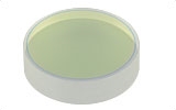
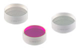
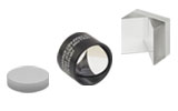
フェムト秒パルスレーザ用ならびにピコ秒レーザ用光学素子を幅広くご用意しています。詳細は下表をご参照ください。
| Dielectric Mirror | High-Power Mirrors for Picosecond Lasers | Metallic Mirrors | Low-GDD Pump-Through Mirrors | ||
|---|---|---|---|---|---|
 |  |  | 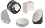 | 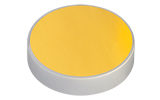 | 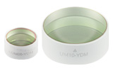 |
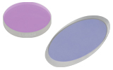
| Dual-Band Dielectric Mirror, 400 nm and 800 nm | Ytterbium Laser Line Mirrors, 250 nm - 1080 nm | Ultrafast-Enhanced Silver Mirrors, 750 - 1000 nm | Protected Silver Mirrors, 450 nm - 20 µm | Unprotected Gold Mirrors, 800 nm - 20 µm | Pump-Through Mirrors, 1030 - 1080 nm and 940 - 980 nm |
| Deterministic GDD Beamsplitters | Low-GDD Harmonic Beamsplitters | Low-GDD Polarizing Beamsplitters | β-BBO Crystals | Dispersion-Compensating Optics | |
|---|---|---|---|---|---|
 |  |  |  | 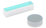 | 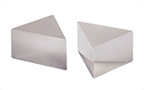 |
| Beamsplitters & Windows, 600 - 1500 nm or 1000 - 2000 nm | Harmonic Beamsplitters, 400 nm and 800 nm or 500 nm and 1000 nm | High-Power, Broadband, High Extinction Ratio Polarizers, 700 - 1300 nm | β-BBO Crystals for Second Harmonic Generation | Dispersion-Compensating Mirrors, 650 - 1050 nm | Dispersion-Compensating Prisms, 700 - 900 nm |

| Item # | UM05-0A | UM10-0A |
|---|---|---|
| Design Wavelength Range | 720 - 900 nm | |
| Diameter | 1/2" (12.7 mm) | 1" (25.4 mm) |
| Diameter Tolerance | +0.00 / -0.10 mm | |
| Clear Aperture | >80% of Diameter | |
| Thickness | 6.4 mm (0.25") | 9.5 mm (0.37") |
| Thickness Tolerance | ±0.20 mm | |
| Reflectance | R > 99% | |
| Angle of Incidence | 0° | |
| Group Delay Dispersion | |GDD| < 30 fs² | |
| Laser Induced Damage Thresholda | 0.40 J/cm2 (800 nm, 52 fs FWHM, S-Pol, 1000 Pulses) | |
| Substrate | Fused Silica | |
| Front Surface Flatnessb | λ/3 | λ/10 |
| Front Surface Quality | 15-5 Scratch-Dig | |
| Parallelism | ≤3 arcmin | |
| Back Surface | Polished | |

| Item # | UM05-45A | UM10-45A | UM15-45A | UM20-45A |
|---|---|---|---|---|
| Design Wavelength Range | 700 - 930 nm | |||
| Diameter | 1/2" (12.7 mm) | 1" (25.4 mm) | 1.5" (38.1 mm) | 2" (50.8 mm) |
| Diameter Tolerance | +0.00 / -0.10 mm | |||
| Clear Aperture | > 80% of Diameter | |||
| Thickness | 6.4 mm (0.25") | 9.5 mm (0.37") | 12.0 mm (0.47") | 12.0 mm (0.47") |
| Thickness Tolerance | ±0.20 mm | ±0.10 mm | ||
| Reflectance | Rs > 99% (700 - 930 nm) Rp > 99% (730 - 870 nm) | |||
| Angle of Incidence | 45° | |||
| Group Delay Dispersion | |GDDs| < 30 fs² (700 - 930 nm) |GDDp| < 30 fs² (730 - 870 nm) | |||
| Laser Induced Damage Thresholda | 0.40 J/cm2 (800 nm, 52 fs FWHM, S-Pol, 1000 Pulses) | |||
| Substrate | Fused Silica | |||
| Front Surface Flatnessb | λ/4 | λ/6 | λ/4 | λ/2 |
| Front Surface Quality | 15-5 Scratch-Dig | 20-10 Scratch-Dig | ||
| Parallelism | ≤3 arcmin | ≤5 arcmin | ||
| Back Surface | Polished | Fine Ground | ||
 Products Home



 ズーム
ズーム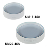
 低GDDミラー、