 Products Home
LED、メタルコアPCB基板実装済み
- UV, Visible, IR, and Mid-IR Models Available
- LED Mounted on Metal-Core Printed Circuit Board
- Ideal for OEM Applications
M340D4
340 nm LED,
≥45.5 mW Power Output
M1300D3
1300 nm LED,
≥122.8 mW Power Output
M565D2
565 nm LED,
≥880 mW Power Output


Please Wait
特長
- 公称波長範囲:265~5200 nm
- 白色、デュアルピーク、広帯域のLEDもご用意
- 最小出力範囲:1.1 mW~2000 mW
- 優れた熱設計:メタルコアPCB回路基板上に取り付けられたLED
- 長寿命(下表参照)
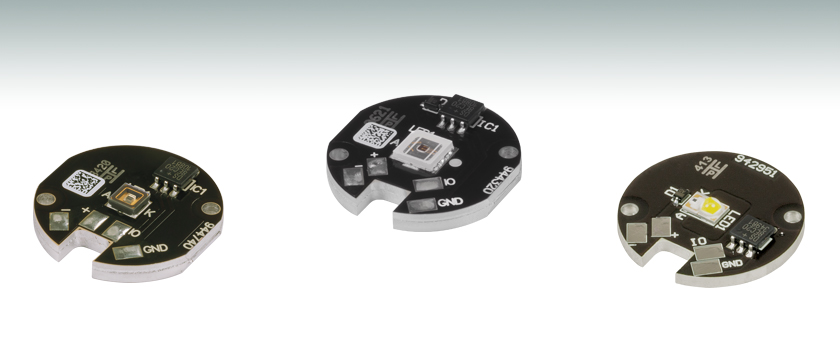
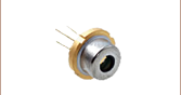
メタルコアのプリント基板回路(MCPCB)に取り付けられたLEDは、小型のパッケージながら高い出力が得られます。各LEDパッケージは、MCPCB上にはんだ付けされた単一のLEDで構成されています。量産や組み込み(OEM用途)、または実験用のLEDですので、一般家庭での照明用としてはお使いいただけません。
当社のMCPCBには熱伝導性の高い材料を使用しています。MCPCBの構造も熱を適切に処理できるように設計されています。しかし、LEDの正常な動作と長期の寿命を実現するには、LEDをサーマルペーストを用いて適切なヒートシンクに取付けることが必要です。MCPCBの表面にはLEDをヒートシンクに取付けるためのØ2 mmの貫通穴があり、M2ネジを用いて取付けることができます(ネジは製品に付属しません)。
各LEDのスペクトルと詳しい仕様は、下記の青いInfoアイコン(![]() )をクリックするとご覧いただけます。LED同士を比較していただけるように、複数のウィンドウを同時に開くことができます。
)をクリックするとご覧いただけます。LED同士を比較していただけるように、複数のウィンドウを同時に開くことができます。
当社では、主要メーカの顕微鏡にも取付け可能な、ヒートシンクの付いたマウント付きLEDや、コリメータが付いたマウント付きLEDもご用意しております。ファイバを使用するアプリケーションには、ファイバ出力型LEDもございます。お客様の用途に適したLEDの選択やマウントに関するご質問がありましたら、当社にご相談ください。
最適化された熱設計
これらのLEDにサーマルペーストや熱伝導両面テープを用いて適切にヒートシンクを取り付ければ、その優れた熱設計によりLEDの温度上昇に伴う光出力の低下は問題になりません。
白色、デュアルピーク、および広帯域LED
当社のウォームホワイト、ニュートラルホワイト、コールドホワイトの各LEDは数百nmにわたる広いスペクトルを有しています。これら3種類のLEDの色の違いは相関色温度(色が最も近い黒体放射の温度)で表すことができます。一般に、ウォームホワイトLEDはタングステン光源に似たスペクトルを有しますが、コールドホワイトLEDでは青色のスペクトル成分が多くなります。ニュートラルホワイトLEDは、可視域においてウォームホワイトやコールドホワイトよりも平坦な照明スペクトルを有します。コールドホワイトLEDはウォームホワイトLEDに比べてほとんどの波長で強度が高いため、蛍光顕微鏡やホワイトバランス調整のできるカメラなどに適しています。ニュートラルホワイトLEDは植物育成などに適しています。
赤色と青色の両方のスペクトル成分を有する照明を必要とする植物工場等の用途には、MPRP1D2をご用意しています。この紫色LEDは、光合成を促進するために、455 nmと640 nmの2波長にピークがあります(光合成色素の吸収ピークとLEDのスペクトルとの比較についてはこちらのグラフをご覧ください)。また植物が均一に成長できるよう、発光スペクトルの赤色と青色の強度比はLEDの寿命を通じて維持されるように設計されています。
広帯域LED MBB1D1では、広い波長域にわたり比較的平坦なスペクトルが得られます。その半値全幅(FWHM)の波長範囲は500 nm~780 nm、10 dB帯域幅の波長範囲は470 nm~850 nmです。広帯域LED MBB2D1のスペクトルは770 nm、860 nm、940 nmの各近傍にピークがあります。
はんだ付け
これらのLEDは熱抵抗の小さいメタルコアにはんだ付けされています。このメタルコアは優れた熱伝導性を有するため、パッケージにヒートシンクを接続した状態ではんだ付けを行おうとすると、メタルパッドがはんだ付けに必要な温度に達しない場合があります。ワイヤを適切にパッドにはんだ付けするためには、まず、メタルコアがヒートシンクや金属の表面に接触していないことをご確認ください。はんだ付けする際は、MCPCBを小型の万力などを使用して固定し、ゲージがAWG24(0.25 mm2)のワイヤを使用することをお勧めします。
ワイヤをMCPCBにはんだ付けするときは、まずはんだ付けの温度を約350 °Cに設定し、はんだごてのこて先をパッドの1つに30秒ほど当てます。はんだごてによりが熱くなりますので、はんだ付け作業が終わった後も、LEDのパッケージ全体の温度が下がるまで触れないようご注意ください。パッドの温度の確認は、錫はんだをパッドに当て行います。適正な温度であれば、はんだは溶解してパッド全体に均一に広がります。もう一方のパッドも錫はんだでコーティングします。次に、パッドにワイヤをはんだ付けします。ピンセットやプライヤを用いてMCPCBを万力から外し、ヒートシンクまたは金属の表面に置きます。しばらく待って、メタルコアPCBの温度が下がったら、ご使用いただけます。
「LEDドライバ」タブの表内にあるLEDとドライバを接続する場合は、別売りのLED接続ケーブルCAB-LEDD1(下記参照)をお使いいただくと便利です。
ドライバとピン配置
当社ではこれらの一部またはすべてのLEDに対応するドライバとして、LEDD1B、UPLED、DC40、DC2200、DC4100、DC4104の6種類をご用意しています(ドライバDC4100、DC4104にはDC4100-HUBが必要です)。対応するドライバとドライバの仕様については「LEDドライバ」タブをご覧ください。ドライバUPLED、DC40、DC2200、DC4100、DC4104は接続されたLEDのEEPROMから電流のリミット値を読み取り、最大電流値を自動的に設定してLEDを保護することができます。
PCBをドライバに接続する際は、「+」と標識されたはんだ付けパッドがアノード側(+V)で、「-」と標識されたはんだ付けパッドがカソード側であることにご注意ください。これらのLEDは、EEPROM IOとEEPROM GNDに接続しなくても動作しますが、ドライバが電流リミット値を読み取るためには接続する必要があります。はんだ付けパッドの位置は製品によって異なりますが、ラベルは同じです。
コリメーション
これらのLEDは視野角が大きいため、多くの用途ではビームをコリメートすることが有効です。LED光のコリメート方法の詳細は「コリメーション」タブをご覧ください。
相対出力
LEDの実際の出力スペクトルや合計出力値は、製造バラつきや温度や電流などの動作パラメータの違いによって変動します。 適切なLEDをお選びいただくために出力の典型値と最低値を明記しました。 メタルコアPCB LEDは、最大電流において少なくても記載されている最少パワーを出力します。 異なる公称波長において比較するため、下記のプロットではスペクトルは各LEDの最少出力値を表示しています。 このデータは代表値です。すべてのマウント済みLEDのスペクトルデータをまとめたエクセルファイル(規格化データおよびスケーリングデータ)はグラフ下のリンクからダウンロードいただけます。


LEDの寿命および長期的なパワー安定性
LEDの特性の1つとして、時間の経過と共にパワーが自然に低下することが挙げられます。ほとんどの場合、パワーは緩やかに低下しますが、急速な低下や完全な停止、あるいは故障が突然起こることもあります。 LEDの寿命は、LEDの種類ごとに規定されたある割合のLEDが、あるパワーレベル以下に低下するまでの時間で定義されます。寿命測定のパラメー タはBXX/LYYで表され、ここでXXはその種類のLEDで寿命が過ぎた後の出力パワーが規定値のYY%以下になるLEDの割合を示します。当社では、LEDの寿命をB50/L50で 表しますが、これはその型番のLEDのうち50%のLEDの光パワーが規定の寿命がきた時に初期値の50%以下に低下するという意味です。例えば、定格出力パワー150 mWのLED100個のうち、50個の出力パワーが規定の寿命を過ぎたときに75 mW以下に低下するということです。
最適化された温度管理
安定的な出力と寿命を最大限に伸ばすため、このメタルコアのプリント基板回路は熱伝導性ペーストを使用し適切にヒートシンクに取り付ける必要があります。これにより、LED接合部の温度上昇に起因する光出力パワーの低下が最小限に抑えられます(右のグラフをご参照ください)。
駆動するLEDから最大の光パワーを出力させるには、LEDの最大電圧および最大電流と同等あるいはそれ以上の電圧と電流を出力できるドライバが必要です。
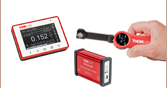
| Compatible Drivers | LEDD1B | UPLEDa | DC40a | DC2200a | DC4100a,b | DC4104a,b |
|---|---|---|---|---|---|---|
| Click Photos to Enlarge | 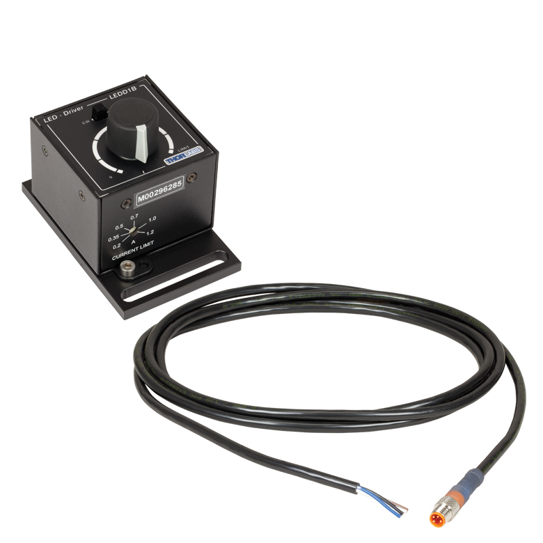 |  |  |  |  |  |
| LED Driver Current Output (Max)c | 1.2 A | 1.2 A | 4.0 Ad | LED1 Terminal: 10.0 A LED2 Terminal: 2.0 Ae | 1.0 A per Channel | 1.0 A per Channel |
| LED Driver Forward Voltage (Max)f | 12 V | 8 V | 14.0 Vd | 50 V | 5 V | 5 V |
| Modulation Frequency Using External Input (Max) | 5 kHzg | - | 5 kHzg | 250 kHzg,h | 100 kHzg (Simultaneous Across all Channels) | 100 kHzg (Independently Controlled Channels) |
| External Control Interface(s) | Analog (BNC) | USB 2.0 | USB 2.0, TTL, and Analog (BNC) | USB 2.0 and Analog (BNC) | USB 2.0 and Analog (BNC) | USB 2.0 and Analog (8-Pin) |
| Main Driver Features | Very Compact Footprint 60 mm x 73 mm x 104 mm (W x H x D) | USB-Controlled | Driver Current Up to 4.0 A, Manual and USB-Controlled | Touchscreen Interface with Internal and External Options for Pulsed and Modulated LED Operation | 4 Channelsb | 4 Channelsb |
| EEPROM Compatible: Reads Out LED Data for LED Settings | - | |||||
| LCD Display | - | - | - |
Video Insight(How-to動画): LEDからの出力光をコリメートする方法
LEDやその他の寸法の大きなインコヒーレント光源からの光をコリメートするのは、意外にも難しい作業になる場合があります。エミッタのサイズ、コリメート用レンズの焦点距離と開口数(NA)など、それらのすべてがコリメートされたビームの特性に影響します。また、レンズが適切な位置にあることを見極めるのも難しい場合があります。この動画では、NAと焦点距離の異なる2つのレンズを使用して、いくつかのコリメート方法をデモンストレーションしています。そのほか、コリメートレンズによって生じるエミッタの像やその他の一般的なビームの特徴についてもご紹介します。
| Item # | Information File | Available Ray Files | File Size | Click to Download |
|---|---|---|---|---|
| M385D1 | M385_Info.pdf | 1 Million Rays and 5 Million Rays | 147 MB | |
| M850D2a | SFH4715S_100413_info.pdf | 100,000 Rays, 500,000 Rays, and 5 Million Rays | 139 MB | |
| M940D2a | SFH_4725S_110413_info.pdf | 100,000 Rays, 500,000 Rays, and 5 Million Rays | 140 MB |
高出力光源に組み込まれているLED単体のZemax用光線データをご用意しております。右のテーブルの右端の赤いアイコン( )をクリックすると、ZIP形式のフォルダをダウンロードすることができます。ZIPフォルダには、資料ファイルとZemaxで使用するための光線データファイルが含まれています。
- 資料ファイル:このドキュメントには、ZIPフォルダ内のデータファイルの種類とご利用にあたっての基本情報が入っています。また、それぞれのドキュメントの種類と対応するファイル名のリストも含まれています。
- 光線ファイル:Zemaxで使用するための光線データが含まれているバイナリファイルです。
右の表で「a」の上付き文字が付いているLEDについては、次のような情報もZIPフォルダ内に入っています。
- スペクトルデータ:このSPCファイルもZemaxでの使用を想定したデータです。
- CADファイル :LED単体の形状を示すファイルです。筐体を含むマウント済み高出力LEDの寸法については、当社がご提供している補足図面をご覧ください。
- Zemaxファイルのサンプル :サンプルファイルには、Zemaxで使用する際の、光線ファイルとLED単体のCADモデルに関する推奨される設定と配置が含まれています。
右の表は各LEDに対応する光線ファイルおよび参考資料の一覧です。
| Posted Comments: | |
prathmesh ghag
(posted 2023-10-19 15:09:13.14) Sir,
Are these LED vacuum compatible.
Kindly tell for model M810D2
Thanks,
Prathmesh Ghag dpossin
(posted 2023-10-20 07:12:57.0) Dear Prathmesh,
Thank you for your feedback. Unfortunately none of our metal core PCB mounted LEDs are vacuum compatible. Su Bemo Heo
(posted 2023-06-22 17:18:01.56) Hi I just saw Specifications about [M167D4].
It' seems Nominal wavelength is 617nm but Peak Wavelength is 620 ~ 630nm so what's different between Nominal and Peak
Also what is Typical Wavelength(625nm) ? why is different Nominal Wavelength (617nm)
Thanks hkarpenko
(posted 2023-06-23 06:39:48.0) Dear customer,
thank you for your feedback. The nominal wavelength is the nominal wavelength at which the LED appears brightest to the human eye. The central wavelength spec is the measured wavelength from a spectrometer. This only makes a difference for some visible wavelengths. Since the emission wavelength and output power can vary due to the production process, we state a minimum, typical and maximum value, in between the peak wavelength will be located. This is based on our measurements and experience. wang xiaozhuo
(posted 2023-06-06 20:34:52.723) Hi thorlabs, I wonder do you have real rayfile of M780D2 LED for Lighttools? hchow
(posted 2023-06-07 10:20:14.0) Dear Mr. Wang, thank you for your feedback. I will reach out to you directly to address your issue. MARIO MARTINELLI
(posted 2023-02-24 13:28:12.4) What is the appropriate driver for M530D3? Thanks hchow
(posted 2023-02-24 09:20:03.0) Dear Mr. Martinelli, thank you for your feedback. Our LEDs on Metal-Core PCBs can be driven by our LEDD1B, DC2200, DC4100, and DC4104 (the latter two require the DC4100-Hub). You can additionally purchase the CAB-LEDD1, LED connect cable to connect the LED to the LED driver. ke chen
(posted 2022-07-14 04:22:02.07) 我想用一段二进制伪随机编码对光源的亮灭进行调制,从而间歇性的使石墨烯产生光电效应而产生离子,请问这个产品能完成这个任务吗 mdiekmann
(posted 2022-07-18 06:05:04.0) Thank you for contacting us. A member of our Chinese-speaking tech support team will reach out to you directly to assist. fred couweleers
(posted 2022-07-01 14:23:34.443) can you tell me whether the conductive structures that are visible on the surface of the LED are always oriented the same way with respect to the PCB (within a certain tolerance)? Mehrdad Hosseini
(posted 2022-06-13 08:51:04.24) Hello,
As you mentioned in the datasheet, the maximum current for M595D3 is 1500 mA, but I can't apply more than 800 mA with 3.2V. Can I increase the voltage to reach maximum current (and highest intensity)? If so, to what extent?
Best Regards,
Mehrdad fmortaheb
(posted 2022-06-14 03:14:41.0) Dear Mehrdad, Thank you very much for your inquiry. we have contacted you directly to provide further assistance and troubleshooting. Faye Clever
(posted 2021-12-01 08:44:07.61) I have been using these MINTD3 LEDs for an optogenetics project I am working on with model organism C. elegans for a little over a year. The LEDs have been exactly what I needed. My only concern is the ease of soldering these LEDs. I have had a number of people work on the soldering with some frustration. Because it has been multiple people, all of whom have respectable soldering experience, I am inclined to believe that there may be some issue with the LEDs themselves. I have so far purchased 9 MINTD3s and the soldering has actually detached from the LEDs during use - when I first set up the LEDs, everything works fine, but when I come back hours later the soldering will be detached. I could be wrong, but if this is in fact an issue with the LEDs' soldering then I figured you would want to know. dpossin
(posted 2021-12-06 05:04:52.0) Dear Faye,
Thank you for your feedback. I reach out to you directly in order to discuss this. Hyeonsoo OH
(posted 2021-10-01 17:05:30.257) Hello.
I`m a assistant manager in Company called U2medtek which is medical engineering in korea.
We bought it. and we are very satisfied about it.
Do you have Certificate of EN-62471 for it?
If you have please send PDF file on e-mail.
For making medical equipment, We need that certs.
If you want to know about us, you can send a e-mail to this address.
and this is our homepage address.
Homepage: www.U2medtek.com
thank you
Best Regards soswald
(posted 2021-10-04 05:52:55.0) Dear Hyeonsoo OH,
thank you for your feedback. I am glad to hear you are satisfied with the M780D2.
We have rated this LED as RG0 according to EN-62471, as stated in the specification sheet: https://www.thorlabs.de/drawings/86f2f178eb4c904c-E3DE4C1C-0EB5-F577-6725F18F3430EA4E/M780D2-SpecSheet.pdf
I have reached out to you directly in order to provide further assistance if needed. Hajun Song
(posted 2020-11-09 01:45:59.967) I want to use the LD as a flash for the high speed flash. So, the LD should be modulated as fast as possible. Could you give me a information about the LD's bandwidth or rising time? dpossin
(posted 2020-11-09 10:13:11.0) Dear Hajun,
Thank you for your feedback. Unfortunately we do not have information on the rise time of our metalcore PCB LEDs due to the fact that we are bandwidth limited by our drivers. However a good assumption is a rise time of at least 100ns which corresponds to an 3dB bandwidth of 3.5 MHz. Ulrich Leischner
(posted 2020-07-09 05:32:47.76) Hallo
gäbe es diese LED auch für 1000mA Stromstärke?
wir benützen den Wellenlängenbereich ab 1070nm für quasi-IR Imaging, also den Grenzbereich der grad noch mit Silizium-Chips machbar ist. Mit einer IR-Quelle und einem 1070nm Langpassfilter hat man ganz gute ergebnisse. Unsere Stromversorgungen sind standardisiert auf 1000mA. Wenn es da LEDs gäbe im Bereich 1050nm-1200nm mit 1000mA wären die für uns gut zu gebrauchen. Gäbe es da inzwischen LEDs in diesem Bereich?
Grüße
Ulrich Leischner MKiess
(posted 2020-07-10 09:36:13.0) Vielen Dank für Ihre Anfrage. Eine IR-LED, mit einer Wellenlänge zwischen 1050nm und 1200nm, auf einem Metallkern PCB, welche bei 1000mA betrieben werden kann, haben wir leider nicht als standard Produkt in unserem Sotrtiment. Eine Übersicht aller LEDs können Sie unter folgendem Link finden:
https://www.thorlabs.de/newgrouppage9.cfm?objectgroup_ID=6071&tabname= LED Selection Guide
Ich habe Sie direkt kontaktiert um die genauen Anforderungen mit Ihnen zu diskutieren. alekkom
(posted 2017-12-15 11:09:23.127) Can I use laser diode driver LD3000R as LED driver for M780D3 diode? swick
(posted 2017-12-20 03:52:04.0) This is a response from Sebastian at Thorlabs. Thank you for the inquiry.
In general it should work to drive LEDs with constant current drivers so LD3000R (2.5 A , 12 V) should be compatible to M780D3 (800 mA, 7.8 V). ludoangot
(posted 2017-11-16 22:57:56.71) Which of your white LED has the highest Color Rendition Index (CRI)? mvonsivers
(posted 2017-11-21 04:47:52.0) This is a response from Moritz at Thorlabs. Thank you for you inquiry.
Unfortunately, we cannot specify CRI values for our LEDs.
I will contact you directly for further information. ludoangot
(posted 2016-05-24 23:39:01.57) Do you offer sm1 sized blank mounting plates for these LED? I have in mind 2 configurations: a 1" pre-drilled plate to insert in sm1 tubes or the same but with SM1 external thread. shallwig
(posted 2016-05-25 02:29:13.0) This is a response from Stefan at Thorlabs. Thank you very much for your inquiry. These LEDs on Metal-Core PCB must still be mounted onto an appropriate heat sink using thermal paste to ensure proper operation and to maximize operating lifetime. We do not offer these heat sinks separately. Our mounted LEDs with heatsink http://www.thorlabs.com/newgrouppage9.cfm?objectgroup_ID=2692 feature an internal SM1 Threading for attaching collimation adapters or 1’’ lens tubes.
I will contact you directly to discuss your application in more detail. kwestla
(posted 2015-01-29 13:03:14.38) What is the control voltage needed to turn the device on via the EEPROM IO, is it TTL, CMOS etc? shallwig
(posted 2015-01-30 05:24:28.0) This is a response from Stefan at Thorlabs. Thank you very much for your inquiry. The EPROM cannot be used to turn the LED on. This chip only has saved information about the maximum driving current for this specific LED. It gets connected with an EPROM compatible driver like the DC2100 via the IO and GND Pad but the LED and EPROM have two different circuits. The driver reads out the EPROM information and sets the current limit accordingly.
The M385D1 needs to be supplied via Cathode and Anode Pad with a constant current of 700 mA, the current must not exceed the max current of 700 mA. The current source must be able to deliver this current at a “Forward Voltage” of 4.3 V.
I will contact you directly to discuss your application in detail. jamesfreal
(posted 2013-08-27 11:58:01.013) The Excel data file for the M365D1 is not correct on your web site. It looks like it contains the spectral data for the M505D2. Could you send me the correct file?
Thanks
James Freal sharrell
(posted 2013-08-27 12:35:00.0) Response from Sean at Thorlabs: Thank you for contacting us. We’ve updated the file linked on our website with the correct data. |
こちらのページでは当社が販売するすべてのLEDをご覧いただけます。More [+]をクリックすると、下の各LED製品の波長をご覧いただけます。
| Light Emitting Diode (LED) Selection Guide | ||||||
|---|---|---|---|---|---|---|
| Click Photo to Enlarge (Representative; Not to Scale) |  |  |  |  |  |  |
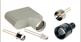
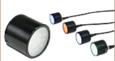
| Type | Unmounted LEDs | Pigtailed LEDs | LEDs in SMT Packages | LED Arrays | LED Ring Light | Cage-Compatible Diffuse Backlight LED |
| Light Emitting Diode (LED) Selection Guide | ||||||
|---|---|---|---|---|---|---|
| Click Photo to Enlarge (Representative; Not to Scale) |  |  |  |  |  |  |
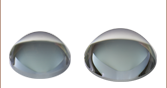
| Type | PCB- Mounted LEDs | Heatsink- Mounted LEDs | Collimated LEDs for Microscopyb | Fiber- Coupled LEDsc | High-Power LEDs for Microscopy | Multi-Wavelength LED Source Optionsd |
当社の深紫外LEDは、動作中高強度のUV光を放射します。UV光は直接見ないようにしてください。目の損傷を防止するため、ご使用の際はUV光用保護メガネを必ずご着用ください。UV光に肌や身体をさらさないようにしてください。
| Item # | Infoa,b | Nominal Wavelength | LED Output Power | Bandwidth (FWHM) | Irradiancec | Maximum Current (CW) | Forward Voltage | Viewing Angle (Full Angle at Half Max) | Emitter Size | MCPCB Thickness | |
|---|---|---|---|---|---|---|---|---|---|---|---|
| Minimum | Typical | ||||||||||
| M265D4 | 265 nm | 38.4 mW | 55.7 mW | 11 nm | 0.5 µW/mm2 | 440 mA | 6.9 V | 120º | 1 mm x 0.75 mm | 1.6 mm | |
| M275D2 | 275 nm | 45 mW | 80 mW | 11 nm | 0.8 µW/mm2 | 700 mA | 7.3 V | 118° | 2 mm x 2 mm | 1.6 mm | |
| M275D3 | 275 nm | 47.3 mW | 68.3 mW | 10 nm | 0.5 µW/mm2 | 300 mA | 12 V | 120° | 2.7 mm x 3.3 mm | 1.6 mm | |
| M280D4 | 280 nm | 78 mW | 114 mW | 10 nm | 1 µW/mm2 | 500 mA | 6.26 V | 114°d | 1 mm x 1 mm | 1.6 mm | |
| M300D3 | 300 nm | 26 mW | 32 mW | 20 nm | 0.3 µW/mm2 | 350 mA | 8.0 V (Max) | 130° | 1 mm x 1 mm | 1.6 mm | |
| M310D1 | 310 nm | 38.5 mW | 56.5 mW | 30 nm | 0.76 µW/mm2 | 600 mA | 5 V | 120°d | 1 mm x 1 mm | 1.6 mm | |
| M325D3 | 325 nm | 25 mW | 35 mW | 12 nm | 0.44 µW/mm2 (Max) | 600 mA | 5.2 V | 120° | 1 mm x 1 mm | 1.6 mm | |
| M340D4 | 340 nm | 45.5 mW | 69.2 mW | 10 nm | 0.6 µW/mm2 | 600 mA | 6.6 V | 120°d | 1 mm x 1 mm | 2.4 mm | |
UV LEDは、動作中高強度のUV光を放射します。UV光は直接見ないようにしてください。目の損傷を防止するため、ご使用の際はUV光用保護メガネを必ずご着用ください。UV光に肌や身体をさらさないようにしてください。
| Item # | Infoa,b | Nominal Wavelength | LED Output Power | Bandwidth (FWHM) | Irradiance (Typical)c | Maximum Current (CW) | Forward Voltage | Viewing Angle (Full Angle at Half Max) | Emitter Size | MCPCB Thickness | |
|---|---|---|---|---|---|---|---|---|---|---|---|
| Minimum | Typical | ||||||||||
| M365D2 | 365 nm | 1150 mWd | 1400 mWd | 9 nm | 17.6 µW/mm2 d | 1700 mA | 4.0 V | 120° | 1.4 mm x 1.4 mm | 2.4 mm | |
| M375D4 | 375 nm | 1270 mW | 1540 mW | 9 nm | 19.2 µW/mm2 | 1400 mA | 3.6 V | 130° | 1 mm x 1 mm | 2.4 mm | |
| M385D2 | 385 nm | 1650 mW | 1830 mW | 12 nm | 23.3 µW/mm2 | 1700 mA | 3.9 V | 120° | 1.4 mm x 1.4 mm | 2.4 mm | |
| M395D3 | 395 nm | 400 mW | 535 mW | 16 nm | 6.7 µW/mm2 | 500 mA | 4.5 V | 126° | 1 mm x 1 mm | 2.4 mm | |
| M395D4 | 395 nm | 1420 mW | 2050 mW | 11 nm | 22.8 µW/mm2 | 1400 mA | 4.0 V | 120° | 2.5 mm x 2.5 mm | 2.4 mm | |
| M405D2 | 405 nm | 1500 mW | 1700 mW | 12 nm | 24.6 µW/mm2 | 1400 mA | 3.45 V | 120° | 1.4 mm x 1.4 mm | 2.5 mm | |
415 nm(バイオレット)、430 nm(バイオレット)および450 nm(ロイヤルブルー)LEDは、動作中高強度のUV光を放射します。UV光は直接見ないようにしてください。目の損傷を防止するため、ご使用の際はUV光用保護メガネを必ずご着用ください。また、皮膚や体の他の部分がUV光に晒されないようにご注意ください。
| Item # | Infoa,b | Nominal Wavelengthc | LED Output Power | Bandwidth (FWHM) | Irradiance (Typical)d | Maximum Current (CW) | Forward Voltage | Viewing Angle (Full Angle at Half Max) | Emitter Size | MCPCB Thickness | |
|---|---|---|---|---|---|---|---|---|---|---|---|
| Minimum | Typical | ||||||||||
| M415D2 | 415 nm | 1640 mW | 1940 mW | 14 nm | 19.5 µW/mm2 | 2000 mA | 3.15 V | 138° | 1.4 mm x 1.4 mm | 2.4 mm | |
| M430D3 | 430 nm | 529.2 mW | 757.6 mW | 17 nm | 25.7 µW/mm2 | 500 mA | 3.66 V | 126° e | 1 mm x 1 mm | 2.4 mm | |
| M450D4 | 450 nm | 2118.1 mW | 3041.5 mW | 18 nm | 34.2 µW/mm2 | 2000 mA | 3.2 V | 120° f | 1.5 mm x 1.5 mm | 2.4 mm | |
| M455D3 | 455 nm | 1150 mW | 1445 mW | 18 nm | 32 µW/mm2 | 1000 mA | 3.25 V | 80° | 1 mm x 1 mm | 1.6 mm | |
| M470D4 | 470 nm | 809 mW | 1161.7 mW | 28 nm | 21.4 µW/mm2 | 1000 mA | 3.8 V | 80° | 1 mm x 1 mm | 1.6 mm | |
| M490D3 | 490 nm | 205 mW | 240 mW | 26 nm | 2.5 µW/mm2 | 350 mA | 3.8 V (Max) | 128° | 1 mm x 1 mm | 2.4 mm | |
| M505D3 | 505 nm | 400 mW | 520 mW | 37 nm | 5.94 µW/mm2 | 1000 mA | 3.5 V | 130° | 1 mm x 1 mm | 1.6 mm | |
| M530D3 | 530 nm | 370 mW | 480 mW | 35 nm | 9.46 µW/mm2 | 1000 mA | 3.6 V | 80° | 1 mm x 1 mm | 1.6 mm | |
| MINTD3 | 554 nm | 650 mW | 815 mW | - | 12.4 µW/mm2 | 1225 mA | 3.5 V | 120° | 1 mm x 1 mm | 2.4 mm | |
| M565D2g | 565 nm | 880 mW | 979 mW | 104 nm | 11.7 µW/mm2 | 1000 mA | 3.1 V (Max) | 125° | 1 mm x 1 mm | 1.6 mm | |
| Item # | Infoa,b | Nominal Wavelengthc | LED Output Power | Bandwidth (FWHM) | Irradiance (Typical)d | Maximum Current (CW) | Forward Voltage | Viewing Angle (Full Angle at Half Max) | Emitter Size | MCPCB Thickness | |
|---|---|---|---|---|---|---|---|---|---|---|---|
| Minimum | Typical | ||||||||||
| M590D3 | 590 nm | 230 mW | 300 mW | 15 nm | 6.0 µW/mm2 | 1000 mA | 2.5 V | 80° | 1 mm x 1 mm | 1.6 mm | |
| M595D3e | 595 nm | 820 mW | 1217 mW | 64 nm | 13.5 µW/mm2 | 1500 mA | 3.0 V | 120° | 2.9 mm x 2.9 mm | 2.4 mm | |
| M617D4 | 617 nm | 737.4 mW | 1006.2 mW | 16 nm | 19.4 µW/mm2 | 1000 mA | 2.9 V | 80°f | 1 mm x 1 mm | 1.6 mm | |
| M625D3 | 625 nm | 700 mW | 920 mW | 17 nm | 21.9 µW/mm2 | 1000 mA | 2.5 V | 80° | 1 mm x 1 mm | 1.6 mm | |
| M660D2 | 660 nm | 940 mW | 1050 mW | 20 nm | 20.9 µW/mm2 | 1200 mA | 2.6 V | 120° | 1.5 mm x 1.5 mm | 1.6 mm | |
| M680D2 | 680 nm | 180 mW | 210 mW | 22 nm | 14.5 µW/mm2 | 600 mA | 2.5 V | 18° | 1 mm x 1 mm | 2.4 mm | |
| M700D2 | 700 nm | 80 mW | 125 mW | 20 nm | 1.0 µW/mm2 | 500 mA | 2.7 V | 128° | 1 mm x 1 mm | 2.4 mm | |
| M730D3 | 730 nm | 540 mW | 680 mW | 40 nm | 13.1 µW/mm2 | 1000 mA | 2.9 V | 80° | 1 mm x 1 mm | 1.6 mm | |
| Item # | Infoa,b | Nominal Wavelength | LED Output Power | Bandwidth (FWHM) | Irradiance (Typical)c | Maximum Current (CW) | Forward Voltage | Viewing Angle (Full Angle at Half Max) | Emitter Size | MCPCB Thickness | |
|---|---|---|---|---|---|---|---|---|---|---|---|
| Minimum | Typical | ||||||||||
| M780D2 | 780 nm | 200 mW | 300 mW | 28 nm | 47.3 µW/mm2 | 800 mA | 2.0 V | 20° | 1 mm x 1 mm | 2.4 mm | |
| M780D3 | 780 nm | 800 mW | 950 mW | 30 nm | 13.3 µW/mm2 | 800 mA | 7.8 V | 120° | Ø3 mm (3 Emitters) | 1.6 mm | |
| M810D4 | 810 nm | 810 mW | 1190 mW | 30 nm | 15.9 µW/mm2 | 1000 mA | 3.6 V | 128° | 1 mm x 1 mm | 2.4 mm | |
| M850D2 | 850 nm | 900 mW | 1100 mW | 30 nm | 22.9 µW/mm2 | 1200 mA | 2.95 V | 90° | 1 mm x 1 mm | 1.6 mm | |
| M850D3 | 850 nm | 1400 mW | 1600 mW | 30 nm | 19.4 µW/mm2 | 1500 mA | 3.85 V (Max) | 150° | 1 mm x 1 mm | 1.6 mm | |
| M880D2 | 880 nm | 300 mW | 350 mW | 50 nm | 5.6 µW/mm2 | 1000 mA | 1.7 V | 132° | 1 mm x 1 mm | 2.4 mm | |
| M940D2 | 940 nm | 800 mW | 1000 mW | 37 nm | 19.1 µW/mm2 | 1000 mA | 2.75 V | 90° | 1 mm x 1 mm | 1.6 mm | |
| M970D3 | 970 nm | 600 mW | 720 mW | 60 nm | 7.4 µW/mm2 | 1000 mA | 1.9 V | 130° | 1 mm x 1 mm | 2.4 mm | |
| M1050D1 | 1050 nm | 50 mW | 70 mW | 60 nm | 1.9 µW/mm2 | 700 mA | 1.5 V | 120° | 1 mm x 1 mm | 2.4 mm | |
| M1050D3 | 1050 nm | 160 mW | 210 mW | 37 nm | 3.7 µW/mm2 | 600 mA | 1.6 V (Max) | 128° | 1 mm x 1 mm | 2.4 mm | |
| M1100D1 | 1100 nm | 168 mW | 252 mW | 50 nm | 18.1 µW/mm2 | 1000 mA | 1.4 V | 18° | 1 mm x 1 mm | 2.4 mm | |
| M1200D3 | 1200 nm | 136 mW | 200 mW | 65 nm | 2.6 µW/mm2 | 1000 mA | 2.2 V | 130° | 1 mm x 1 mm | 2.4 mm | |
| M1300D2 | 1300 nm | 25 mW | 30 mW | 80 nm | 0.6 µW/mm2 | 500 mA | 1.4 V | 134° | 1 mm x 1 mm | 2.4 mm | |
| M1300D3 | 1300 nm | 122.8 mW | 182.1 mW | 80 nm | 1.6 µW/mm2 | 1000 mA | 1.7 V | 130° | 1 mm x 1 mm | 2.4 mm | |
| M1450D3 | 1450 nm | 81.8 mW | 120.7 mW | 95 nm | 1.5 µW/mm2 | 700 mA | 1.88 V | 130° | 1 mm x 1 mm | 2.4 mm | |
| M1550D3 | 1550 nm | 46 mW | 70 mW | 120 nm | 1.1 µW/mm2 | 1000 mA | 1.3 V | 128°d | 1 mm x 1 mm | 2.4 mm | |
| M1650D2 | 1650 nm | 13 mW | 16 mW | 120 nm | 1.2 µW/mm2 | 600 mA | 1.1 V | 20° | 1 mm x 1 mm | 2.4 mm | |
| M1900D1 | 1900 nm | 10 mW | 15 mW | 120 nm | 2.2 µW/mm2 | 1000 mA | 1.2 V | 18° | 1 mm x 1 mm | 2.4 mm | |
| Item # | Infoa,b | Nominal Wavelength | LED Output Power | Bandwidth (FWHM) | Maximum Current (CW) | Forward Voltage | Viewing Angle (Full Angle at Half Max) | Emitter Size | MCPCB Thickness | |
|---|---|---|---|---|---|---|---|---|---|---|
| Minimum | Typical | |||||||||
| M3400D1 | 3400 nm | 2.2 mW | 3.3 mW | 800 nm | 200 mA | 4.1 V | 130° | 0.8 mm x 1 mm | 1.6 mm | |
| M4300D1 | 4300 nm | 1.1 mW | 1.67 mW | 800 nm | 200 mA | 3.9 V | 130° | 0.8 mm x 1 mm | 1.6 mm | |
| M5200D1 | 5200 nm | 0.8 mW | 1.3 mW | 800 nm | 200 mA | 4 V | 130° | 0.8 mm x 1 mm | 1.6 mm | |
当社のデュアルピークLEDは、植物育成など赤と青の両方のスペクトルを必要とする照明用として設計されています。この紫色LEDは、光合成を促進するために、455 nmと640 nmの2波長にピークがあります(光合成色素の吸収ピークとLEDのスペクトルとの比較についてはこちらのグラフをご覧ください)。また植物が均一に成長できるよう、発光スペクトルの赤色と青色の強度比はLEDの寿命を通じて維持されるように設計されています。
| Item # | Infoa,b | Nominal Wavelength | LED Output Power | Bandwidth (FWHM) | Irradiance (Typical)c | Maximum Current (CW) | Forward Voltage | Viewing Angle (Full Angle at Half Max) | Emitter Size | MCPCB Thickness | |
|---|---|---|---|---|---|---|---|---|---|---|---|
| Minimum | Typical | ||||||||||
| MPRP1D2d | 455 nm (12.5%e) / 640 nm | 275 mW | 325 mW | N/A | 3.7 µW/mm2 | 300 mA | 3.1 V | 115° | 1 mm x 2 mm | 1.6 mm | |
当社のウォームホワイト、ニュートラルホワイト、コールドホワイトの各LEDは数百nmにわたる広いスペクトルを有します。LEDの色の違いは相関色温度(色が最も近い黒体放射の温度)で表すことができます。一般に、ウォームホワイトLEDはタングステン光源に似たスペクトルをもちますが、コールドホワイトLEDでは青色のスペクトル成分が多くなります。ニュートラルホワイトLEDは、可視域においてウォームホワイトやコールドホワイトよりも均一な照明スペクトルをもちます。コールドホワイトLEDはウォームホワイトLEDに比べてほとんどの波長で強度が高いため、蛍光顕微鏡やホワイトバランス調整のできるカメラなどに適しています。ニュートラルホワイトLEDは植物育成などに適しています。
| Item # | Infoa,b | Correlated Color Temperature | LED Output Power | Bandwidth (FWHM) | Irradiance (Typical)c | Maximum Current (CW) | Forward Voltage | Viewing Angle (Full Angle at Half Max) | Emitter Size | MCPCB Thickness | |
|---|---|---|---|---|---|---|---|---|---|---|---|
| Minimum | Typical | ||||||||||
| MWWHD4d | 3000 K | 1713 mW | 2499 mW | N/A | 27.2 µW/mm2 | 700 mA | 12.1 V | 135° | Ø3.6 mm | 1.6 mm | |
| MWUVD1d | 4000 Ke | 235 mW | 338 mW | N/A | 4.0 µW/mm2 | 125 mA | 6.3 V | 120°f | 2 mm x 1 mm | 1.6 mm | |
| MNWHD3d | 4000 K | 1400 mWg | 2040 mWg | N/A | 25 µW/mm2 g | 2500 mA | 3.1 Vg | 120°h | Ø1.58 mm | 2.4 mm | |
| MNWHD2d | 4900 K | 740 mW | 880 mW | N/A | 7.7 µW/mm2 | 1225 mA | 2.9 V | 150° | 1 mm x 1 mm | 2.4 mm | |
| MCWHD5d | 6500 K | 930 mW | 1370 mW | N/A | 25.9 µW/mm2 | 1300 mA | 3.3 V | 80° | 1 mm x 1 mm | 1.6 mm | |
| MCWHD6d | 6500 K | 942 mW | 1353 mW | N/A | 11.8 µW/mm2 | 1300 mA | 4.51 V | 150° | 1 mm x 1 mm | 1.6 mm | |
| MCWHD8d | 6500 K | 1300.9 mW | 1882.0 mW | N/A | 22.5 µW/mm2 | 2000 mA | 3.6 V | 125° | Ø3 mm | 1.6 mm | |
| MCWHD7d | 6500 K | 2064.8 mW | 2998.0 mW | N/A | 33.3 µW/mm2 | 700 mA | 12.9 V | 135° | Ø3.7 mm | 1.6 mm | |
広帯域LEDMBB1Dは、広い波長域にわたり比較的平坦なスペクトルが得られるように設計されています。10 dB帯域幅の範囲は470 nm~850 nmです。広帯域LED MBB2D1のスペクトルは770 nm、860 nm、940 nmあたりにピークがあります。
| Item # | Infoa,b | Wavelength | LED Output Power | Bandwidth (FWHM) | Irradiance (Typical)c | Maximum Current (CW) | Forward Voltage | Viewing Angle (Full Angle at Half Max) | Emitter Size | MCPCB Thickness | |
|---|---|---|---|---|---|---|---|---|---|---|---|
| Minimum | Typical | ||||||||||
| MBB1D1d | 470 - 850 nm (10 dB Bandwidth) | 70 mW | 80 mW | 280 nm | 0.9 µW/mm2 | 500 mA | 3.6 V | 120° | 1 mm x 1 mm | 2.4 mm | |
| MBB2D1 | 770 nm, 860 nm & 940 nm (Peak Wavelengths) | 740 mW | 1090 mW | N/A | 13.5 µW/mm2 | 1000 mA | 4.8 V | 120° | 1 mm x 1 mm | 1.6 mm | |

 ズーム
ズーム
 Male M8x1 Connector | Pin | Description | Wire Color |
|---|---|---|---|
| 1 | LED Anode | Brown | |
| 2 | LED Cathode | White | |
| 3 | EEPROM GND | Black | |
| 4 | EEPROM IO | Blue |
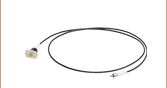
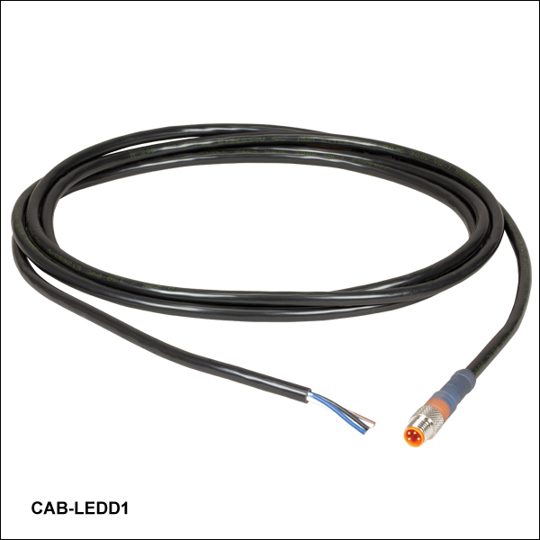
- 一方の端に4ピンのM8コネクタ
- 他方の端に4本の素線
- 長さ2 m、24 AWGワイヤ
4ピンのM8接続ケーブルは、メタルコアPCB上の高出力LEDを、当社のLEDドライバに接続する際に使用できます。接続可能なLEDドライバは、LEDD1B、DC40、DC2200、DC4100およびDC4104(DC4100 とDC4104にはDC4100-HUBが必要)です。
ピン接続
上図では、オス型コネクタと接続可能なLEDコネクタのリストが掲載されています。 このコネクタは、標準品のM8x1丸型センサーコネクタです。 ピン1と2はLEDへの接続用。なお、このページに掲載されている、LED付きPCB基板には、マウント付きLEDとは異なり、EEPROMが付属しない点にご注意ください。したがってピン3とピン4は未接続としてください。 また、こちらに掲載されているピン配列図は、当社製品以外のLEDドライバには適用できない場合もありますのでご注意ください。
お客様がお持ちの電源をお使いいただく場合には、4ピンメス型M8コネクターケーブル(型番CON8ML-4)もご用意しています。